
3
Integration of SAA Capabilities into a UAS Distributed Architecture for Civil Applications
3.1 Introduction
In this chapter the integration of ‘sense and avoid’ (SAA) capabilities into a distributed architecture for unmanned aircraft systems (UAS) is discussed. The presented UAS architecture provides a framework that enables rapid development and integration of hardware and software components required for a wide range of civil missions. This framework includes a number of common services,1 which are envisioned as necessary for most missions – such as flight plan management, mission management and contingency management, among others.
One of the most important issues that needs to be addressed when developing a UAS architecture is SAA. This chapter tackles SAA from two perspectives. Firstly, it discusses integration of SAA capabilities in mission-oriented architecture. In contrast with commercial aviation, where missions mostly consist of flying from an initial location to a given destination, unmanned systems may be used in a wide variety of situations. The UAS response in case of conflict has to be defined in a way that minimizes its impact on the mission being carried out. Secondly, system design and operations considerations aimed at making the UAS behavior more predictable and facilitating conflict prevention are also provided.
The proposed architecture provides a basis for building flexible UAS that can operate in multiple scenarios. It includes a wide set of services (see Section 3.3) to select from according to the needs of each specific mission. These services can be reconfigured so that there is no need to create a new implementation for each scenario. In this way, by combining components that can easily be added, removed and reconfigured, the user can benefit from faster preparation and deployment of the system. Operating on top of commercial off-the-shelf (COTS) components, cost-effectiveness is further improved.
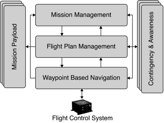
Figure 3.1 shows how the main UAS services are organized. At the bottom of the figure, a COTS flight control system (also known as autopilot) is found. The autopilot provides waypoint-based navigation. Interaction with the autopilot takes place through an intermediary layer that provides a hardware-independent interface. A flight management layer is responsible for performing the flight plan. In the proposed system, an XML-based language is used to specify the flight plan [1]. This language improves on the waypoint-based navigation method used in most commercial autopilots by providing higher-level constructs, with richer semantics, that enable adaptation to mission progress. Some ideas are based on current practices in commercial aviation industry for the specification of area navigation (RNAV) procedures [2]. Alternative flight paths for conflict and emergency situations can also be included in the flight plan. The mission management layer is in charge of orchestrating operation of the different components. The mission management layer interacts with payload-related services and can also adapt the flight plan to the mission needs. All these flight and mission components are complemented by contingency and awareness services. Contingency services continuously evaluate the health of the system and trigger reactions when something goes wrong. Awareness services, which implement the SAA capabilities, provide conflict detection and management related to the environment where the UAS is operating.
Figure 3.1 Organization of main UAS services
Nowadays, there is a strong focus on providing technical solutions to the SAA problem. But for these solutions to be fully effective, they need to be integrated into an architecture that takes into account the UAS flight and mission as a whole.
There are two types of conflict: (a) tactical conflicts, which require immediate reaction and (b) strategic conflicts, where selection of a predefined alternative path is possible. Table 3.1 provides some examples of potential conflicts and the UAS behavior during the reaction. A rapid response to a tactical conflict will be achieved by pre-empting flight and mission layers and directly operating on the UAS throttle and control surfaces. In a strategic conflict, with less stringent constraints on the reaction time, the flight plan can be modified or a predefined alternative flight path can be selected.
Table 3.1 Tactical versus strategic conflict handling
| Tactical | Strategic | |
| Source of conflict | Aircraft collision, terrain avoidance | Weather conditions, ATC constraints, predictable mid-air conflicts |
| Response | Direct commands to UAS control surfaces and throttle | Change flight plan or execute an alternative flight path |
An additional way to prevent conflict situations consists of making the UAS behavior as predictable as possible and making this information known to other airspace actors. The UAS follows predetermined depart and approach patterns and restricts its flight trajectory to the one described in its flight plan, which also contains possible alternatives. Doing so will also make the system more likely to obtain an airworthiness Certificate of Authorization (COA), since regulation authorities will not allow unmanned systems with unpredictable behavior to operate in non-segregated airspace.
The next sections describe the proposed architecture and discuss how flight and mission layers interact with awareness components. Sections 3.2 and 3.3 outline the distributed architecture of the system and describe the UAS service abstraction layer (USAL), which defines the interfaces and responsibilities of the system's components. A more detailed view of the main embarked and on-ground components follows in Section 3.4. After that, in Section 3.5, we describe how the system deals with conflict situations. Some strategies for facilitating conflict prevention are discussed in that section. The chapter concludes with the final remarks provided in the conclusions section.
3.2 System Overview
The main goal of our UAS architecture is to provide a platform that enables rapid and flexible development of UAS systems for a wide range of applications [3--6]. Issues that need to be considered when developing such architecture include air-to-ground and air-to-air communications, payload abstraction for a wide range of sensors and actuators, UAS services interconnection, flight and mission management and, of course, contingency and awareness services to, respectively, monitor the system's health and provide information about the environment the UAS operates in. As will be seen, awareness services include the sensing, processing and reaction components required for implementing the SAA capabilities. Definition and development of the UAS services need to be approached taking into account that legal implications and regulatory aspects for the operation of UAS aren't clear yet. Therefore, the architecture itself needs to be flexible enough to be able to evolve and adapt to regulatory frameworks that may also vary from country to country.
3.2.1 Distributed System Architecture
Access to UAS technology is getting easier and cheaper, but important efforts are still required to leverage all its potential in complex surveillance and remote sensing missions. More so, if the platform has to be able to perform a wide range of missions in a diverse set of environments. Current research mainly focuses on UAS flight control and autopilot optimization. Besides that, specific proposals on UAS platforms selection and payload interaction are found for specific missions [7, 8]. In contrast, our architecture does not focus on a specific mission. This diversity of scenarios demands SAA capabilities be integrated into the architecture. In this section, we describe our general-purpose architecture for executing UAS civil missions that will accommodate such SAA services.
In recent years, there has been a clear trend in various fields to move from centralized and monolithic systems to networked and distributed ones. As complexity increases, it seems a good idea to divide functionality into simpler components that cooperate to achieve the overall task. These components are usually interchangeable and can sometimes be redundant, to improve the fault tolerance of the whole system. In addition, in some fields in which specialized and expensive networks are commonly used, for example manufacturing or avionics, there has been a gradual increase in acceptance of common local area networks, specifically Ethernets. Ethernets have been used extensively since the mid-1980s, and are an affordable and proven solution.
In this context, our vision is of an architecture in which low-cost devices are distributed throughout the system and form networks of smart peripherals or intelligent sensors. That is, the proposed architecture is built as a set of embedded microprocessors, connected by a local area network (LAN), in a distributed and scalable architecture. Over the different distributed elements of the system we deploy software components, which we refer to as ‘services’ that will implement the required functionalities (see Figure 3.2). These services cooperate for the accomplishment of the UAS mission. They rely on a communications middleware [9] for exchanging data and commands. The communication primitives provided by the middleware promote a publish/subscribe model for sending and receiving data, announcing events and executing commands among services.
Figure 3.2 Overview of the UAS distributed system architecture
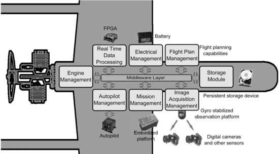
As seen in Figure 3.2, the different services of the UAS are interconnected by a COTS Ethernet network that makes data communication between them very flexible and efficient. Services like the Image Acquisition, Storage Module, Autopilot Management, Real-Time Data Processing and Mission Management are independent and can be executed in different nodes located on the aircraft. The idea behind this is to increment the interoperability, flexibility and extensibility of the system and its individual components. We want to be able to reuse components of the existing system in the implementation of any new system.
In the proposed architecture, several services can be executed on the same node. While this may be seen as a source of runtime and development overhead and excessive in terms of functional decomposition, it is intended to encourage careful design of service interactions and proper separation of concerns. It also provides advantages, such as: independence of the service from deployment and hardware configuration, service interoperability (e.g., different sensors or algorithms for the same functionality), fault tolerance (a service could be replicated in different hardware nodes for redundancy) and service migration (between nodes in case of changes in the system's needs), among others.
To sum up, the proposed architectural approach offers important benefits in our application domain.
- Development simplicity: inspired by Internet applications and protocols, the computational requirements can be organized as services that are offered to all possible clients connected to the network.
- Extreme flexibility: we are free to select the actual type of processor to be used in each node. Different processors can be used according to requirements, and they can be scaled according to computational needs of the application.
- Simple node interconnection: an Ethernet-based architecture provides a much simpler alternative to the complex interconnection schemes needed by end-to-end parallel buses.
- Easier adaptation to changes: the distributed nature of the architecture facilitates integration of new types of sensors and techniques, which is of special importance to adapt to the technical and legal requirements of SAA.
3.3 USAL Concept and Structure
The previous section outlined our distributed architecture and its main benefits. On top of that, a collection of reusable services is provided that will facilitate mission development. We refer to these as the UAS service abstraction layer (USAL).
The USAL is the set of services needed to give support to most types of UAS civil mission. The USAL can be compared to an operating system: computers have hardware devices used for input/output operations. Every device has its own particularities and the operating system offers an abstraction layer to access such devices in a uniform way. Basically, it publishes an Application Program Interface (API) which provides end-users with simplified access to hardware elements. In the same way the USAL considers sensors and, in general, all payload as hardware devices of a computer. It is a software layer that gives facilities to end-users’ programs to access the UAS flight, mission and payload components. The idea is to provide an abstraction layer that allows the mission developer to reuse components and that provides guiding directives on how the services should interchange avionics information with each other. The USAL services cover an important part of the generic functionalities present in many missions. Therefore, to adapt our aircraft for a new mission it will be enough to reconfigure the services deployed in the UAS boards. Even though the USAL is composed of a large set of services, not all of them have to be present in every UAS mission. Only those services required for a given configuration/mission should be deployed in the UAS. As shown in Figure 3.3, USAL services have been classified into four categories: Flight, Mission, Payload and Awareness.
Figure 3.3 USAL services by category
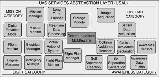
The first element that should be noted in the flight category is the autopilot. Although not exactly a service, it provides the core functionality that enables autonomous flight. The autopilot operation is supervised by the Virtual Autopilot System (VAS), which provides a standardized autopilot-independent interface for other services to interact with. On top of the VAS, the Flight Plan Manager (FPM) offers flight plan specification and management capabilities that go beyond classical waypoint navigation. Contingency-related services help improve the security and reliability of operations. Some of these services are complemented by on-ground counterparts that enable supervision and control by ground personnel. SAA services from the awareness category will interact with services in the flight category to adapt the flight to deal with conflict situations.
The main service in the Mission category is the Mission Manager (MMa). Its role is to orchestrate operation of the overall mission. This service executes a mission specified using a state-machine-like notation. The MMa will be accompanied by other mission-related components, like Storage, Real-Time Data Processing and Communication Management services, among others. If a conflict resolution results in a deviation from the initial flight plan, the MMa needs to be notified so that operation of mission payload can be configured according to the new situation. As an example, some sensors could be switched off while away from the mission area.
The Payload category includes those services that facilitate interaction with embarked devices, especially sensors and actuators. Input devices consist of aircraft state sensors, such as GPS, IMU or anemometers, earth/atmosphere observation sensors, such as visual, infrared and radiometric cameras, not excluding other sensors that may be required for the mission (chemical and temperature sensors, radars, etc.). Output devices are less common, but flares, parachutes or loom shuttles are possible examples of UAS actuators.
The remaining category used to conceptually organize services is awareness. This category deals with those services required to manage interaction of the UAS with its surroundings. Successful integration of UAS into non-segregated airspace requires a number of features to be included in the system architecture, such as interaction with cooperative aircraft and detection and avoidance of non-cooperative aircraft. In these situations the pilot in/on command should stay continuously informed, automatic reactions should also be considered. The awareness category is covered in depth in Section 3.5.
3.4 Flight and Mission Services
In the previous section a general view of the UAS architecture and the USAL concept was provided. In this section we focus on the key services that enable automated mission execution and its supervision. Flight and mission automation services will usually be onboard and, therefore, belong to the air segment. Supervision services UAS operators interact with belong to the ground segment.
3.4.1 Air Segment
The three services that will be covered herein are the Virtual Autopilot System (VAS), the Flight Plan Manager (FPMa) and the Mission Manager (MMa). All three of them have a major role in governing the UAS flight and mission behavior. The VAS and the FPMa, which belong to the flight services category (see Figure 3.4), are the ones with the most relevant role in supporting SAA.
Figure 3.4 Architecture of the USAL flight category
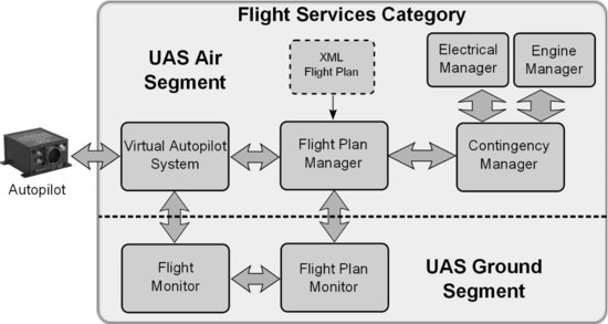
The VAS operates as an interface between the autopilot and USAL services. At one end, the VAS interacts directly with the onboard autopilot and needs to be adapted to the autopilot peculiarities. At the other end, the VAS faces other USAL services providing an interface that hides autopilot implementation details from its actual users. The VAS also offers a number of information flows to be exploited by other USAL services. All the information provided by the VAS is standardized independently of the actual autopilot being used.
The VAS works in conjunction with the FPMa. The FPMa is the USAL service responsible for processing and executing flight plans. In order to execute a flight plan, the FPMa sends navigation commands to the VAS. These commands mainly consist of waypoints which the aircraft has to fly through. Since the flight plan is specified in terms of legs, a certain translation process is needed to convert them into the waypoint sequences expected by the VAS. This flow of waypoint commands is the main form of interaction between the FPMa and the VAS.
Other services belonging to the flight category that also appear in Figure 3.4 are the contingency services, which monitor the health of the electrical and engine sub-systems (more details in [10]). The flight monitor and the flight plan monitor, shown at the bottom of the figure, are part of the ground services and will be covered later.
The functionality implemented by the VAS is divided into four main areas: flight state management, flight telemetry, navigation and status/alarm information.
Flight state management relates to the different operational modes implemented by the VAS. Figure 3.5 displays all possible VAS states. As can be seen, they are organized in different groups according to the flight phase they belong to. The initial state inside each group is shown with an arrow on the top right box state corner. The other arrows show the transitions between different states. The diagram descends from the beginning of the mission to the end, although, in some cases, there are horizontal transitions. When equivalent states are provided by the underlying autopilot, the VAS will act as a proxy that enables access to them. The VAS implements those states not found in the autopilot.
Figure 3.5 VAS state diagram with arrows indicating allowed transitions
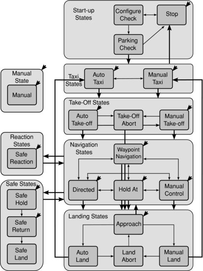
The main VAS states with regard to the SAA capabilities are auto take-off, approach and safe reaction. The first two implement standardized terminal operations that provide predictable behavior and reduce the risk of conflicts. The safe reaction state implements the actual collision avoidance maneuvers.
The other three areas that complete the implementation of the VAS, namely, flight telemetry, navigation and status/alarm information fulfill the following roles. Telemetry refers to the VAS capability to extract telemetry data from the autopilot and provide it to USAL services for exploitation. The navigation information area focuses on VAS input/outputs available during the navigation states. It implements the main navigation commands and provides information regarding the current waypoint and some other flight-related data. Finally, the status/alarm area gives information about current autopilot and VAS status or alarms. Fight telemetry and status/alarm information are outgoing flows, while navigation and state management have an input/output direction.
The inclusion of the VAS greatly improves the flexibility of the USAL framework because:
- The autopilot unit can be replaced by a new version or a different product, and this change will have no impact on the rest of the UAS system. In other words, the VAS implements an abstraction layer that isolates the system from the particular autopilot solution in use.
- An increased level of functionality is provided. Besides providing a set of states that the UAS can take advantage of, the VAS also helps overcome typical limitations of UAS autopilots, such as limitations on the number of waypoints the autopilot can handle.
- In addition, commercial autopilots mainly focus on waypoint navigation, however, the UAS operation may require considering a global perspective, from take-off to the mission and back to landing. The VAS promotes standardized mission-oriented states in order to cope with more elaborate operational requirements.
The FPMa is a service designed to provide flight management functions that go beyond following a predefined sequence of waypoints. The FPMa offers structured flight-plan phases with built-in alternatives, leg-based navigation and constructs to enable forking, repetition and generation of complex trajectories. All these elements are combined in a description of the flight plan that is sent to the FPMa. The FPMa takes this description and dynamically translates it into a sequence of waypoints that are sent to the VAS.
In our system, UAS navigation instructions are represented by means of an XML document that contains a main flight plan plus a number of alternatives. Each one of them is composed of stages, legs and waypoints hierarchically organized as seen in Figure 3.6.
Figure 3.6 Flight plan structure
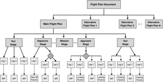
Stages group together legs that seek a common purpose and organize them into different phases that will be performed in a sequence. Legs specify the path that the plane must follow in order to reach a destination waypoint. A waypoint is a geographical position defined in terms of latitude/longitude coordinates that may also be accompanied by target altitude and speed indications.
There are four different kinds of leg: basic, iterative, intersection and parametric. Basic legs specify primitives such as fly directly to a fix, follow a track to a fix, holding patterns, etc. They are based on existing ones in RNAV. Iterative legs are used to indicate that parts of the flight plan should be flown several times. Intersection legs are used in situations where there is more than one possible path to follow and a decision needs to be made. Finally, with parametric legs complex trajectories can be automatically generated from a reduced number of input parameters.
The FPMa is responsible for processing and executing flight plans. It can be seen as a translator of legs to waypoints. This translation process enables leg-based navigation of systems that only support waypoint navigation. The FPMa does not directly interact with the autopilot but with the VAS. From the VAS or autopilot perspective, the FPMa can be seen as a provider of waypoints to fly to. From a mission-related services perspective, the FPMa is the service to talk to in order to control the flight progress and make it adapt to the mission needs. There are multiple possibilities of interaction with the FPMa, the primary ones being setting condition values, sending updates that modify the flight plan and triggering execution of alternative plans.
In the context of SAA, the FPMa enables self-separation in two ways. First, it provides update commands that can be used to add/remove legs or modify existing ones (e.g., changing its altitude). The update commands to perform these changes must be issued by the on-ground pilot on command using the flight plan monitor. If this is not sufficient, during preflight a number of alternative flight plans can be defined, so that the UAS can switch from the main plan to an alternative one in order to avoid a potential conflict. While the system will provide a recommended choice depending on the design of the flight plan during preflight, the final decision will always rely on the on-ground command (pilot).
Alternative flight plans may lead the aircraft to a safe area where a holding pattern can be executed without disturbing other traffic. After that, the mission may be resumed once the mission area is deemed clear. Another possibility consists of having a complete flight plan for executing the rest of the mission to its end. If one wants to resume the main flight plan, the pilot in command will need to specify which leg the mission should continue from. Finally, if we are facing a completely unexpected conflict and feel the mission should be cancelled altogether, these alternative plans can be used to fly to a close airfield.
The last service covered in this section is the MMa, whose role is to extend the UAS automation capabilities by being able to execute a specification of the UAS behavior. The specification determines how operation of embarked services is orchestrated during a mission. The language chosen for describing the UAS behavior is an XML-based representation of state charts [11]. State charts extend traditional state machine diagrams with support for hierarchy and orthogonality, which respectively enable modular descriptions of complex systems and provide constructs for expressing concurrency.
The MMa listens to messages coming from the FPMa, the VAS and other services. These messages translate into events that feed the MMa execution engine. As a result of these incoming events, the MMa may change its current state, generating some kind of response in the process. A response will, usually, consist of a message modifying the behavior of some UAS service; for instance, a message switching on or off some payload according to the current mission phase. In this way, UAS services operate according to the current mission state in a coordinated manner.
The MMa does not directly involve in the response to a conflict situation. However, the choice of an alternative flight plan to perform the mission may require the embarked payload to be configured and operated in a different way. It is the responsibility of the MMa to perform these changes.
3.4.2 Ground Segment
Our vision is to provide a highly capable system and tools to support development of complex UAS-based missions. Automation capabilities are built into the UAS to reduce operators’ workload and cope with situations that require immediate response and cannot wait for external input. Despite its automation capabilities, the system will rely on on-ground personnel to supervise and control the evolution of the mission.
Figure 3.8 displays the main positions at the ground control station. The Flight Monitor (FM) is the system used by the pilot in command to control the UAS flight. To do so, it communicates with the embarked VAS. The Flight Plan Monitor (FPMo) is used to monitor and modify the flight plan. It complements the functionality provided by the onboard FPMa. Finally, the Mission Monitor (MMo) is used to supervise and manage the mission and payload operation.
Figure 3.7 Main on-ground positions
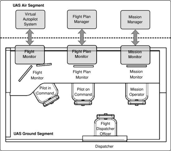
Figure 3.8 Flight Monitor primary screen
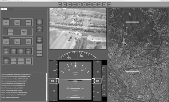
Generally speaking, current UAS autopilots offer manual and/or assisted piloting plus basic waypoint navigation capabilities. Although manual piloting is not the main form of expected interaction, the HMI interfaces are designed to maintain this capability (this is discussed further in the next chapter of the book). The FM is the on-ground service that interacts with the VAS and enables real-time supervision and control of the UAS flight. Using this front-end service, the pilot in command can change the VAS state directly on a displayed diagram. It also displays telemetry emitted by the VAS. The FM offers two separate screens; one of them, focusing on manual piloting, which is always available, and a multifunction screen to exploit higher-level VAS capabilities. With the multifunction screen, the pilot can switch between different views to display information such as VAS states, configuration parameters, telemetry, etc. Figure 3.8 shows the FM primary screen; in this example the FM has been configured to illustrate the VAS states, but in that location of the screen, the pilot can show the VAS states, electrical information or engine information.
The FPMo provides flight plan visualization and tracking capabilities and also permits modification of the flight plan and submission of changes to the FPMa. The FPMo is the ground service responsible for the onboard FPMa. The capabilities required by the FPMo are related to inherent dynamic behaviors offered by the FPMa.
Similarly to the FM human–machine interface, the FPMo interface is divided into two separate screens that work in coordination. The primary screen displays the flight plan and additional annotations in a graphical way. The secondary screen provides different views according to the different operational modes. The different views available in the primary screen are ‘flight plan tracking’, ‘departure tracking’, ‘approach tracking’ and ‘flight plan validation’. These views are complemented by sub-views in the secondary screen that provide additional information, enabling modification of leg properties and configuration of FPMo parameters. More details about FPMo can be found in [12].
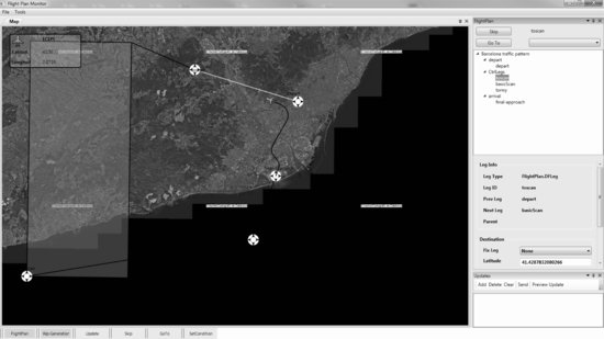
Figure 3.9 shows an overview of the FPMo; the left of the picture illustrates the main screen where the flight plan is monitored. The gray box shows the mission area where the UAS is going to develop a scan pattern (remote sensing mission). The right part of the figure exposes the secondary screen where the different legs of the flight plan can be updated, skipped or replaced.
Figure 3.9 Flight Plan Monitor
The MMo is used to supervise the progress of the mission as defined in the MMa and display mission-related information in a friendly way. For example, during a wildfire monitoring mission, it may present the current state of the fire front on a map. The information produced by the UAS payload, such as sensors or cameras, will be shown in this workstation. The MMo should be highly configurable to fit the specific requirements of each mission.
3.5 Awareness Category at USAL Architecture
UAS are highly instrumented and, thus, the most suitable flight rules for them are IFR.2 However, for civil applications, one of the advantages of UAS is precisely its capability to fly at low altitude, where VFR3 aircraft are found. Therefore, the UAS has to be integrated into non-segregated airspace. A critical enabler for UAS integration into non-segregated airspace are the SAA systems, which have to ensure an equivalent capability to ‘see & avoid’ in manned aviation (performed by flight crew, usually with the support of onboard tools and systems like TCAS). A possible definition of the SAA system is the onboard, self-contained ability to:
- detect traffic, terrain, weather and obstructions that may lead to a conflict;
- determine the right of way of traffic; and
- maneuver according to the rules.
The USAL awareness category is responsible for being ‘aware’ of what is happening outside the UAS in order to manage suitable responses to any awareness conflict. Following these SAA intention statements, the awareness category translates these abilities to USAL services. In that way, as in the SAA case, the main functionalities of this category are:
- Self-separation (SS). SAA system function where the UAS maneuvers within a sufficient timeframe to prevent activation of collision avoidance maneuver while conforming to accepted air traffic separation standards.
- Collision avoidance (CA). SAA system function where the UAS takes appropriate action to prevent an intruder from penetrating the collision volume.4
These main functionalities are often represented by a four-layer model showing the separation layers from the UAS perspective: collision avoidance, self-separation, air traffic management and procedural [13, 14]. That is, air traffic management and procedural are two layers which complement the main SAA functionalities.
In this section, we are going to describe how the USAL architecture addresses the SAA concept during the different UAS mission phases. The SAA concept includes a good flight plan design and its communications under a procedural point of view. In that way, a cooperative aircraft5 will know our flight path and can predict the UAS behavior.
To sum up, the SAA concept goes beyond SS and CA, making standardized and predictable procedures a complementary safety layer. For these reasons, this section has been divided into three main parts. The first sub-section outlines preflight procedures in order to design suitable flight plans and corresponding alternative flight plans. After that, predictable depart and approach procedures are described in order to facilitate conflict prevention on the airfield. Finally, SS and CA are discussed during en-route and mission operations.
3.5.1 Preflight Operational Procedures: Flight Dispatcher
In civil aviation, a set of procedures and standardized practices are followed in order to operate safely, efficiently and regularly all kind of aircraft. Criteria of safe operating practice are found in ICAO Annex 6, Part I [15] for commercial air transport operators, while Parts II and III of the same Annex deal with general aviation and helicopter operations respectively. In these standards and recommended practices one can find, for instance, what kind of documentation an operator should provide to flight crews, what are the responsibilities and duties of the pilot in/on command before, during and after a flight, etc.
The flight operations officer, also known as the flight dispatcher, is one of the key actors during aircraft operations, sharing duties and responsibilities with the pilots in/on command. Flight dispatchers assist pilots in/on command with all tasks related to flight preparation (for example, aircraft load planning, meteorological briefing, operational, air traffic services flight planning, etc.). We propose a new dispatching methodology focused on UAS civil applications; assisting UAS operations following the same philosophy of flight dispatching practices used in civil aviation. However, due to the singularities of the UAS systems, flight dispatching is merged with pilot in/on command duties as well as mission analysis and operation, i.e., the mission and flight plan dispatching. The overall process is mission-centric, focusing on all the requirements needed to properly implement the assigned tasks, but also integrating the traditional dispatching requirements. The full process is described in [16], however, we are going to summarize the whole process in order to understand why the dispatcher is important to SAA concepts.
The proposed dispatching process is built upon the USAL architecture and is introduced to characterize:
- The UAS mission and flight plan: its objectives, payload requirements, operation, flight plan, flight plan alternatives, etc.
- The UAS airframe: its various characteristics, performance, USAL services required for managing the flight and the mission, available payload bays, fuel and electrical architecture.
- Required sensors and other payload, etc.
All these elements are combined together in an iterative dispatching flow as shown in Figure 3.10. Starting from the mission objectives, a UAS has to be selected that initially fits the mission requirements. After that, the overall set of services required to implement the mission, and all types of payload (communication, computation, sensors, batteries, etc.), have to be selected. Then, the payload has to be organized in the airframe, services assigned to computation payload modules, and the initial flight plan template instantiated into an operative one.
Figure 3.10 Organization of the UAS mission dispatching process

The result of the process is the actual UAS configuration in terms of fuel, electrical system, payload configuration, flight plan, etc.; but also the operational flight plan, alternative routes and landing sites in case of deroutings and/or emergencies. In addition the detailed USAL service architecture is configured, how services are assigned to payload modules, and even the set of rules and system reactions that define the contingency planning.
In order to integrate the UAS into non-segregated airspace, it's critical to know the UAS flight plan intentions. Not only in terms of the mission flight plan but also in terms of flight reactions during the mission. In a realistic environment, the UAS cannot decide on its own the proper reaction in a given SAA conflict. Therefore, it is really important at the dispatcher phase to define the different flight plans, alternative routes and landing sites in case of deroutings and/or emergencies. To sum up, we believe that the dispatch phase has to be included as part of a UAS mission. That is, instead of starting the UAS mission at taxi or depart operations, it will start at the dispatcher process.
Going back to Figure 3.10, only the Flight Plan & Mission Detail phase of the dispatch process is related to SAA, specifically with the term ‘Avoid’. With the help of a Geographic Information System (GIS), the pilot in/on command and the flight dispatcher officer will design the flight plan and the flight plan alternatives taking into account flight rules, weather changes, cities, terrain, etc.
The result of this part of the dispatch process is the Flight Plan Document structured in different levels as described in Section 3.4.1, where the mission flight path and all its flight path alternatives can be found. In that way, this file can be distributed or transmitted by the data link in order to disclose our flight intentions. Thus, cooperative aircraft can know our flight path and predict SAA reactions.
3.5.2 USAL SAA on Airfield Operations
The depart operations are extensible to approach and landing operations; both cases involve operating UAS in airports. Regarding SAA, the authors believe that the use of standardized and predictable depart/approach procedures for UAS would be a complementary safety layer, potentially decreasing the complexity of SAA systems. Inspired by some existing procedures for (manned) general aviation, some automatic and predefined procedures for UAS are proposed. In this sub-section, we are going to summarize the main aspects of the airfield operations; a full version of this work is detailed in [17, 18].
The safe, efficient and regular operation of all kinds of aircraft relies mainly on a set of procedures and standardized practices. Aircraft operations can be divided into two main groups: those aircraft evolving under VFR and those which are under IFR. For example, pilots evolving under VFR rely entirely on what they see outside the cockpit for the control of the aircraft and its navigation. Conversely, pilots flying under IFR use several onboard instruments to control and navigate their aircraft and in almost all classes of airspace, the separation from other aircraft is ensured by an air traffic control (ATC) service.
From an end-user point of view, the operation of a UAS is similar to the operation of a manned aircraft in IFR conditions. In general, the UAS operators will not use external visual references in order to control the aircraft and navigate since it is expected that UAS will be equipped with autopilots and flight planning capabilities. However, even if a UAS is fully capable of flying under IFR rules, an extra functionality is needed if the UAS operations performed are in an airport with no IFR procedures published. In fact, it is quite probable that initial UAS operations in civil airspace will be conducted in small airports instead of busy ones. Hence, it is also quite probable that in such airports no IFR operations will be published. Moreover, in these airports the majority of surrounding traffic will be general aviation, with aircraft that are not as well equipped as commercial ones. Therefore, in order to minimize the risk of mid-air collisions, it is necessary to add an extra safety layer by introducing procedures that are predictable and well known by all users [19]. We propose the integration of UAS for the departure, arrival and approach phases and in particular, for VFR environments under the USAL architecture. Thus, some specific UAS procedures are proposed for these environments in order to operate safely while at the same time minimizing the interference with other traffic.
As commented before, VFR operations are based on visual cues that the pilot takes from the cockpit. For unmanned flight, one may think that a possible solution for VFR operations would be to install a set of cameras in the aircraft and transmit all the video signals to the ground control station, where the UAS pilot would remotely fly the aircraft in visual conditions. Even more elaborate ‘sense’ techniques have already been proposed by other researchers (see, for instance, [20--24]), but some of these approaches would not be a feasible solution for many UAS implementations (especially for those using medium to small platforms). Moreover, besides the potential ‘sense’ system(s) used for a specific UAS, the use of standardized and predictable procedures for the UAS would be a complementary safety layer, which would potentially decrease the complexity of these SAA systems.
These complementary procedures are conceived, aiming to minimize the interference with surrounding traffic and also the pilot in/on command work load, which will be connected with the UAS by using some kind of data-link communications. As mentioned earlier, the mid-air collision risk due to the use of UAS is reduced if procedures are clearly defined. This means that a UAS equipped with one (or more) SAA systems, which is also executing some kind of standardized procedures, will have more chance of being certified. The use of these standardized procedures becomes even more important when the aircraft evolves close to an airport with VFR traffic, because this is where the major risk for mid-air collision exists [25]. In addition, the procedures may facilitate the coordination with eventual ATC or, in the non-controlled case, with the rest of the pilots operating in the same area.
In this sub-section, we have considered that the UA has similar performance to other aircraft flying at the same airport. It is clear that for UAS with different performances (such as mini/micro UAS) than other aircraft, separate airfield traffic patterns may be considered (such as is done nowadays in airfields with small ULM or gliders). On the other hand, the operations described here are oriented more toward tactical and large UAS.
Depart Operations
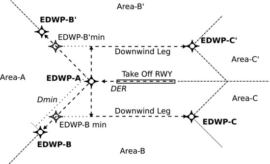
It is clear that a manual take-off is always possible, especially if the pilot in/on command is present in the departing airfield and has visual contact with the aircraft. In this case, the UAS would fly up to a point and/or height where the navigation phase can be initiated and the autopilot system engaged. Yet, the authors propose an automatic depart phase to execute this process more easily, more predictably and therefore, in a safer way. Thus, the take-off phase will automatically fly the aircraft from the departing runway to an end of departure waypoint (EDWP). These waypoints are located close enough to the airport in order to avoid complex navigation paths, but far enough to reduce as much as possible conflicts with surrounding traffic. Once at the EDWP, the UAS will start the navigation phase (see Figure 3.11).
Figure 3.11 EDWP and associated departure areas
These maneuvers are implemented at the USAL architecture by services such as the VAS and the FPMa. The VAS must load at the dispatcher phase all the information related to the departure (such as runways, EDWP, altitude to navigation state) before the flight. When the UAS is calibrated and ready to fly, the pilot in command will ask to change to ‘taxi’ state (as described in Section 3.4.1). In this state the UAS will have to address the runway, by means of the taxi procedure suitable for each airport in order to not disturb other aircraft.
When the pilot in command switches to ‘auto take-off’, the VAS will have to perform this technique with the control of the autopilot supervised by the pilot in/on command. When the UAS reaches the safe navigation altitude at the EDWP, it will automatically change its state. If there is a flight plan charged on the VAS queues, the UAS will start the navigation of those waypoints. If not, it will perform a waiting maneuver at a ‘save hold’ state until new waypoints are uploaded.
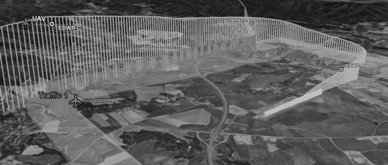
In order to test the departure maneuver proposed, and the good working of the USAL services that implement the action, a simulation platform has been implemented [26]. Figure 3.12 shows the simulation of a UAS in departure mode with its EDWP powered by the Google Earth® API. As can be seen, the departure procedure does not obstruct air traffic that flies at a lower altitude level.
Figure 3.12 Departure procedure tested at the simulation platform
Approach Operations
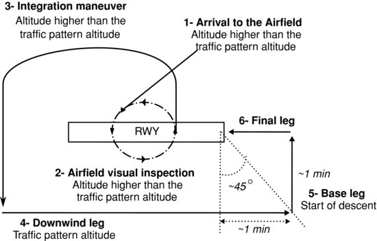
Following the same philosophy as with the departures, we propose some standardized procedures that may be performed by the UAS in the approach phases to a given airport. These procedures are inspired by what is flown currently by manned aircraft operating in VFR and in non-controlled airfields (see Figure 3.13). We think that these procedures will allow us to improve the predictability of UAS trajectories, so they might also be used in case of flying to an airport even with ATC services, but with no IFR procedures published.
Figure 3.13 Standardized procedure for the arrival and approach operations in non-controlled VFR airfields
As with the depart operations, for the development of the arrival procedures the VAS and the FPMa implement the maneuvers. There is also a preflight configuration needed at the dispatching state. The VAS must know the land pattern used at each runway selected.
The FPMa or the pilot in command will command the VAS to start approaching the runway in order to begin the landing pattern. When the UAS arrives at the airfield, it starts a hold pattern over the airfield higher than the traffic pattern. This technique is used as a waiting procedure while there is a visual inspection of the field. When the UAS is able to begin the landing it starts the integration maneuver by incorporating into the traffic at the down wing leg. These legs are defined by waypoints charged by the FPMa and commanded by the VAS. The base leg is for reducing altitude and entering the final leg with the UAS ready to land.
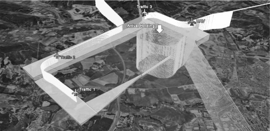
This proposal has been tested in the simulation scenario. Figure 3.14 shows the procedure described in this sub-section, where the UAS holds over the airfield. Traffic 1, 2 and 3 simulates the landing maneuvers effected by other aircraft. The UAS has to wait until aircraft 3 starts its landing procedure for the UAS to integrate into the arrival traffic.
Figure 3.14 Arrival procedure tested in the simulation scenario
3.5.3 Awareness Category during UAS Mission
Flight services are in charge of aircraft management and UAS airworthiness under nominal conditions. However, the awareness services are able to administer UAS control in a critical awareness situation since air traffic, or civilian lives, may be in danger. In this case, mission and payload services take second place until the flight conditions return to normal.
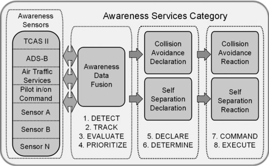
The awareness services category is a system capable of detecting problems, finding solutions and reacting to them. The complexity of this system lies in translating to programs and sensors the ability of a pilot to sense and react to fast avoiding obstacles. There are some actions that a human brain carries out in milliseconds that must be translated to a UAS. These SAA actions have been categorized by the FAA [13] into eight sub-functions: detect, track, evaluate, prioritize, declare, determine action, command and execute.
To implement the eight sub-functions, the awareness services are divided into different services that implement several responsibilities and interact with each other. Figure 3.15 introduces these services and their interactions. The category is defined by:
Figure 3.15 Composition of awareness service category
- awareness sensors
- awareness data fusion
- self-separation declaration/collision avoidance declaration
- self-separation reaction/collision avoidance reaction.
The arrows in the picture indicate the system flow. Arrows that have two directions indicate that the following sub-system can ask on demand the data available. The awareness sensors gather all the data from the environment through the sensors onboard, and/or the air collision avoidance systems. The sensor information is collected and preprocessed to be sent to the awareness data fusion service. This service links the awareness information with specific data, from the rest of the USAL services, such as flying state, current mission tasks, flight telemetry, etc. After evaluating the situation, the awareness data fusion transfers responsibility to the collision avoidance declaration or self-separation declaration. These modules declare the current situation of the risk, and after determining which action to follow, they call their reaction service to command and execute its decision. Next, we are going to explain in detail each part of the category.
Awareness Sensors
This module is the sensors/system input of the awareness category. The goal here is to feed the UAS with at least the same amount of information a pilot on board has. There are several sensor types and technologies which can be used in the ‘sense’ sub-system of a SAA, for example: radar sensors, electro-optical sensors, laser sensors, infrared sensors, cooperative systems or a combination of these.
The sense scenario can be sub-divided into passive or active techniques applicable in cooperative or non-cooperative traffic environments. On the one hand, the active cooperative scenario involves an interrogator monitoring a sector ahead of the UAS to detect oncoming traffic by interrogating the transponder on the other aircraft. The active non-cooperative scenario relies on a radar sensor scanning a sector ahead of the UAS to detect all traffic, whether transponder-equipped or not. On the other hand, the passive cooperative scenario relies on everyone having a transponder, but with everyone's transponder broadcasting its position, altitude and velocity data. The passive non-cooperative scenario is the most demanding one. It is also the most analogous to the human eye. A system in this scenario relies on a sensor to detect and provide azimuth and elevation to the oncoming traffic.
However, all these sensors have not yet shown enough maturity to be considered for every UAS size. For instance, a radar sensor or TCAS II or ADS-B systems would not be suitable for mini UAS. Therefore, as each UA may present a different sensor configuration, we are abstracted of a particular sensor solution for a specific UA.
The first two awareness sensors illustrated in Figure 3.15 are the Traffic Alert and Collision Avoidance System (TCAS II) and Automatic Dependent Surveillance – Broadcast (ADS-B) systems. The TCAS II and ADS-B systems monitor the airspace around an aircraft, independent of air traffic control, and warn the UAS of the presence of other aircraft which may present a threat of mid-air collision. For example, TCAS II can also generate collision warnings in the form of a ‘traffic advisory’ (TA) and also offers the pilot direct instructions to avoid danger, known as a ‘resolution advisory’ (RA). Small UAS are difficult to see visually and sense electronically (e.g., radar), therefore, the use of electronic broadcast of the aircraft's state vector data might be a potential sense option. However, small UAS have limited power, weight and space to put onboard existing ADS-B units. Nevertheless, some research efforts have been made in this line in order to solve that limitation. For instance, the MITRE Corporation began (in 2006) the use of lightweight and low-power versions of ADS-B for small UAS [27].
Depending on the airspace type (controlled airspace), SAA functionalities are going to be developed by the ATC. In these cases the UAS has to be capable of communicating and following the ATC commands, which are in charge of ensuring ‘well clear’ maneuvers. In addition, the UAS should be able to broadcast current flight status and future intent following the standardized operation procedures. The MITRE Corporation is developing an autonomous situation awareness and information delivery system to allow timely communication from UAS to ATC, nearby pilots and other operational personnel during a lost-link situation [28].
In nominal conditions and with all communication links working correctly, the pilot in/on command can develop ‘sense’ functions (by means of onboard cameras) and broadcast the UAS current flight status. However, relying on a pilot in/on command, the UAS incurs human latency, adding the latency of the data link bringing the image to the ground for a decision and the avoidance command back to the UAS. This added latency can range from less than a second for line of sight (LOS) links to more time for satellite links. Latency and the possibility of a lost-link situation are sufficiently important inconveniences to develop an awareness situation with the pilot in/on command.
Sensor A, Sensor B and Sensor N illustrate the possibility of using sensors such as radars or cameras for the ‘sense’ part. For example, radar uses electromagnetic waves to identify the range, altitude, direction or speed of both moving and fixed objects. It is a very mature technology, ‘all-weather’ and provides accurate range, direction and closing speed. Unfortunately, the size and weight of microwave radar sensors are substantial; thus, use in aviation (especially in smaller UAS) is limited. Some research efforts have been made in this field in order to integrate radars in a UAS. In 2003, NASA equipped a UA with a radar system able to detect non-cooperative targets and a traffic advisory system to detect cooperative ones. With this UA configuration and traffic surrounding the aircraft, NASA made some successful flight tests [29, 30]. Kemkemian [31, 32] presents low-cost multiple-input multiple-output (MIMO) radar for UA airframes which allows the location of the radar without any moving parts.
The optical sensors (visual sensors) use the natural waves coming from the intruding aircraft to detect it. Software programs analyze incoming streams of pixilated digital horizon for aberrations in the flow of the pixels, which generally mark an intruding object. Important research efforts have been addressed to the development of detection algorithms, e.g. [24,33]. This technology is also mature and relatively low cost, however, atmospheric disturbances can interfere and hinder its ability to detect oncoming traffic. In addition, to achieve the required field of view, sensors have to be located in different positions of the aircraft. Karhoff [34] developed an interesting assessment of SAA technology for the army's ‘Warrior’ UAV, declaring that visual technology offers the best chance for FAA approval, waiting on further maturity and improvements in other technologies. In addition, the study discusses other potential sense technologies such as laser radar, infrared sensors and bistatic radar.
As has been mentioned in the previous paragraphs, there are various sensor technologies which can be used in the ‘sense’ sub-system of SAA. Each technology presents positive and negative attributes to be integrated in UAS. The suitable technology to be onboarded will depend on the UAS size and the airspace class where the UA is going to fly.
Going back to Figure 3.15 and from an architecture point of view, we are going to be abstracted of the awareness sensor implementation details. One service is provided for each sensor which operates as a sensor driver. Each of these drivers is in charge of interacting with a specific awareness sensor. This service operates similarly to the way that drivers work in operating systems, removing the implementation details from actual sensor users. These awareness sensor drivers are where the first preprocess data algorithms (such as detection algorithms) will be located. In that way, just relevant data will feed the awareness data fusion service.
Awareness Data Fusion
Once the sense of the awareness category is satisfied by means of the awareness sensor services, the UAS must collect all this information and use it efficiently. The detection information provided by several awareness sensors should be evaluated and prioritized taking into account the rest of the UAS information such as telemetry, flight plan and mission information.
The goal of the awareness data fusion (ADF) is to implement the first four of the eight sub-functions: detect, track, evaluate and prioritize. With the detect function, we have to determine the presence of aircraft or other potential hazards, while track is to keep this information during time and estimate the future position of the intruder.
The ADF collects current air traffic, meteorological and terrain state (digital elevation model, DEM) of the aircraft as seen by the different sensors of the aircraft. The ADF fuses and centralizes all data received to offer an awareness overview. All of this data is put side by side with the information given by other USAL services: UAS flight telemetry provided by the VAS (current position and bearing), flight plan mission information provided by the FPMa (whole mission flight plan and its alternatives), AGL altitude from DEM, etc.
Figure 3.16 Awareness data fusion service interaction
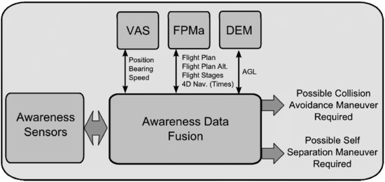
Figure 3.16 illustrates the main ADF interaction inside the USAL architecture. The VAS provides flight telemetry for the rest of the services. This data is important to compare the UAS current position, bearing and UAS speed with other airspace users. The FPMa offers a flight path and alternatives to compute future conflicts and ensure self-separation during the mission. In the future, this service has to incorporate 4D navigation in order to know at what moment the UAS is going to arrive at the different flight plan waypoints. The FPMa stages the UAS goes through to perform a mission are also provided (such as on-ground, departure, en-route, mission or arrival). This data is going to be important in selecting a suitable conflict reaction. The reaction can be different depending on the mission stage.
After grouping the data and validating the state of the mission, the position in the air and all the factors that a pilot onboard would compare, it must evaluate the collision risk based on these predictions and the current data of the UAS, and prioritize the reaction – e.g., TCAS-II RA messages or ATC indications. As a result of this prioritization, the ADF service may choose between two possible outputs: collision avoidance maneuver required or self-separation maneuver required. In other words, the system has detected a hazardous situation which requires treatment.
Self-separation and Collision Avoidance Declaration
SAA is the capability of a UAS to remain ‘well clear’ and avoid collision with other airborne traffic. The two functions of SAA are self-separation and collision avoidance. In the USAL architecture we have divided these functions into two different steps: the collision/self-separation declaration and collision/self-separation reaction. In order to explain the system, we have to understand the different volumes of risk.
Figure 3.17 UAS ATC separation, self-separation and collision avoidance [13]
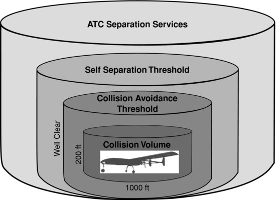
Figure 3.17 explains the different dangerous zones and the condition of awareness. As can be seen, the ATC separation service volume is where there is no threat, but an aircraft detected far away can be turned into an obstacle. In controlled airspace, ATC ensures a safe distance is maintained from other aircraft, terrain, obstacles and certain airspace not designated for routine air travel. The ATC is in charge of giving the order to reconfigure the path and avoid crossing trajectories. The second volume is called the self-separation threshold. In this situation, the ATC may have failed, or another unresolved alarm may have occurred, and the aircraft detected turns out to be a threat. The SS could be the only function provided given that the safety analysis demonstrates that the target level of safety (TLS) can be met with SS alone [13]. However, when all forms of SS have failed, we are now at the third volume and the CA takes appropriate action to prevent a threat aircraft from penetrating the collision volume. On rare occasions the UAS SS functions may conflict with ATC separation services, and as a general rule the UAS will follow ATC separation services.
Back to Figure 3.15, where the awareness USAL services are defined. It can be seen that the SS and CA are divided into four different services:
- Services to manage the declaration (collision avoidance declaration, CAD and self-separation declaration, SSD).
- Services to command and execute the reaction (collision avoidance reaction, CAR and self-separation reaction, SSR).
Once the ADF resolves between CA and SS, the declaration services must declare if any action is required to keep the intruder from penetrating the collision volume. If the declaration services announce that an action is required, they have to determine and propose what sort of response is required to maintain the ‘well clear’. This determination says whether a SS or CA reaction is needed. In the SS case, where the UAS has enough time to react, the action required to maintain the ‘well clear’ has to be supervised by the pilot on command and previously defined in most cases. An aspect that should be considered during this process is establishing who has the right of way. At the moment, the UAS regulation material is not clear on which category to place the UAS in and therefore know its right of way.
Self-separation and Collision Avoidance Reaction
After the declaration services have determined the risk, the reaction services will take the lead and implement the command and execute functions. The reaction services must command the action to the UAS, and the UAS has to execute the commanded action. In order to do so, we propose using FPMa alternatives. During the aircraft dispatcher phase, the dispatcher officer and pilots in/on command have designed the flight plan mission and flight plan alternatives in order to give response for any UAS contingency.
As has been explained in controlled airspace, the first cylinder is managed by the ATC separation services. In this case, the ATC separation service commands have to be followed, updating the flight plan through the FPMa updates. These changes in the flight path have to be supervised by the pilot on command who has the ability to immediately affect the trajectory of a UA if necessary.
When the UAS is flying in non-controlled airspace, once the UAS self-separation threshold has been breached, the UAS has to react to ensure ‘well clear’ of the threat. In this case, the SSR service receives the required action to solve the conflict. If any CAR is required, the reaction is executed by the VAS by means of safe reaction state, for instance making an immediate change of bearing. A change in this state means stopping the current VAS operation to react as soon as possible. In safe reaction state, the VAS accepts several parameters to react to conflicts. It needs the heading to avoid the obstacle and the operation priority. Through the priority parameter the VAS knows how severe the maneuvers have to be. These changes of the heading have to develop following ICAO Annex 2 ‘Rule of the air’.
3.6 Conclusions
In this chapter, integration of SAA capabilities into a distributed architecture for UAS civil applications has been presented. The USAL architecture takes into account the UAS flight, mission, payload and awareness as a whole. Special attention has been paid to the composition of the awareness category where ‘pure’ SAA functions, such as self-separation and collision avoidance, are developed. Particular techniques for SS or CA are important for the UAS civil integration; however, these techniques have to be integrated inside the UAS architecture. SS and CA systems have to cooperate with the UAS autopilot and flight plan manager to ensure safe flight. This chapter describes the awareness services definition, responsibilities and interactions with other services of the USAL architecture.
Another important issue tackled is prevention operations in order to anticipate and avoid SAA conflicts. Suitable flight plan designs during the dispatch process should prevent future conflicts. On the other hand, the use of standardized and predictable maneuvers for the UAS, such as depart and approach procedures, should be a complementary safety layer for avoiding hazardous traffic situations. Preflight process and predictable airfield operations are examples of that statement.
Acknowledgments
This work has been partially funded by the Ministry of Science and Education of Spain under contract CICYT TIN 2010-18989. This work has been also co-financed by the European Organization for the Safety of Air Navigation (EUROCONTROL) under its CARE INO III programme. The content of the work does not necessarily reflect the official position of EUROCONTROL on the matter.
References
1. Santamaria, E., Royo, P., Barrado, C., Pastor, E., and Lopez, J., ‘Mission aware flight planning for unmanned aerial systems’, in Proceedings AIAA Guidance, Navigation and Control Conference (GN&C), Honolulu, HI, August 18–21, 2008, pp 1–21.
2. EUROCONTROL, ‘Guidance material for the design of terminal procedures for area navigation’, 2003.
3. SC-203 RTCA, ‘Guidance material and considerations for unmanned aircraft systems’, Radio Technical Commission for Aeronautics, Document Do-304, Washington, DC, March 2007.
4. RTCA, ‘Operational services and environmental definition (OSED) for unmanned aircraft systems (UAS)’, Radio Technical Commission for Aeronautics, Document Do-320, Washington, DC, June 2010.
5. Cox, T., Somers, I., and Fratello, D., ‘Earth observations and the role of UAVs: a capabilities assessment’, Technical Report, NASA 20070022505, August 2006.
6. UAVNET, ‘European civil unmanned air vehicle roadmap, action plan and overview’, Technical Report, 2005.
7. Iscold, P., Pereira, S., and Torres, A., ‘Development of a hand-launched small UAV for ground reconnaissance’, IEEE Transactions on Aerospace and Electronic Systems, pp 335–348, January 2010.
8. NASA Ames Research Center, SIERRA project 2009, Earth Science Division (WRAP): http://www.espo.nasa.gov/casie/.
9. Lopez, J., Royo, P., Pastor, E., Barrado, C., and Santamaria, E., ‘A middleware architecture for unmanned aircraft avionics’, in ACM/IFIP/USENIX International Conference on Middleware Companion, New Port Beach, CA, November 2007, pp 1–6.
10. Pastor, E., Royo, P., Santamaria, E., Prats, X., and Barrad, C., ‘In-flight contingency management for unmanned aerial vehicles’, in AIAA Unmanned … Unlimited Conference, Seattle, WA, April 6–9, 2009, pp 1–15.
11. Harel, D. and Politi, M., Modeling Reactive Systems with Statecharts: The STATEMATE Approach, McGraw-Hill, New York, 1998.
12. Pastor, E., Santamaria, E., Royo, P., López, J. and Barrado, C., ‘On the design of a UAV flight plan monitoring and edition system’, in Proceedings of the IEEE Aerospace Conference, AIAA/IEEE, Big Sky, MT, March 2010, pp 1–20.
13. FAA, ‘Sense and avoid (SAA) for unmanned aircraft systems (UAS)’, Sense and Avoid Workshop, Federal Aviation Administration, October 2009.
14. Chen, D.W.-Z., ‘Sense and avoid (SAA) technologies for unmanned aircraft (UA)’, National Cheng Kung University (NCKU), December 2008, http://ord.ncku.edu.tw/ezfiles/3/1003/img/467/20081204_ppt.pdf.
15. ICAO, I.C. International Standards and Recommended Practices, Operation of Aircraft, Annex 6 to the Convention on International Civil Aviation, 1998.
16. Prats, X., Pastor, E., Royo, P., and Lopez, J., ‘Flight dispatching for unmanned aerial vehicles’, in Proceedings of AIAA Guidance, Navigation and Control Conference and Exhibit (GN&C), Honolulu, HI, August 2008, pp 1–21.
17. Delgado, L., Prats, X., Ferraz, C., Royo, P., and Pastor, E., ‘An assessment for UAS depart and approach operations’, 9th AIAA Aviation Technology, Integration, and Operations Conference (ATIO), Hilton Head, SC, September 21–23, 2009, pp 1–16.
18. Prats, X., Delgado, L., Royo, P., Pérez-Batlle, M., and Pastor, E., ‘Depart and approach procedures for UAS in a VFR environment’, AIAA Journal of Aircraft, in press, 2011.
19. Weibel, R.E. and Hansman, J., ‘Safety considerations for operation of different classes of UASs in the NAS’, 4th AIAA Aviation Technology, Integration, and Operations Conference (ATIO), Chicago, 2004, pp 1–11.
20. Fasano, G., Accardo, D., and Moccia, A., ‘Multi-sensor-based fully autonomous non-cooperative collision avoidance system for unmanned air vehicles’, Journal of Aerospace Computing, Information, and Communication, 5(10), 338–360, 2008.
21. Korn, B. and Edinger, C., ‘UAS in civil airspace: demonstrating “sense and avoid” capabilities in flight trials’, 27th Digital Avionics Systems Conference, Orlando, FL, October 2008, pp 4.D.1-1–4.D.1-7.
22. Kephart, R.J. and Braasch, M.S., ‘See-and-avoid comparison of performance in manned and remotely piloted aircraft’, IEEE Aerospace and Electronic Systems Magazine, 25(5), 36–42, 2010.
23. Tadema, J. and Theunissen, E., ‘A concept for UAS operator involvement in airborne conflict detection and resolution’, IEEE/AIAA 27th Digital Avionics Systems Conference, St. Paul, MN, October 2008, pp 4.C.1-1–4.C.1-12.
24. Carnie, R., Walker, R., and Corke, P., ‘Image processing algorithms for UAV sense and avoid’, in Proceedings of IEEE International Conference on Robotics and Automation (ICRA 2006), Orlando, FL, June 2006, pp 2848–2853.
25. Simon, J.N. and Braasch, M.S., ‘Deriving sensible requirements for UAS sense-and-avoid systems’, 28th Digital Avionics Systems Conference (DASC), Orlando, January 2008, pp 6.C.4-1–6.C.4-12.
26. Royo, P., Lopez, J., Tristancho, J., Lema, J.M., Lopez, B., and Pastor, E., ‘Service oriented fast prototyping environment for UAS missions’, 47th AIAA Aerospace Sciences Meeting and Exhibit, Orlando, FL, January 2009, pp 1–20.
27. Strain, R.C., DeGarmo, M.T., Moody, J.C., ‘A lightweight, low-cost ADS-B system for UAS applications’, MITRE Technical Papers and Presentations, Case Number: 07-0634, January 2008.
28. Hu, Q. and Jella, C., ‘Intelligent UAS situation awareness and information delivery’, 29th IEEE/AIAA Digital Avionics Systems Conference (DASC), Salt Lake City, December 2010, pp 5.C.3-1–5.C.3-6.
29. Wolfe, R., ‘NASA ERAST non-cooperative DSA flight test’, in Proceedings of the AUVSI Unmanned Systems Conference, Baltimore, MD, July 2003.
30. Schaeffer, R.J., ‘A standards-based approach to sense-and-avoid technology, 3rd AIAA ‘Unmanned Unlimited’ Technical Conference, Workshop and Exhibit, Paper AIAA 2004-6420, Chicago, IL, September 2004.
31. Kemkemian, S., Nouvel-Fiani, M., Cornic, P., and Garrec, P., ‘A MIMO radar for Sense and Avoid function: a fully static solution for UAV’, 11th IEEE International Radar Symposium (IRS), Vilnius, Lithuania, August 2010, pp 1–4.
32. Kemkemian, S., Nouvel-Fiani, M., Cornic, P., and Garrec, P., ‘MIMO radar for sense and avoid for UAV’, IEEE International Symposium on Phased Array Systems and Technology (ARRAY), Waltham, MA, October 2010, pp 573–580.
33. Mejias, L., Ford, J.J., and Lai, J.S., ‘Towards the implementation of vision-based UAS sense-and-avoid’, in Proceedings of the 27th International Congress of the Aeronautical Sciences, Acropolis Conference Centre, Nice, September 2010, pp 1–10.
34. Karhoff, B.C., Limb, J.I., Oravsky, S.W., and Shephard, A.D., ‘Eyes in the domestic sky: an assessment of sense and avoid technology for the army's “Warrior” unmanned aerial vehicle’, IEEE Systems and Information Engineering Design Symposium, Charlottesville, VA, January 2007, pp 36–42.
1. Over the different distributed nodes of the UAS, one can deploy software components, called services that implement the required functionalities.
2. An aircraft flying under IFR rules uses several navigation instruments which provide the pilot with the information needed to follow its trajectory or navigation route with no need for external visual references.
3. VFR navigation is based on visual references which the pilot picks from the outside, such as rivers, mountains, roads, etc. This kind of navigation is strictly constrained to the existing meteorology with some minimum conditions measured in terms of visibility and minimum separation from clouds.
4. A cylindrical volume of airspace centered on the UA with a horizontal radius of 500 feet and vertical height of 200 feet (±100 feet) within which avoidance of a collision can only be considered a matter of chance [Source: RTCA DO-185A].
5. Aircraft that have an electronic means of identification (i.e., a transponder) aboard and operating.