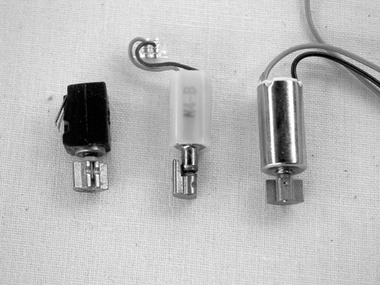
If you’ve elected to scrounge a motor from a broken cell phone or pager, start by making sure that your broken phone or pager has a vibrate function; if so, there will be a tiny, sprightly motor inside with a small weight mounted eccentrically on its shaft (see Figure 22-3 for examples). No vibrate means no motor. Having established that your phone or pager can vibrate, remove the lithium battery, and take out as many screws as you can find. Then use a screwdriver to pry open the plastic housing (there will usually be a single long seam running around the phone’s edge).
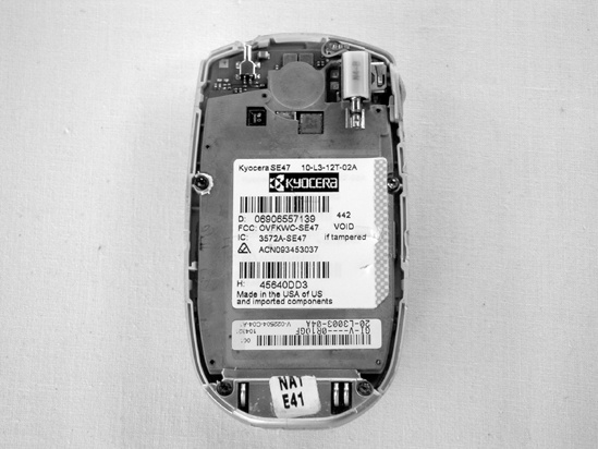
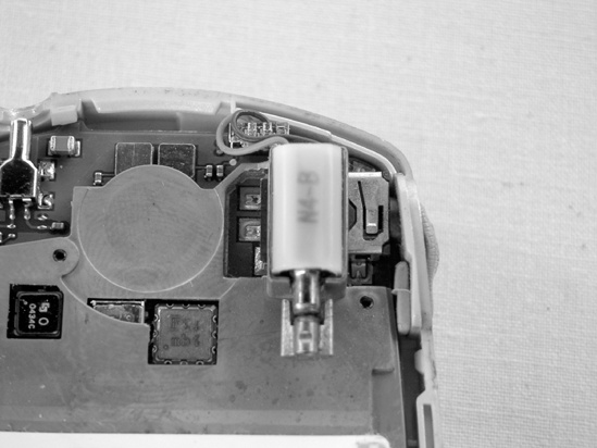
Now that the motor is revealed, as in Figure 22-4, you may find that it is epoxied or otherwise permanently affixed to the circuit board. Fortunately, these are usually mounted near the board’s edge. Use needle-nose pliers to snap that edge off the board and be done with it. If you’re having trouble finding the motor, check the inside of the case (where they are sometimes located in smartphones).
This project is small enough to be entirely mounted on the plastic base of the battery clip itself. Flip the battery clip over; if it has two little plastic spikes on it (intended to help secure the clip to a circuit board; this size battery is often used to provide backup power to the CMOS clocks in older desktop computers), then snip these off with the diagonal cutters from your soldering kit. If your battery clip came with leads attached, snip off the black (i.e., negative or ground) lead. (Make sure to leave enough of the negative terminal’s metal leg intact so that you can solder connections to the ground later.) Conversely, if your battery clip has no leads, then you’ll want to add one to the positive terminal. Measure a 2″ length of wire, strip and tin both ends, and solder one end to the positive battery terminal (this is the one that connects to the metal tongue that curls over the top of the battery holder).
If you bought a motor at the store and it came wired with long leads, you can shorten these to about 1″ (you’ll make them even shorter later). Don’t worry if your motor has no leads; you can solder directly to the terminals in Steps 7 and 8.
Once the battery clip is prepared, smear the bottom with room temperature vulcanizing rubber or any silicone-based household glue, and place the motor across the base’s diameter so that one of the motor’s terminals is about 1/4″ from the negative battery terminal (we’ll call this the motor’s negative terminal henceforward, even though the terminals are basically interchangeable). Be careful not to let the glue foul up the motor’s spinning weight or shaft.
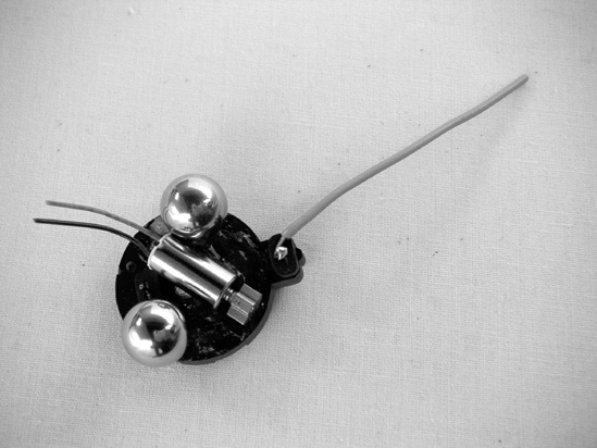
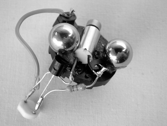
Place one ball bearing on each side of the motor, making sure that neither of the bearings obstructs the motor’s spinning weight or makes contact with a battery terminal or motor terminal. Note that, as in Figure 22-5, ideally the ball bearings are not straight across from each other but grouped a bit toward the tail end of the motor so they form a triangle with the battery clip’s positive terminal; the Jitterbug will ultimately scoot around using the two bearings and the positive terminal as skids. Set the base aside and let the glue dry overnight.
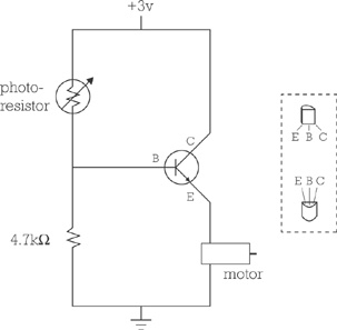
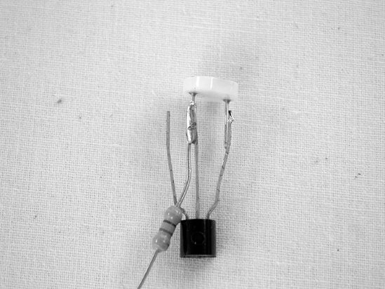
Meanwhile, build the Jitterbug’s brain. As you can see from the circuit diagram in Figure 22-6, this is a very simple circuit, and we’re going to endeavor to keep it as light and compact as possible. This means orienting the components in a slightly unorthodox manner. First, trim down the legs on the photoresistor to about 1/4″. Now hold the transistor with its legs up and flat face away from you, and solder one leg from the photoresistor and one leg from the 4.7k resistor to the transistor’s middle leg (which is its base—check out Figure 22-7 and remember that the transistor’s flat face is resting on the table). Remember that transistors can be a little temperature sensitive; if you aren’t sure that you can work quickly, consider using a heat sink (described in the appendix and illustrated in Figure 16-4 in Building It).
Solder the other leg of the photoresistor and the positive (red) battery lead to the transistor’s right leg (which is its collector), as shown in Figure 22-8. This step can be completed even if the glue is still tacky, but everything after this will have to wait until the glue is dry.
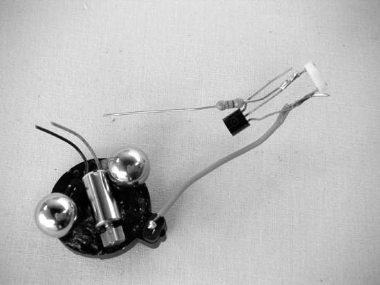
Once the glue is completely dry, carefully bend down the transistor’s remaining leg (the emitter) so it can be soldered to the motor’s positive terminal (the one farthest from the negative battery terminal; see Step 4). Solder the emitter to the motor’s positive terminal. Ideally, the body of the transistor will be more or less even with the edge of the battery clip’s plastic base, as seen in Figure 22-9.
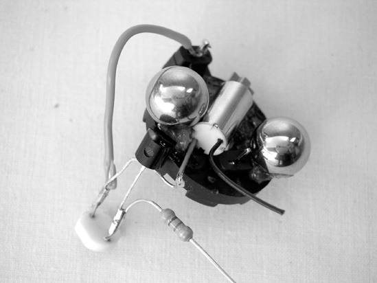
Bend the negative battery terminal over, then bend the remaining leg of the 4.7k resistor down and around so that it connects to the negative motor terminal and slips beneath the negative terminal on the bent battery clip (see Figure 22-10). Solder this leg to both, slide in the battery, and your Jitterbug is ready to run.
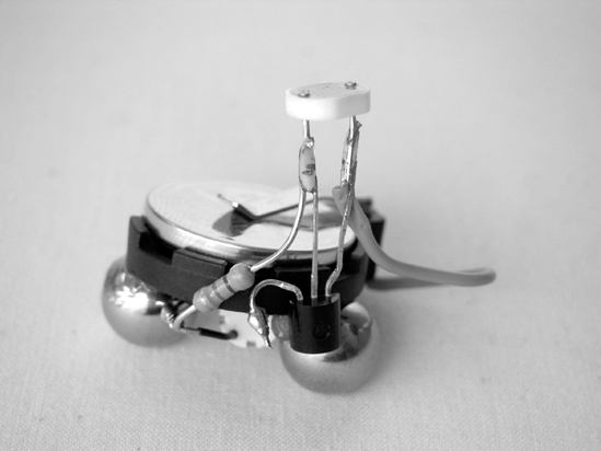
The wires from the resistor and transistor to the motor should be stiff enough to support themselves and the Jitterbug’s photoresistor “eye.” If you’re worried about long-term stability, then use a toothpick to smear a healthy glob of glue on the transistor’s face, and affix it to the edge of the battery clip’s base (see Figure 22-11).