
BrownField Airline is one of the fastest growing low-cost, regional airlines, flying directly to more than 100 destinations from its hub. As a start-up airline, BrownField Airline started its operations with few destinations and few aircrafts. BrownField developed its home-grown PSS application to handle their passenger sales and services.
This use case is considerably simplified for discussion purposes. The process view in the following diagram shows BrownField Airline's end-to-end passenger services operations covered by the current PSS solution:
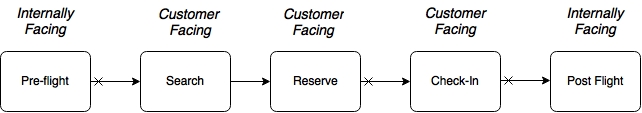
The current solution is automating certain customer-facing functions as well as certain internally facing functions. There are two internally facing functions, Pre-flight and Post-flight. Pre-flight functions include the planning phase, used for preparing flight schedules, plans, aircrafts, and so on. Post-flight functions are used by the back office for revenue management, accounting, and so on. The Search and Reserve functions are part of the online seat reservation process, and the Check-in function is the process of accepting passengers at the airport. The Check-in function is also accessible to the end users over the Internet for online check-in.
The cross marks at the beginning of the arrows in the preceding diagram indicate that they are disconnected, and occur at different timelines. For example, passengers are allowed to book 360 days in advance, whereas the check-in generally happens 24 hours before flight departure.
The following diagram shows the functional building blocks of BrownField Airline's PSS landscape. Each business process and its related subfunctions are represented in a row:
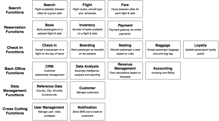
Each subfunction shown in the preceding diagram explains its role in the overall business process. Some subfunctions participate in more than one business process. For example, inventory is used in both search as well as in booking. To avoid any complication, this is not shown in the diagram. Data management and cross-cutting subfunctions are used across many business functions.
In order to effectively manage the end-to-end passenger operations, BrownField had developed an in-house PSS application, almost ten years back. This well-architected application was developed using Java and JEE technologies combined with the best-of-the-breed open source technologies available at the time.
The overall architecture and technologies are shown in the following diagram:
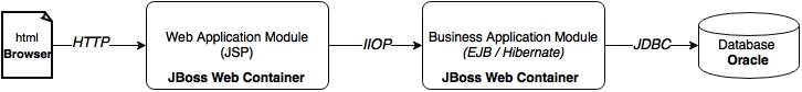
The architecture has well-defined boundaries. Also, different concerns are separated into different layers. The web application was developed as an N-tier, component-based modular system. The functions interact with each other through well-defined service contracts defined in the form of EJB endpoints.
The application has many logical functional groupings or subsystems. Further, each subsystem has many components organized as depicted in the next diagram:
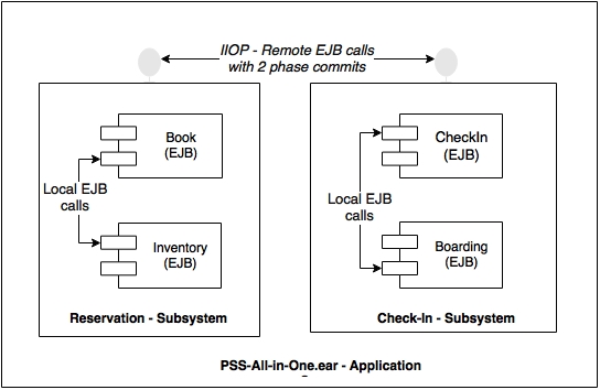
Subsystems interact with each other through remote EJB calls using the IIOP protocol. The transactional boundaries span across subsystems. Components within the subsystems communicate with each other through local EJB component interfaces. In theory, since subsystems use remote EJB endpoints, they could run on different physically separated application servers. This was one of the design goals.
The implementation view in the following diagram showcases the internal organization of a subsystem and its components. The purpose of the diagram is also to show the different types of artifacts:
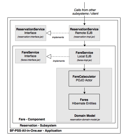
In the preceding diagram, the gray-shaded boxes are treated as different Maven projects, and translate into physical artifacts. Subsystems and components are designed adhering to the program to an interface principle. Interfaces are packaged as separate JAR files so that clients are abstracted from the implementations. The complexity of the business logic is buried in the domain model. Local EJBs are used as component interfaces. Finally, all subsystems are packaged into a single all-in-one EAR, and deployed in the application server.
The application's initial deployment was simple and straightforward as shown in the next diagram:
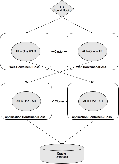
The web modules and business modules were deployed into separate application server clusters. The application was scaled horizontally by adding more and more application servers to the cluster.
Zero downtime deployments were handled by creating a standby cluster, and gracefully diverting the traffic to that cluster. The standby cluster is destroyed once the primary cluster is patched with the new version and brought back to service. Most of the database changes were designed for backward compatibility, but breaking changes were promoted with application outages.