
11 The New Access Network Systems and Enabling Technologies
11.1 Introduction
Different factors have pushed the evolution of the access network from its copper-based architecture to a fiber-based one.
Besides bandwidth increase impelled by the introduction of new services (see Chapter 2, the penetration of ultra-broadband connections stresses the capacity of existing copper cables tosupport a high number of very fast xDSLs. In many cases, copper cables deployed before the diffusion of broadband access presents a non-negligible pair-to-pair interference when xDSL is used. Often, this phenomenon sets a limit to the number of connections possible in a given area, depending on the quality and length of the cables [1].
Moreover, the need of the main carriers to reduce operational cost (OPEX) also drives toward a fiber-optic-based access network. As a matter of fact, optical transmission allows a completely passive access infrastructure to be implemented; much longer spans can be realized, and even the possibility of a delayering of the peripheral part of the network appears Chapter 3
Completely replacing the access infrastructure is perhaps the most CAPEX-intensive operation that an incumbent carrier can face. Such carriers have several million terminations (e.g., in a country like Italy, the network of Telecom Italia has about 20 million terminations) and their copper network reaches almost everywhere, both in cities and in the countryside.
In this situation, it is clear that the deployment cost is the main parameter characterizing a given access solution, and a huge effort is directed toward cost reduction.
In case civil work is needed to deploy new tubes where fiber cables have to be installed, this is by far the most expensive part of the deployment of the new access infrastructure. However, this situation is not so common in North America, Europe, and the most advanced Far East countries, especially in the most populated areas where network deployment is likely to start.
Over the last 20 years, fiber deployment activity has been constant in the major cities [2]. Moreover, even when fibers are not available, tubes are already in the ground, greatly facilitating fiber deployment. For these reasons, we will not deal with civil work in this chapter; readers interested in this aspect can find a starting point in the bibliography [3,4].
Beyond the capacity delivered to the end user and the cost, a variety of other merit parameters characterize an optical access network. Due to the huge investment needed for the deployment, next generation access infrastructure has to be future proof. Thus, the access infrastructure has to accommodate changes in the service bundle offered to the end user and the related evolution of the network equipment. Nevertheless, the investment needed to deploy the new network cannot be made available in a short time.
The convergence of all the telecommunication services toward the Internet paradigm opens the possibility of unifying data transport on the same infrastructure and collecting traditional wireline residential and business users, together with mobile users. Such a convergence is possible to connect the access points of the mobile network (the base stations) to the infrastructure of the wireline. This requires a further penetration to the fiber infrastructure, besides the capability of supporting a large variety of termination equipment.
From the bandwidth management point of view, the copper network assures physical separation among signals belonging to different users in the whole access segment: each user has his own twisted pair. This is a good situation from several points of view. The privacy of the user signal is completely guaranteed because it is impossible to detect the signal belonging to a user from another user terminal. Moreover, the concept of unbundling is strictly related to this characteristic of the copper network, assuring, in this case, perfect separation among signals belonging to different carriers. For these reasons, it would be desirable to reproduce this situation as much as possible in the next generation access network.
11.2 TDMA and TDM Overlay Passive Optical Network
As we have seen in Chapter 3, both due to the need of a careful use of already deployed fibers and tubes and to reflect the broadcast nature of a few key services like IP-TV, passive optical network (PON) is an almost universal choice for the deployment of the fiber access infrastructure.
Using a PON means that the fiber is deployed in a tree topology, often called the optical distribution network (ODN)
Since part of this medium is shared among the different channels, a shared medium access strategy is needed.
While almost all the possible strategies have been proposed, TDMA is by far the most used and all the PON products on the market are based on TDMA.
Recently WDMA has also been considered and a couple of products appeared on the market using this technique.
Differently from TDM PONs that are standardized in detail by ITU-T and IEEE, no consolidated standard still exists for WDM-PON, and this is an obstacle for the development of this kind of access system. In any case, ITU-T also works on WDM-PON standards and a first set of elements have been already defined, even if we are far from a rich standard like those for TDM PONs.
11.2.1 TDM PON Classification
An extended standardization activity has been carried out on TDM-PON by a dedicated group of ITU-T, called full service access network (FSAN) Different standards follow the evolution of both optical technology and switching protocols, passing from APON and BPON, based on ATM, to GPON, capable of conveying multigigabit signals using either ATM or Ethernet protocols, thanks to its adaptation layer called GEM (GPON encapsulation method)
TABLE 11.1 Summary of the Main Parameters of the ATM PONs, Ethernet PON, and GPON

Several North American carriers are looking to GPON to advance their FTTx rollout efforts so that GPON access is under deployment besides the older BPON infrastructure that is present in few local areas.
A different situation exists in Europe, where incumbent carriers generally have not yet committed to a clear strategy. However, a great number of FTTx field tests based on GPON are ongoing.
In the field of Ethernet-based PON, IEEE has emitted an important standard (called GEPON) that has been largely adopted mainly in the Far East. NTT, the major carrier in Japan, and one of the largest telecommunications carriers in the world, began deploying GE-PON-based FTTH access network equipment in 2003. In 2004, the IEEE ratified the IEEE 802.3ah Ethernet in the First Mile specification that fully defined the GE-PON technology deployed by NTT and later adopted by other carriers in Japan and Korea. A synthesis of the main TDM-PON standards is reported in Table 11.1, with some key optical parameters specified for each standard.
In the following discussion, we will mainly focus on GPON, due to its adoption in North America and probably in Europe also, where it is quite improbable that an ITU-T standard would be neglected in preference for an Ethernet-based GEPON.
Several considerations on transmission impairments and other elements are, however, common between GPON and GEPON
11.2.2 GPON architecture and Performances
The GPON standard [5], as all other standards for TDM-PONs, is based on unidirectional transmission, conveying downstream and upstream signals on different wavelengths on the same fiber. In this case, the effect of reflection is limited by the great wavelength separation between the two signals.

FIGURE 11.1 GPON standard wavelength plan including the case in which the video overlay is used
In addition to the GPON version with two wavelengths, there is a GPON standard conveying two downstream wavelengths. One of them (1490 nm) is used to convey the GPON downstream signal, the second wavelength (1550 nm) is conceived for the distribution of analog CATV. This solution has been adopted in North America where CATV is practically the TV standard, and this solution allows the customers to maintain their home TV sets. The frequency plan of the GPON standard is shown in Figure 11.1.
Under a link budget point of view, GPON standard defines different link budget classes, whose parameters are reported in Table 11.1.. A new class of performances will probably be standardized called C+ with a link budget higher than 33 dB.
Splitter loss depends mainly on the number of output ports on the splitter and adds about the same loss whether traveling in the downstream or upstream direction. Each splitter configuration is assigned a particular maximum split ratio loss, including connectors, defined by the ITU G.671 standard and Telcordia GR-1209.
When using the 16 or 32 splitting ratio, the standard completely defines all the needed splitter characteristics. Since this is not true for 1 × 64 splitters, network designers must use a single 1 × 2 splitter interfacing two 1 × 32 splitters to make up the 1 × 64.configuration
11.2.2.1 GPON Transmission Performances
Using Class B optics only leaves 5.35 dB of propagation loss. Therefore, even with the best fiber access infrastructure, where the spectral attenuation can be assumed to be 0.31 dB/km, only a 17.25 km PON network is achievable without including any of the connectors within the local exchange.
A GPON reach of 20 km is specified for class B+ and C GPONs.
It is very interesting to investigate the physical effects thwarting GPON transmission, since the situation is much more complex than in the WDM-PON case.
In the case of A and B classes, the GPON span is essentially limited by the power budget. It is to be noted that in optical access networks, reducing the ONU cost is a key issue. For this reason, in A and B classes, GPON Fabry–Perot laser diodes (FP) are generally used at the ONU, while a PIN photodiode is present at the OLT.
FP lasers are multimode lasers, so that mode partition noise due to the mode statistical fluctuation of the optical source arises [6]. This effect, if not, suitably reduced by a careful design of the lasers, can greatly limit the GPON span. For these reasons, the key characteristics of FP lasers to be used in GPON are specified in the standard, so as to be able to match the required performances.
In the case of B+ and C classes, the situation is different. As a matter of fact, modal dispersion arises in the downstream link [7], constituting a first span limitation. In order to face this effect, two ways are possible. The most diffused solution is to substitute FP with distributed feedback lasers (DFBs), accepting a cost increase. Specific DFB lasers are designed for use in.GPON, whose design requirements are relaxed with respect to similar devices used in dense wavelength division multiplexing (DWDM) long haul systems in order to reduce the cost.
As a matter of fact, perfect single mode operation is not strictly needed to eliminate modal dispersion. As an alternative to DFBs, the adoption of Electrical Dispersion Compensators (EDC) in the OLT has been also proposed and demonstrated [8].
It is interesting to observe that standard forward error correction is practically ineffective to correct the effects of modal dispersion. As a matter of fact, when the fluctuation in the modal structure of the source causes errors, they are concentrated in long bursts. It is possible to design a code conceived to correct long bursts of errors [9], but these codes are generally not used in optical communications for the decreased effectiveness in correcting random errors.
As far as the downstream is concerned, in order to achieve the required power budget with the standardized classes of emitted power, the ONU detector has to be an avalanche photodiode (APD) This also impacts on the cost of B+ and C GPON classes.
Another important phenomenon appears when the analog video overlay is present. In this case, due to the relevant power of this new channel, the Brillouin effect arises [10] so that a careful design of the optics is needed to reach the specified performances.
11.2.2.2 GPON Frame and Adaptation Protocol
As in the case of all implementations of the TDM-PON, also in the GPON, different users are assigned different time-slots in a TDM frame and bidirectional transmission on the fiber infrastructure is realized using different wavelength so that only a single fiber tree is needed, as shown in Figure 11.2.[11].

FIGURE 11.2 Topology of the set of GPON ODNs managed by a single OLT.
In this figure, a realistic OLT is shown where a set of PONs is managed by the same equipment. Hundreds of PONs can be terminated on the same OLT, optimizing on one side real estate and power consumption, and on the other, the packet multiplexing operated by the OLT switch.
Due to the topology of the ODN, a further issue arises: the different end users are at different distances from the splitter at the tree branching point. In this condition, each end user device (the ONU), has to transmit with a certain delay with respect to the reference time-frame in order to allow correct reconstruction of the signal at the branching splitter. This delay is continuously updated by a particular PON control procedure that measures the optical distance between the ONU and the branching point and drives the ONU asynchronous transmission.
This procedure is implemented into the physical layer PON processor that is generally a part of a single chip running all the physical layer protocols, comprising maintenance and critical alarms.
Another important element of the logical architecture of the GPON is the GEM: the GPON enveloping method, allowing almost every packet-oriented format to be conveyed through the PON, without the inefficiencies that were characteristics of ATM, that were deputed to do this in APON and BPON [11].
The layering of a PON network transporting Ethernet over ATM, native Ethernet and Ethernet over GFP (generic framing) is shown in Figure 11.3, where the role of the GEM is evident.
Another important physical layer procedure implemented on all the GPONs is dynamic bandwidth allocation (DBA) [12,13].
DBA allows upstream timeslots to grow and shrink based on the distribution of upstream traffic loads and operates on a timescale of milliseconds. Of course, the total of all times-lots cannot be greater than the length of a single upstream frame.

FIGURE 11.3 Layering of an access network based on GPON transport.
GPON Downstream frame is divided in transmission containers (T-CONTs), that are the upstream timeslots. There are much more T-CONTs than ONUs and DBA works exploiting this property.
An ONU must have assigned at least one T-CONT, but most have several T-CONTs whose number is managed by the DBA following the bandwidth needs of the different users.
Besides a drastic enhancement in the upstream bandwidth exploitation, DBA also allows a possible service level agreement (SLA) with a PON customer to be managed and controlled.
This is a very important characteristic, allowing a shared medium-based transmission system to be used to serve business customers with high requirements.
The ITU-T standard does not prescribe the specific DBA algorithm to be used, but defines two classes of possible algorithms.
If one of the so-called status reporting (SR) DBA is used, all ONUs report their upstream data queue occupancy, to be used by the OLT calculation process. Among the T-CONT assigned to the same ONU, each individual element may have its own traffic class, corresponding to the SLA of the conveyed service. By combining the queue occupancy information and the provisioned SLA of each T-CONT, the OLT can effectively optimize the upstream bandwidth allocation.
If, on the other hand, a non-status reporting (NSR) DBA is used, ONUs do not provide explicit queue occupancy information. Instead, the OLT estimates the ONU queue status, typically based on the actual transmission in the previous cycle.
For example, if an ONU has no traffic to send, it transmits idle frames during its allocation period. The OLT would then observe the idle frames and decrease the bandwidth allocation to that ONT in the following cycle. In the opposite case, the OLT constantly increases the allocation size until idles are detected, slowly adjusting to growing traffic.
Under a performance point of view, SR algorithms are superior in achieving high efficiency, as can be easily understood. However they are more complex to implement, also for the need of managing the return signals from all the ONUs.
11.2.2.3 GPON Capacity per User
The evaluation of the GPON capacity per user is not simple in that it depends critically on the bundle of services provided to the users. As a first step, let us assume that all the users have the same service profile composed by a.500.Mbit/s broadcast signal and a set of unicast services.
Let us start with an evaluation of the downstream capacity per user.
Due to the intrinsic broadcast capability of the GPON fiber infrastructure, the broadcast signal can be delivered in a dedicated part of the downstream TDM frame that will be received by all the end users.
The remaining part of the downstream frame (2.Gbit/s in our example) has to be divided among the users. Assuming a splitting ratio of 32, a bare physical bandwidth of 62.5.Mbit/s is assigned to each user. However, in order to evaluate the effective bandwidth per user, we have to take into account the statistical multiplexing at the end of the OLT that acts on the low activity of the sources and the statistical multiplexing at the ONU switch that grooms signals.
In the case of a realistic bundle of services Chapter 2 statistical multiplexing at the OLT allows a gain factor of the order of 4–5.over the bare physical bandwidth assigned to the user.
The statistical multiplexing at the ONU guarantees, for sure, that the ONU port can manage, with its queuing capacity, peaks of traffic of the order of the maximum available physical bandwidth with a very low packet rejection probability.
Thus, it can be said that thanks to the low services activity and statistical multiplexing inside the ONU and the OLT, the user has the same system experience in terms of service quality and speed that he would have with deterministic TDM multiplexing and service activity equal to one with a reserved bandwidth of about.300.Mbit/s completely dedicated to point-to-point services.
As a matter of fact, we have to remember that every broadcast service can be distributed in a separated broadcast channel exploiting the topology of the ODN.
In our case, besides the perceived bandwidth of 300 Mbit/s, a 500 Mbit/s bandwidth is also used by streaming broadcast services.
The result of these calculations could change if the downstream signal is mainly constituted by unicast video streaming (e.g., Video on Demand [VoD])
Increasing the VoD, it could be possible that the OLT grooming is not yet enough to maintain such a highly perceived bandwidth. However, it is to take into account that DBA can be applied not only to the upstream, but also to the downstream, and it is effectively done in several GPON designs.
In the presence of several VoD channels, DBA is particularly useful, since it permits the allocation of a reserved bandwidth to the VoD service exclusively where and when it is present.
We can try to quantify the effectiveness of the DBA, in the downstream, in two ways: either by maintaining the low activity bundle we have supposed at the beginning and by trying to evaluate as the user perceived bandwidth increases, or by adding to the low activity scenario, a relevant number of VoD channels and by trying to calculate the maximum number of VoDs compatible with the overall performances required by the network.
The first evaluation can be done with the tools of the queue theory, and it results that assuming Poison processes for the start of a call on the different services and an exponential service duration, the gain related to SR DBA is something between 2 and 4.
This means that if the ONU is sufficiently equipped to manage this situation, the perceived capacity evaluated is around 600 MHz.
However, this perceived bandwidth is related to the low activity bundle, and is not useful. Generally, carriers are more interested in the possibility of accommodating the VoD without changing the GPON hardware.
Frequently, in front of a market forecasts for the fruition of new services, the carrier is interested in evaluating the maximum possible penetrations of the VoD before the need of increasing the physical access capacity arises.
Since this type of evaluation is quite instructive, we will follow it in certain detail, exposing an evaluation that a tier one carrier has shown at a conference in the framework of a discussion on the GPON capacity to face the pace of fast traffic growth [14].
The calculation refers to a typical urban area served by a central office. In the area, there are 400 users divided into three classes:
Thirty percent of the users (120 units) have only telephone service; this means that they have an IP phone; the average traffic produced by such users is 30 mErlang per customer.
Thirty percent of the customers (120 units) have the same telephone service considered above, plus a fast Internet browsing service with a peak guaranteed bandwidth of 1 Mbit/s.
Forty percent of the users (160 subscribers), on top of the service characteristics of the second class, have IP-TV service.
The different services are implemented so that the IP phone is coded for a peak bandwidth of 26 kbit/s while the IpTv is coded, both for the standard and the high definition channels, within a bandwidth of 16 Mbit/s. This is a conservative hypothesis, mainly assumed to simplify the calculation. However, almost nothing changes with a more accurate modeling of the IpTv bandwidth.
Finally, it is assumed that in the peak hour, 50% of the subscribers who have IpTv will use it It is to take into account that the IpTv is a multicast channel, thus the overall traffic for IpTv is, on an average, 0.5 Erlang per customer.
Carrying out classical traffic computations, the average traffic partition in the peak hour is obtained as shown in Figure 11.4..This figure also shows the efficiency and the weakness of current GPON downstream bandwidth management.
As a matter of fact, if low activity services should be added, there is plenty of bandwidth to support a good diffusion. The effective browsing time can be halved as far as the transmission speed is concerned, for all the users, consuming only a small part of the available bandwidth, and even a doubling of the number of IpTV customers will present no problems.
The problem comes when services with high activity, as VoD or pair-to-pair video streaming, are considered.
For example, the residual capacity allows 70 contemporary VoD channels to be distributed, and if there is an important penetration of VoD, with more than one VoD-enabled TV in high spending families, this figure would not be enough.
However, this scenario does not seem to be realistic in the near future, thus, with the service bundles that can be envisaged, the GPON seems to have quite a sufficient downstream capacity.
Let us now consider the upstream capacity. Even eliminating broadcast, presently, several services require less upstream bandwidth with respect to downstream, but in the near future, this trend could change due to the growing importance of point-to-point services.
In the case of the upstream, the user activity is even smaller that the average activity of the downstream, the ONU performs statistical multiplexing on the line and the OLT queuing guarantees the absence of lost packets.
Moreover, in the downstream direction, the DBA allows peak requests from specific ONUs to be allocated using the capacity flexible assignment.
Thus, on top of a bare average physical bandwidth per user equal to about.39.Mbit/s, we have to take into account a gain equal approximately to 4–5 from the ONU and a further gain of about 2 coming from the DBA.
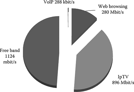
FIGURE 11.4 Occupied and free bandwidth in our example of GPON installed in a populated area.
At the end, assuming that the ONU gains a bit less than the OLT and that an SR DBA is used, the user has the same system experience in terms of service quality and speed that he would have with deterministic TDM multiplexing and service activity equal to one with a reserved bandwidth of about 320 Mbit/s available.
This calculation seems strange, but it is a fact that generally, GPON users do not perceive the transmission capacity unbalance of the network.
11.2.2.4 Functional Structure of a GPON OLT and ONU
In order to implement, with a suitable hardware and software structure, the functionalities we have seen, the GPON OLT and ONU have rich functional structures that assure both control and management functionalities and quality of service (QoS) implementation [15].
The functional structure of the OLT is shown in Figure 11.5..From a functional point of view, the OLT is divided into three areas that are often referred to as shells.
The core shelf is the functional area terminating the physical layer on the side of the ODNs We have to remember that each OLT generally terminates several GPONs, also a few hundred in the case of big OLTs.
Thus, it is important to design this shell in a compact and functional way. Besides the physical interfaces with transceivers and all the transmission and detection electronics, the multiplex and demultiplex functions that are needed to create and terminate the GPON frame are also located in the core shell.
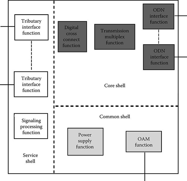
FIGURE 11.5 Functional representation of a GPON OLT.
The ranging protocol needed for the correct synchronization of all the signals sent toward the splitting center is also part of the interface functionalities.
Besides this transmission function, the core shell contains the so-called OLT Cross Connect. Originally, it was a digital cross connect since in the OLT, the SDH/SONET standard was applied.
In more modern OLTs, it is common for a carrier class switch to function as a cross connect inside the OLT. It has the role of grooming all the traffic coming from the user with lines that terminates in the OLT so as to best exploit the backhauling lines of the OLT. The DBA is managed in this part of the OLT.
The common shell includes all the management and maintenance functions, and from a hardware point of view, the power supply also belongs to this shell.
Finally, all the functionalities related to data back hauling are located in the service shell. Among them, we can note the termination of the core network signaling and the interfaces with the backhauling lines.
Also, the functional structure of the ONU, plotted in Figure 11.6, can be divided in the same shells, where now the service shell is toward the home network and the user appliances.
The partition of the main ONU functions among the three shells is quite recent and is shown in Figure 11.6.

FIGURE 11.6 Functional representation of a GPON ONU.
11.2.3 NG-PON Project and the GPON WDM Overlay
One of the main targets of tier one carriers is to burst individual fruition of services with respect to broadcast fruition (that in the field of television means VoD with respect to Broadcast IpTV)
This is because broadcast can also be done, even with a smaller bandwidth, by means of satellites and traditional terrestrial television, and the customers are used to having the first for steadily decreasing prices, and the second for free.
Moreover, where a diffused cable TV exists, like in the United States, the IpTV is perceived by the customers as something they already have and it is difficult to obtain from it the marginal increase that the carriers need.
Finally, the importance that pair-to-pair customer activities are assuming, is something that puts value in the intrinsic bidirectional nature of the telecommunication network; thus, it can be a good opportunity for carriers.
This consideration also points the attention toward the weaker aspect of the GPON, as we have seen in the example of the last section.
Thus, a great amount of work is being undertaken in the standardization bodies (mainly in the ITU-T FSAN group) to standardize one or more versions of the so-called NG-PON (Next Generation PON)
Since the deployment of the GPON in vast areas is considered certain, all the work is based on the assumption that the new access transmission equipment, while providing a much greater capacity, exploits the same ODN deployed for GPON.
Besides this simple, but important requirement, a group of carriers in ITU-T have proposed that the entire standardization of the NG-PON be based on a much more severe set of requirements targeting a smooth and gradual transition from GPON to NG-PON. This set of requirements, that can be called Compatibility Conditions (CC), can be synthesized as follows [16]:
Coexistence:NG-PON systems need to coexist on the same fiber with today’s GPON
Allows existing GPON subscribers to be individually migrated to NG-PON on an as-needed basis without disrupting other users on the PON
Relies on the deployment of G.984.5 compliant ONTs today and NG-PON systems using G.984.5 enhancement band wavelengths
Digital capacity: At a minimum, the capacity of NG-PON systems should be 10 Gbit/s downstream and 2.5 Gbit/s upstream. Alternatively, a system that overlays multiple GPON systems on the same ODN is also considered an acceptable solution.
Loss budget: At a minimum, NG-PON is expected to operate over “Class C” ODNs (30 dB loss) Class C++ (>32 dB) operation with optical pre/post optical amplification is also considered a possible solution for long reach access.
Split ratio: A minimum of 64 ways split should be supported, but for some applications (e.g., office consolidation) a 256-way (or higher) split may be needed. In the last case, optical amplification is suggested to overcome power budget limitations.
Reach: A 20 km physical reach through a passive ODN is required and at least a 60 km reach using optical amplification is recommended.
If the CCs greatly simplify the carrier problem in evolving from one PON generation to the next, they pose a difficult problem to the equipment vendor.

FIGURE 11.7 Architecture of the WDM overlay of a certain number of GPONs with colored interfaces. In this case, the ODN has two branching points: a WDM branching and a GPON branching.
The simpler way to respect the CCs seems to be through the exploitation of WDM technology starting from the ITU-T standard allocation of the fiber bandwidth in the access area summarized in Figure 11.1.
The idea is to use the empty bandwidths to allocate, besides existing GPONs, other GPONs that differ from the standard today only for the value of the upstream and the downstream wavelengths.
An example is the use of the 1505–1545 bandwidth (i.e., the great part of the C band) to convey a certain number of “colored” GPON on the wavelengths of the DWDM standard.
The network architecture coming out from this idea is plotted in Figure 11.7.
In order to try to smooth the traditional difficulties that are always present when designing a DWDM bidirectional system, the considered bandwidth has to be divided into two sub-bands (upper and lower wavelengths) and a guard interval is maintained between the bandwidths.
Let us assume that a 200 GHz spacing is used to simplify the optical system design, and that a guard interval of 400 GHz is maintained between the upstream and the downstream optical bandwidths.
Thus, it results that we can put 10 channels in the upstream bandwidth and 10 channels in the downstream bandwidth, using exactly the same ODN and without in any way disturbing the already existing GPON.
This solution is very good for the fidelity to (CCs), that means to guarantee an easy adoption by the carriers, and this, for sure, provides a good way of upgrading the network in pace with the penetration of broadband services.
On the other hand, functionally, the capacity delivered to a single user is the same as the GPON, unless more than one ONU is allocated at the user’s premises.
Moreover, and definitely much more important, the overall cost of this solution heavily depends on the cost of the DWDM colored interfaces and on their market.
As a matter of fact, while a traditional PON has a single OLT interface for each served ODN, this version of the NG-PON has one interface for each served wavelength.

FIGURE 11.8 ITU-T standard definition of the average attenuation of an SSMF fiber with the names of the standard bandwidth and the standard CWDM channels. The water absorption peak is evidenced by the dashed line.
A way to alleviate the problem related to the interface cost is to adopt CWDM, whose standard grid is reported in Figure 11.8..As is evident from the figure, the water peak is unfortunately located around 1400 nm in the SSMF, almost the only fibers that are installed in the access area, which is just in the middle of the upgrade band (see Figure 11.1)
This renders the CWDM almost useless for use, since the number of frequencies that can be used is really small.
If the condition to interact with an already existing GPON in the same ODN is removed, the situation changes completely. In this case, the use of CWDM is quite effective, allowing eight colored GPONs (16 wavelengths) to be superimposed on the same ODN so creating a simple and powerful structure that takes advantage of the simplicity of the transmitter and receiver that are sold in great volumes for datacom and other applications.
However, the main problem, in term of cost of this architecture, is the need for colored sources both at the OLT and at the ONU. As a matter of fact, not only colored (and temperature stabilized in the DWDM case) sources have a much higher cost with respect to the simple sources used in standard GPON, but the management of the spare parts that have to be available for fast maintenance in case of failure is more complex, increasing the OPEX related to these equipments.
This problem can be removed in two ways. The first is to introduce a sufficiently cheap tunable laser suitable for this application.
In this case, the management of spare parts is the same as in the gray case. Today, tunable lasers, existing only for DWDM applications, are still too costly, but the situation could change.
As a matter of fact, on one side VCSELs seem to be almost ready for application in the third window, and tunable VCSELs have been obtained and tested in labs experiments [17].
On the other hand, the technology of lasers bars Chapter 5 could open the way to the realization of a CWDM tunable laser, which is an impossible task if designed with traditional tunable architectures.
The second method to solving the problem of having colored interfaces at the ONU is more on the system side.
At the OLT, 2N lasers (one for each different ODN terminating on the OLT) generate 2N wavelengths that are divided into upstream and downstream bandwidths. Downstream wavelengths are directly modulated and transmit the signal toward the end users.

FIGURE 11.9 Implementation of a colored ONU in a PON using WDM multiplexing (either a WDM overlay of GPONs or a real WDM-PON) using the injection locking of a Fabry–Perot laser diode with a seed coming from the OLT at the correct wavelength.
Upstream wavelengths are transmitted unmodulated up to the end user. Every ONU is equipped with an identical, colorless Fabry–Perot Laser.
When an unmodulated external optical beam is injected into the cavity of an FP Laser, it will experience the internal gain from the semiconductor material. This process results in a reflected and amplified signal that contains the data modulation imparted by the pump current.
Since the injected signal can be much larger than the internally generated spontaneous noise, the majority of the optical output power will be at the wavelength of the injected signal. The normal multiwavelength spectrum of the FP is transformed into a quasi single-wavelength spectrum similar to that of a DFB laser. This narrowband output signal can then be efficiently transmitted through a WDM communication channel. The external injected wavelength is called the “locking” or “seeding” wavelength.
This mechanism is shown in the plot of Figure 11.9.
It is to be noted that since the upstream signal is amplified by the FP gain, it is possible to design the system so that it is not disturbed by small reflections of the seed arriving in the downstream direction. Last, but not least, a single AWG can be used in this system, processing the signal in two directions. This is possible with the so-called cyclical AWGs [18] that are devised to contemporary multiplex one bandwidth in one direction and demultiplex the other in the other direction.
In this way, a colorless FP is forced to emit a colored signal by the incoming wavelength containing the wanted modulation and constituting the upstream signal coming from the ONU. It can be noted that in this WDM-PON architecture also, every used wavelength is emitted by a colored source. However, all the sources are collected in the OLT, and the ONU is colorless.
Thus, the management of the spare parts and in general the system maintenance is simplified.
11.2.4 XG-PON
Another straightforward idea in preparing the network to meet a great increase in bandwidth request is simply to increase the bit rate from 2.5/2.25 Gbit/s to, for example, 10/2.5 Gbit/s.
This is the way that has been preferred for standardization by FSAN.
After finalizing the XG-PON1 basic specification, FSAN successfully carried it to ITU-T and the set of requirements was standardized as in the G 987 series.
The important choice in anticipating the standardization of the architecture relying on an higher bit-rate to achieve a greater capacity was not done arbitrarily, on the contrary, all the solutions presented by FSAN members or known in literature have been evaluated especially from the point of view of the asymmetry between the real per user bandwidth, and the XG-PON has been evaluated as the most suitable with the most common bundles of services [19].
Moreover, the design has been built on the requirements of the CCs, so that an XG-PON can be installed on an ODN where a normal GPON is running without disrupting the GPON operation.
These requirements have conditioned the choice of the spectral plan of the XG-PON, bringing us to the solution reported in Figure 11.10.
Three classes of XG-PON are foreseen even if the standardization mainly concerns the first class, which is considered the first to be deployed.
XG-PON1
NRZ both upstream and downstream
Downstream, R = 9.95328 Gbit/s
Upstream, R = 2.48832 Gbit/s
Maximum fiber distance: 20 km, with options of 40 km (in case with optical amplification)
Split ratio up to 1:256
Loss budgets: 29 and 31 dB
FEC in the frame to help correct transmission both upstream (RS(248, 232) and downstream (RS(248, 216)
XG-PON1 Extended
As XG1-PON, but with a longer reach; this solution will probably need the so-called extenders, which are amplifiers suitable for remote power feeding
XG-PON2
Has to target a downstream capacity of 40 Gbit/s

FIGURE 11.10 Wavelength plan of the XG-PON1.
All the main elements that are present in the GPON are reproduced and adapted for the XG-PON1; thus, the adaptation for higher levels packets is the GEM, suitably adapted to work with the different TDM frames of the XG-PON1 (e.g., it contains an FEC that was not present in the GPON frame), ranging protocol managed by the OLT to prevent collision in the splitting points, DBA both in upstream and in downstream.
On top of these characteristics, the XG-PON1 standard presents some aspects of novelty with respect to the GPON; among those a much more efficient security, with internal mechanisms for ONU and OLT registration, and a great attention to power consumption.
11.3 WDM Passive Optical Network
During the first phase of the NG-PON project, FSAN has also considered the possibility of accessing the shred medium through wavelength division multiplexing.
A simple architecture of a WDM-PON is shown in Figure 11.11..The OLT, placed in the local exchange, is constituted by an Ethernet switch managing a certain number of PONs and allowing grooming and QoS protocol management, and by a set of optical interfaces, one for each end customer. A different wavelength is associated to each end customer, so that the OLT must have WDM-capable interfaces.
In order to avoid problems with reflections from the fiber infrastructure, unidirectional transmission is generally considered. Thus, a fiber pair is needed in each branch of the PON infrastructure. A couple of athermal mux/demux is placed in the branching point, and every signal is terminated at the final user site with an ONU tuned on the user wavelength.
The wavelength plan used in this architecture depends on the adopted WDM technique. If the CWDM standard is used, generally, no more than 16 wavelengths can be adopted.

FIGURE 11.11 Architecture of a WDM-PON using unidirectional fiber transmission. The CWDM wavelengths are assumed in the figure.
This is due to the fact that common fibers have an absorption peak around 1390 nm, due to OH ions, and as shown in Figure 11.8, where the absorption profile of an SSMF fiber (ITU-T G.652) is superimposed on the CWDM frequency standard. Assuming a sensitivity of −18 dBm of the receiving PIN, a transmitted signal power of 0 dBm and a loss of 5 dB from the mux/demux, an ODN attenuation smaller than 0.65 dB/km is needed in order to achieve a reach of 20 km. This requirement is not fulfilled by the CWDM channels that are around 1390 and 1410 nm, thereby reducing the number of useful channels to 16.
Adoption of the CWDM standard has several advantages, from the possibility to use low cost, robust transceivers, which are produced in very high volumes mainly for datacom applications, to the availability of low cost athermal mux/demux.
If a high wavelength number is to be used, DWDM is needed. In this case, it is easy to reach the number of 32 or 64 wavelengths in the third fiber transmission windows, at the expense of a higher interface cost.
One of the potential problems in deploying the WDM-PON architecture depicted in Figure 11.11, is the presence of colored ONU optical interfaces. As a matter of fact, every ONU receives and transmits a different wavelength. The management of 16 different ONUs during network deployment (in the case of CWDM-PON) can increase operational costs, due both to spare parts management and in-field maintenance.
Naturally, in this case also, the need of colored interfaces can be eliminated either by using tunable lasers or by injection locking in FP Lasers.
11.4 WDM-PON versus GPON and XG-PON Performance Comparison
At this point, it is interesting to compare the WDM-PON and GPON on one side, where WDM-PON is based on CWDM and Gigabit Ethernet (GbE) channels on each wavelength, and WDM-PON and XG-PON on the other side, where WDM-PON is based on CWDM again, but each wavelength carries a 10 GbE channel, which we will call XWDM-PON.
In this section, we will limit our analysis to an architectural and performance comparison since an economic comparison is critically dependent on commercial and industrial strategies, and it is quite impossible to do if on one side there is a commercial product and on the other, a system under prototyping.
However, even without an explicit calculation, the main point driving the cost structure of WDM-PON and GPON/XG-PON will be clear.
In order to correctly carry out the comparison, we have to concentrate our attention on a single WDM-PON architecture; here we will consider in both cases the simple architecture of Figure 11.11, where colored ONUs and unidirectional transmission are used.
Capacity: GPON versus WDM-PON
The capacity per user of a WDM-PON is easily evaluated: a single wavelength is dedicated to each end user. In general, a GbE signal is transmitted on each wavelength, assigning a capacity of 1.25 Gbit/s to each end user. It is worth noting that the WDM-PON has no particular advantage if part of the signal is constituted by pure broadcast (e.g., conventional IP-TV): the broadcast signal has to be replicated by the OLT on every wavelength and independently sent to each user.
The evaluation of the GPON capacity per user is not so simple as we have seen in the dedicated section.
Using the example we have cited there when we calculated the GPON expansion capacity, let us try to carry out the calculation also for the WDM-PON.
Since we have to feed 400 customers through 32 ONUs placed in the basements of the buildings of the area, we use the fiber to the building (FTTB) configuration. In the case of WDM-PON, we will have 16 ONUs, thus every ONU will have twice the traffic load.
Since the WDM-PON is symmetric, the evaluation is only for the downstream, which is the most critical direction.
Repeating the traffic evaluation in this case, we will find that each ONU that is served by a GbE channel has to manage a traffic constituted by 500 Mbit/s of broadcast IpTV, and a total of 73.5 Mbit/s of point-to-point traffic constituted by 18 kbit/s of Ip phone (this is naturally an average value since it is lower that the base Ip phone rate), 17.5 Mbit/s of web browsing, and 56 Mbit/s due to individual video programs.
The total amount of traffic is about 574 Mbit/s.
We have to take into account that the efficiency of the GbE channel should not be pushed to the limit as it might risk congesting the far end switch. Let us image reaching a 68% efficiency of the GbE, which is a net capacity of about 0.81 Gbit/s.
The free capacity per ONU is in this case 236 Mbit/s and globally 3.7 Gbit/s. If we want to evaluate how many VoD channels we can allocate, it would be misleading to divide 3.7 Gbit/s per 16 Mbit/s, since in this case it is not possible to distribute in a dynamical way, the bandwidth among different groups of users as is possible in the case of a GPON.
The only result that can be considered is that with the WDM-PON, it is possible to open 14 VoD channels for each of the 16 ONUs. The result is that the comparison between the two architectures is quite difficult.
If the service penetration is uniform, and corresponds to an area covered by the uniform central office from a social point of view, the WDM-PON is much more effective in delivering point-to-point services that have high activity. If the penetration of the service is very inhomogeneous, the WDM-PON advantage gets smaller and smaller.
Capacity: XG-PON1 versus XWDM-PON
Under a qualitative point of view, the situation is exactly the same as we described in the previous section. The relevant difference is that if such very high capacity systems have been adopted, this means that the penetration of high capacity and high peak bandwidth services are already here.
In this case, the much higher total capacity of the XWDM-PON gets, for sure, a better result from a capacity point of view.
However, we must not forget that this is not for free, and whatever technology solution will be found to decrease the cost of the XWDM-PON interfaces, a certain price difference should always exist between the two categories of systems.
Security and unbundling: Both cases
WDM-PON assigns to each user, a dedicated wavelength. This is not exactly the same as the dedicated physical carrier that is assigned to the user in the copper network, but the situation is quite similar. Due to the presence of mux/demux in the branching point, every ONU receives only its own signal, so that a user cannot gain access to signals directed to other users. Moreover, a wrong working of a single ONU cannot influence the signals of other users, thus a good degree of security is guaranteed.
As far as unbundling is concerned, different wavelengths could be assigned to different carriers if a suitable mechanism is implemented in the OLT. This is not a physical separation exactly, because the physical layer is common among different carriers and data security is guaranteed by wavelength separation.
In the case of GPON, each user receives the signal directed to all the users so that it is possible to gain access to the signal directed to another user by simply working on the ONU. Moreover, if the ranging protocol of a single ONU does not work, the wrongly synchronized signal interferes with the signals from other ONUs in the branching point damaging other users.
As far as unbundling is concerned, it is practically impossible using GPON, unless virtual unbundling is considered. In this case, an amount of bandwidth in the shared downstream channel is assigned to a competing carrier under a defined SLA.
Fiber utilization: Both cases
Due to the fact that bidirectional transmission is used in the GPON case, while in our example WDM-PON unidirectional transmission is adopted, the fiber infrastructure is clearly better exploited by the GPON. As shown in Section 11.3, unidirectional transmission can be used in WDM-PON, but comes at some cost. As a matter of fact, in order to achieve a sufficient branching ratio, DWDM is needed, for example, 32 channels with a channel spacing of 100 GHz. A possible design can individuate two different bandwidths to be used upstream and downstream. They can be separated by a gap of about 800 GHz to prevent destructive interference from reflections. In this way, a branching ratio of 16 can be achieved. However, 100 GHz channel spacing requires cooled DFB lasers to be used both in the ONU and in the OLT. This fact, besides the greater cost of the mux/demux, clearly influences the cost of the system. In order to cope with this problem, the use of a WDM comb derived from the filtering of a single broadband noise source [20].has been proposed, but it is not clear yet if real cost advantage is achieved.
Optical link budget: WDM-PON versus GPON
The transmission scheme of WDM-PON is quite simple: attenuation is given by the loss of the mux/demux and by fiber propagation (taking into account connectors, patch panels, and other signal losing elements that can be present in the access infrastructure)
Focalizing on CWDM-PON, standard CWDM optics can assure a transmitted power of 0 dBm, while the receiver sensitivity depends on the used detector. Using a PIN, the sensitivity at 1.25 Gbit/s (assuming that a GbE is transmitted) can be about.−18 dBm. This number increases to about.−28 dBm using an APD.
Assuming the use of 16 wavelengths, the worst channel experiences an attenuation of about 0.9 dB km. Adding the other contributions and a system margin, we can assume a loss of 1.3 dB/km. Inserting these numbers in a very simple link budget evaluation, we obtain 10 km using a PIN at the receiver and about 22 km with an APD.
In the case of GPON, the link budgets are standardized in different GPON classes and are reported in the GPON description section. In any case, classes B and C power budgets are of the same order of magnitude as the budgets evaluated in the case of the WDM-PON.
There is no relevant difference from this point of view, as it was intuitive from the fact that fiber propagation and splitting losses are not strongly dependent on the signal wavelength in the band relevant for fiber access.
Optical link budget: XWDM-PON versus XG-PON1
Standardization prescribes for the XG-PON1, a link budget sufficient to have a reach compatible with GPON B+ and GPON C. Taking into account the slightly higher losses experimented by XG-PON1 wavelengths with respect to the GPON wavelength and a set of other differences in the transmission line between GPON and XG-PON1, a budget of 29 and 31 dB, depending on the comparison with GPON B+ or GPON C, results.
A similar prescription does not exist for XWDM-PON, and a real power budget will be available only after that the first industrial product is produced in volumes.
Presently, Ethernet components and equipment implementing 10 GbE are designed for top class Ethernet applications, if not for the carrier core network as backhauling of the core machines. Thus, these systems can provide good transmission performances. For example, a 10GbE XFP designed for the switches placed at the core of the private network of a large corporate or for the public Ethernet switches of the core metro network are equipped with APD photodiodes and narrow line width DFB lasers, and generally assures a power budget in between.−30 and.−34 dBm.
It is to be noted that an XWDM-PON equipped with interfaces that guarantees a power budget of −32 dBm can cover a reach of about 25 km. This is not for free naturally, since we have to remember that different from the XG-PON that has a single transmitter into the OLT, an XWDM-PON has a maximum of 16 transmitters of different colors.
11.5 Enabling Technologies for Gbit/s Capacity Access
The problem that optical and electronics technology has to solve in the case of next generation access is to allow gigabit class equipment to be realized and deployed in huge volumes at a cost comparable with today’s megabit class equipment (e.g., xDSL DSLAMs) The first step to individuate the key technology challenges is to assess the cost structure of the new access network.
In Figure 11.12,.the cost structure of an FTTH and an FTTB network is shown assuming deployment in the years 2004 and 2010 [21,22]. In both cases, a GPON installation is assumed, exploiting B class GPON with a 32 splitting ratio. However, the results would be not so different if WDM-PON would be considered, but for a greater impact of the OLT equipment, that is almost comparable with the ONU.
In order to evaluate the infrastructure costs, a medium European city is assumed as reference and the OPEX cost is evaluated for a period of 10 years. As assumed everywhere, civil work is not included, and it is assumed that the fibers are to be deployed in already existing tubes.

FIGURE 11.12 Cost structure of FTTH and FTTB networks assuming deployment in the years 2004 and 2010 [21,22]. In both cases, a GPON installation is assumed, exploiting B class GPON with a 32 splitting ratio.
From the figure, it is clear that the greater part of the CAPEX is due to the optical network termination: the building equipment in the FTTB case and the ONU in the FTTH case. On the other hand, the impact of the VDSL CPE cost in the FTTB case has been quite reduced passing from year 2004 to year 2008. This last figure is the effect of a great cost reduction of xDSL chips in the last few years.
The cost of a WDM-PON ONU is almost always determined by the optical interface, while in the case of the GPON ONU, two elements determine the cost of the equipment: the optical interface and the GPON chip, including the GPON physical frame processor, the ranging protocol processor, and the Ethernet switch, all in the same chip.
The importance of the ONU would be even more evident if we were to make a similar plot for XG-PON1 and XWDM-PON. Here, the challenge of reducing, essentially to a commodity, a 10 Gbit/s interface supporting a system power budget of about 30 dBm, is really formidable.
Another key point in the case of XG-PON1 is the realization of a suitable burst mode receiver both for the ONU and the OLT problem that is an example of the more general problem of the 10 Gbit/s electronics for the access receivers.
From this brief discussion, it is evident that optical interface technology is a key to the deployment of next generation access networks, and we will be devoting an important part of the discussion to these components.
11.5.1 GPON Optical interfaces
11.5.1.1 GPON Interfaces Technology
GPON optical interfaces take the name of diplexers or triplexers when analog TV overlay is used.

FIGURE 11.13 Functional block scheme of a triplexer for a GPON.
A triplexer has one or more WDM filters dividing the three GPON wavelengths (1310, 1490, and 1550) and one laser at 1310 nm, one digital receiver at 1490 nm, and one analog receiver at 1550 nm. In a case of a diplexer, a simpler filter is needed, without the 1490 output, and the analog TV receiver is not needed either.
It is also possible to integrate in the module, the transimpedance amplifier (TIA, see the IM-DD receiver structure in Chapter 6) for the digital receivers to achieve the highest sensitivity.
Front-end electronics for the analog receiver is usually located outside the optical assembly, due to its thermal dissipation and dimensions. The laser driver for burst-mode operation is also located on an external electronic board. The dimensions of the module can be very different with depending on to the adopted technology. A triplexer block scheme is shown in Figure 11.13.
There are different approaches to realizing a GPON optical interface [23].
Micro optics: In this case, diplexers/triplexers are made of discrete elements (TO packaged lasers and receivers) assembled together in a metallic package, coupled with a fiber with lenses and discrete thin film filters. Figure 11.14.represents the section of a triplexer realized by micro-optics techniques.
Integrated optics: .Optical elements (both active and passive) are integrated monolithically or assembled directly in die on a single substrate. Different approaches have been proposed with different balances between monolithic and hybrid integration [24–26]. Figure 11.15.represents an example of a triplexer realized by the planar lightwave circuit (PLC)
Several industries have pushed integrated optics as the way to drastically reduce the cost of GPON optical interfaces.
However, technology evolution has shown that the parallel between optics and microelectronics cannot be perfect as discussed in some detail in Chapter 5, and microoptics triplexers and diplexers still hold the greater part of the market.
Beyond the general discussion carried out in Chapter 5, two specific points differentiate access application optical components from electronic ones.
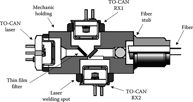
FIGURE 11.14 Section of a GPON triplexer implemented with a micro-optical mounting of discrete components.

FIGURE 11.15 Schematic layout of a GPON triplexer realized with hybrid integration technology. Filters are realized on a high index contrast chip where the location for a flip chip mounting of photodiodes, laser, and TIA is fabricated.
Voltage and current sources can be integrated into electronic chips while lasers cannot be monolithically integrated into the PLC, whose waveguides are fabricated out of suitably doped glass. This forces the adoption of hybrid integration to accommodate the laser on PLC triplexers and diplexers. Moreover, even if interesting proposals exist at the research level to built photodiodes directly into a silica substrate [27], industrial processes still require hybrid integration also for these elements. This means that the chip is no longer built only from a bare wafer using planar processes, but requires the integration of other chips [28–30]. This process increases the bill of material (BOM) weight on the cost of the component, while the BOM is inessential in the case of microelectronic chips.
11.5.1.2 GPON Interfaces Draft Cost Model
Even if the cost model of hybrid integrated GPON interfaces is not the same as microelectronics, nevertheless their cost decreases with volume, faster than the cost of micro-optics components.
In order to clarify this point in the case of GPON interfaces, let us use the same rough cost model we used for DWDM PICs in Chapter 10.
In this case, we will consider four terms in the cost of the component: Monolithic chip: This cost term decreases almost linearly with volume due to its dependence on the factory depreciation.
Bill of material: This term (i.e., the sum of all the parts that are acquired by external suppliers) decreases with a slower trend with respect to the chip cost; a reasonable approximation is to set it proportional to 1/vx, where.v.is the volume and x<1.is a parameter that is characteristic of the business area under analysis. The value of x is related to the advanatge the supplier has to have volume orders even if at lower prices. Just as an example, if we refer to the supply of a field programmable gate array (FPGA), here the production cost goes down rapidly with volume and the suppliers will push as much as possible to have volume orders. In this condition, it is clear that the price will decrease rapidly with volume and.x.will be near to one (something like 0.75, for example, the exact value depends on the particular case) If a custom micromechanical part needs to be bought, and if it is something that is manufactured only for this application, and if the volume is not really high, a lot of manual work will be involved. In this condition, a moderate increase of volume could even give no advantage in terms of price, and increasing the volume beyond a certain value could even be impossible.
In the present case, there is a mixed situation, and so to evaluate if the BOM decreases with volume, a detailed analysis is needed, a forecast for each BOM component has to be made, and then the results have to be added up, and an attempt to fit it with.a + b/vx.with.a, b, and.x.fitting parameters, and generally x<1, must be made.
Cost of work: This is the cost for workers. It decreases very slowly with volume, and only due to more efficient work that can be done in a greater structure.
Cost of structure: This is the cost of all the structures that allow products to be sold. For example, we have here research, marketing, commercials, and so on. This cost generally does not decrease with volume and sometimes it even increases.
The final result has to be multiplied for the yield, so in order to keep the model simple, we will consider a characteristic of the technology that is independent from volume. In reality, in the case of monolithic planar technology, this is not exactly true, and the yield also increases with the volume produced.
We will use this very simple model to analyze the industrial cost of four products:
A GPON B+ diplexer built in micro-optics
A GPON B+ diplexer built via hybrid integration using a high index contrast glass platform (e.g., heavily Ge-doped SiO2)
A GPON B+ diplexer monolithically integrated over the InP platform
As a reference, the GPON physical chip implementing the ranged protocol, the GEM, and so on
First of all, we fix the performances of the diplexers we have to compare, which have to be the same under a reasonable range.
TABLE 11.2 Standard Performances of GPON Commercial Interfaces
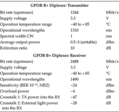
TABLE 11.3 Values of the Yields for the Various Technologies Considered in the GPON Diplexer Cost Structure Analysis
Yield (%) |
||
Micro-optics GPON diplexer |
90 |
|
Hybrid integration based diplexer |
80 |
|
Monolithic InP diplexer |
70 |
|
FPGA |
95 |
|
We will adopt the performance listed in Table 11.2.for the receiver and transmitter. These are the standard performances of commercial devices of this kind, and that fit all the standards requirements.
The values of the yields that we have used for the different production processes are reported in Table 11.3, and are typical values for new products using already available technology modules in the respective technologies.
All the other model parameters are deduced by the industrial practice, and naturally, can vary from process to process and from factory to factory, and also with regard to relevant quantities.
The results of the cost model is reported in Figure 11.16, where the industrial cost of the four products we have considered, normalized to a common constant, is plotted versus the produced volume in a year.
Since the model is quite simplified with respect to a real industrial cost evaluation, the results must be considered under the qualitative point of view more than considering the particular numerical values.

FIGURE 11.16 Cost trend with volumes produced in a year for different types of GPON diplexers and for an integrated electronic circuit (a high performance FPGA) Costs are reported in normalized units.
However, all the relevant trends emerge clearly.
Up to about 400 kpieces, the technology assuring the lower industrial cost is the micro-optics: its cost is mainly due to the cost of the BOM with a relevant contribution due to the work cost. The contribution of CAPEX depreciation is by far smaller with respect to the other technologies.
This result clearly explains why the initial phase of the GPON market was dominated by microoptics, and it has even now by far the greater part of the market.
Due to the fact that the micro-optics BOM is composed partly of integrated general purpose elements (the laser and the diode in a TCAN package, for example) and partly of more specific elements (the separation filter is an example), the BOM goes down for volumes greater than 100 kpieces, approximately at (a + b/vx), where.a.and.b.are two constants, and.x.≈ 0.65.
This trend is slower with respect to the trend relative to the hybrid technology, which has much higher costs for small volumes, but decreases faster when the volume increases.
In particular, if we consider the case of with an integrated circuit realized in heavily Ge-doped SiO2, where the laser and the photodiode are integrated with a flip chip bonder before wafer cutting, the monolithic chip would be 40% of the component cost at low volumes.
The chip cost decreases quite fast with volume, so that for volumes between 400 and 6300 kpieces, the hybrid integration technology produces the lower cost component.
Above 6 million pieces, the completely monolithic technology developed on the InP platform starts to be convenient, and from that point on, increasing the volumes it becomes more convenient.
Comparing the curve relative to the InP diplexer with the curve relative to the electronic physical protocols processor implemented with an high performance FPGA, it can be seen that the two curves are similar, due to the fact that the cost model is not so different. The curve relative to the diplexer is moved almost to the right due to the presence of a nonnegligible cost of work due to the operations of packaging and fiber coupling that have to be done chip by chip. Moreover, the fabrication of chips on a certain surface of InP costs much more than the fabrication of chips on the same area of a silicon wafer due essentially to the different cost and dimensions of the reference wafer.
The different cost trends, with volume offered by hybrid and integrated technologies, are an advantage that could be precious in the long run, when PONs volumes go up unavoidably.
On this ground, much slower that the optimistic forecasts of 10 years ago, a certain number of GPON interfaces based on hybrid integration has been launched in the market in the last few years.
This is an important event since it is the first time that integrated optics is used to reduce prices and acquire a scalable production model and not just to achieve better performances.
11.5.2 WDM-PON and XWDM-PON interface Technology
Differently from GPON, WDM-PON needs one optical interface per user not only in the ONU but also in the OLT as is shown in Figure 11.11. For this reason, optical interface technology is a key in implementing a cost-effective WDM-PON.
A trivial way of realizing a CWDM-PON is to use standard CWDM SFP transceivers. In this way, however, the cost of optical interfaces scales linearly with the number of users, being too high if a high number of users is considered. Moreover, colored ONU have to be used, thereby increasing operational costs due to the more complex management of spare parts.
Both this problems could be solved by a new class of components, called Photonic Integrated Circuits (PIC), which we have introduced for a different application in Chapter 10 [31,32].
The functional scheme of a transceiver containing a transmitting and a receiving PIC is represented in Figure 11.17,.which is functionally equal to Figure 10.1. In the transmitting PIC, a bar integrating a certain number of lasers is coupled with a PLC mux/demux (gener-ally an AWG) that launches the multiplexed channels into the output fiber. The scheme of a receiving PIC is identical, with a demux, a bar of photodiodes, and with the WDM signal incoming from the input fiber. Similarly to CWDM SFP, it seems possible to implement CWDM PIC without thermal stabilization.

FIGURE 11.17 Structure of a transceiver based on PICs.
Besides reducing the cost of OLT colored sources, PIC technology can be used also to design colorless ONUs. In this case, a PIC can be used like a tunable source, switching on only the lasers tuned on the desired wavelength.
Since PIC technology is still under development, especially CWDM PIC that the market expects to be uncooled, it is difficult to foresee exactly what the cost of one PIC for a certain production volume will be.
In any case, considering a 16 wavelength CWDM-PON, in order to have an industrial cost equal to that of a GPON, a 16 elements PIC should cost as much as the unique burst mode interface of the GPON, and this is really very difficult cost wise.
The PIC is also the approach to try to reduce interface costs in XWDM-PON. It is to underline that the first PIC prototypes were realized at 10 Gbit/s either for application in the digital optical network or simply to reduce the cost of metro equipment.
Also, in the case of WDM-PON, the adoption of PICs have to be taken into account when managing the network. The problem, as in the case of the DON, is OLT PIC failure. In this case, a set of ONUs, if not a complete WDM-PON, loses the signal.
Individual protection of PICs into the OLT is thus practically mandatory, and this also impacts on the final OLT cost.
As far as the XG-PON is concerned, the discussion is more complex. From the point of view of optical interfaces, on the ground of standard requirements, there are not so many choices from among the state of the art.
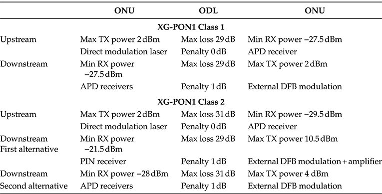
The characteristics of the transmitter and receiver are summarized in Table 11.4.for class 1 XG-PON1 (28 dB power budget) and class 2 XG-PON1 (31 dB power span)
These optoelectronics components can be mounted onto a package using micro-optics methods and they can also be assembled in a hybrid or monolithic chip. In any of these cases, all the considerations already done for the GPON still hold with the further issue that the circuit to convey the electrical signal to the modulator at 10 Gbit/s is much more complex with respect to that working at 2.5 Gbit/s, thereby further increasing the cost of the OLT optical module package.
TABLE 11.4 Possible Optical Interfaces for the Two Classes of XG-PON1:Class 1 Table and Class 2 Table
Besides these elements that are almost all in common with the GPON case, in the case of the XG-PON1, another difficulty arises, that is not present in the GPON.
Due to the broadcast nature of the ODN and the continuous change of frame slot allocation among the ONUs because of the DBA, the signal arriving at the ONU is a burst signal and it needs a burst mode receiver. Every ONU receiver must be able to detect the arrival of a burst and to rapidly lock the sampler at the burst, so as to sample the signal at the right point of the bit interval.
While at 2.5 Gbit/s, a burst mode receiver is difficult to implement, at 10 Gbit/s it is a real technology challenge. The first experimental components were presented in the year 2009 (e.g., [33]), but more developments will be needed to achieve the desired performance and cost targets imposed by the application.
REFERENCES
1.. A. Leshem, The capacity of next limited multichannel DSL, Sensor Array and Multichannel Signal Processing Workshop Proceedings, Barcelona, Spain, pp. 696–700, July, 18–21,, 2004.
2.. Annual fiber deployment, Fiber Optics Weekly Update, September, 17, 2008, http://findarticles.com/p/articles/mi_m0NVN/is_11_23/ai_99013219 (accessed: November 24, 2010)
3.. H. A Hmida, G C Cordner, A Amer, F F. Shalan, FTTH design and deployment guidelines for civil work, fiber distribution and numbering, Optical Fiber Communication Conference, 2006 and the 2006 National Fiber Optic Engineers Conference, OFC 2006, Anaheim, CA, 10.pp,March 5–10, 2006.
4.. A Badoz,, .Sustainable competition through fibre deployment, Convergence Think Tank Seminar BERR–Department for Business Enterprise & Regulatory Reform, London, U K., April.22, 2008.
5.. ITU-T Recommendations defining the GPON standard
G 984.1: General characteristics for GPON 1/2003 G 984.2 GPON: PMD layer specification 1/2003 G 984.3 GPON: TC layer specification 10/2003 G 984.4 GPON: ONT Management and Control Interface spec. 5/2003
6.. G Kaiser, FTTX Concepts and Applications, John Wiley & Sons, Hoboken, NJ, 2006, ISBN:9780471704201.
7.. F Chang, Understanding 1G EPON power budgets in IEEE formalism, IEEE 802.3 Plenary Meeting, San Francisco, CA, July.2007.
8.. H Kim, , F Bien, J. de Ginestous, S. Chandramouli, C. Scholz, E. Gebara, .J, Laskar, Electrical dispersion compensator for a giga-bit passive optical network system with Fabry-Perot laser, Microwave Symposium, 2007, Honolulu, HI, IEEE/MTT-S International, pp. 207–210, June.3–8, 2007.
9.. W W. Peterson, E J. Weldon,. Error-Correcting Codes—Revised, 2nd edn.,MIT Press, Cambridge, MA,.1972, ISBN 0262130390.
10.. R. B. Ellis, F. Weiss, O.M. Anton, HFC and PON-FTTH networks using higher SBS threshold singlemode optical fibre, Electronics Letters, 43(7), 405–407 (2007)
11.. C. F Lam(Ed.), Passive Optical Networks: Principles and Practice, Academic Press, San Diego, CA, 2007, ISBN-13: 978-0123738530.
12.. B. Skubic, J. Chen, J., Ahmed, J. Wosinska, L.Mukherjee, B. A comparison of dynamic bandwidth allocation for EPON, GPON, and next-generation TDM PON, IEEE Communications Magazine, 47(3), S40–S48.(2009)
O. Haran, A .Sheffer, .The importance of dynamic bandwidth allocation in GPON networks, Sierra White Paper, 2008, www.Sierra.com (accessed: November 29, 2010).
14.. M. Burzio, Next generation access network: Tecnologie ed Apparati (in Italian), IST Workshop, 2008, http://ist-sms.org/upl/File/Presentazione%20Burzio.pdf (accessed: November 29, 2010).
15.. M. De Bortoli, M. Mercinelli, P. Solina, A. Tofanelli, Access optical technologies, passive optical networks, Telecom Italia Technical Review (in Italian), 13(1),104–119, http://net infocom uniroma1 it/corsi/Infrarete/materiale/PON%20Telecom%20Italia pdf (accessed: November 29, 2010)
16.. R. Bond, ITU PON—Past, present, and future (Telcordia Representative), FTTH Council Webinar, July.30, 2008
17.. C J. Chang-Hasnain, Optically-injection locked tunable multimode VCSEL for WDM passive optical networks, Nano-Optoelectronics Workshop, Tokyo Japan, pp. 98–99, 2008.
18.. H C .Lu, W.-S Wang , Cyclic arrayed waveguide grating devices with flat-top passband and uniform spectral response, IEEE Photonics Technology Letters, 20(1), 3–5 (January.1, 2008).
19.. F J. Effenberger, XG-PON Tutorial, .IEEE Optical Fiber Communication Conference, OFC 2010, San Diego, CA, Paper OWX4, 2010.
20.. S.-J. Park, C.-H. Lee, K.-T. Jeong, H.-J Park, J.-G..Ahn, K.-H.Song, Fiber-to-the-home services based on wavelength-division-multiplexing passive optical network, IEEE Journal of Lightwave Technology, 22(11), 2582–2591.(2004).
21. C. Berthier, G. Wecker.FTTH Deployment Cost, SOGETREL’s experience, Digiworld Summit 2006, Montpellier, France, November.14, 2006.
22.. E. Iannone, FTTH: Enabling technologies and deployments, ECOC 2007 Market Forum, Berlin, Germany, September.16–20, 2007.
23.. W.-P. Huang, X. Li, C.Q Xu, C.Hong, W. Liang, Optical transceivers for fiber to the premises applications: System requirements and enabling technologies, .IEEE Journal of Lightwave Technology, 25(1), 11–27.(2007).
24.. Y.-L. Cheng , Y.-H. Lin, M.-C. chang, F.-Y. wang, C.-S. Wu, Y.-C .Yu, Integrated a hybrid CATV/GPON transport system based on 1.31/1.49/1.55./spl mu/m WDM transceiver module, Quantum Electronics and Laser Science Conference, QELS, 3, 1678–1680.(2005).
25. L. Xu, H. K. Tsang, Colorless WDM-PON optical network unit (ONU) based on integrated nonreciprocal optical phase modulator and optical loop mirror, IEEE Photonics Technology Letters, 20(10), 863–865(May 15, 2008).
26.. A. Behfar, M. Green, A. Morrow, C. Stagarescu Monolithically integrated diplexer chip for PON applications, Optical Fiber Communication Conference, 2005, OFC/NFOEC, Anaheim, CA, Vol.2, p.3, March.6–11, 2005.
27.. G. Wohl, C. Parry, E. Kasper, M. Jutzi, M. Berroth, SiGe pin-photodetectors integrated on silicon substrates for optical fiber links, IEEE International Solid-State Circuits Conference, 2003, ISSCC, San Francisco, CA, Vol1, pp374–375, 2003.
28. A R. Mickelson, Basavanhally, N. R., Lee, Y.-C., Optoelectronic Packaging, Wiley Interscience, New York, 1997, ISBN: 0471111880.
29. G. E Henein, D J. Muehlner, J. Shmulovich, L. Gomez, M A Capuzzo, E J. Laskowski, R. Yang, J V. Gates, Hybrid integration for low-cost OE packaging and PLC transceiver, Lasers and Electro-Optics Society Annual Meeting, 1997, LEOS ‘97 10th Annual Meeting, Conference Proceedings, IEEE, San Francisco, CA, Vol.2, pp.297–298, November.10–13, 1997.
30. S.-J. Park, K.-T. Jeong, S.-H. Park, H.-K. Sung, A novel method for fabrication of a PLC platform for hybrid integration of an optical module by passive alignment, IEEE Photonics Technology Letters, 14(4), 486–488.(2002).
31.. S.H. Oh, Y.-J. Park, S.-B. Kim, S. Park, H.-K. Sung, Y.-S. Baek, K.-R. Oh, Multiwavelength lasers for WDM-PON optical line terminal source by silica planar lightwave circuit hybrid integration, IEEE Photonics Technology Letters, 19(20),1622–1624.(2007).
32.. D.J.H. Lambert, C.H. Joyner, J. Rossi, F A. Kish, R. Nagarajan, S Grubb, F. Van Leeuwan, M. Kato, et al, Large-scale photonic integrated circuits used for ultra long haul transmission, The 20th Annual Meeting of the IEEE Lasers and Electro-Optics Society, LEOS 2007, Lake Buena Vista, FL, pp. 778–77, 2007.
33.. Y. Chang, (Frank), First demonstration of a fast response/locking burst-mode physical layerchipset for emerging 10G PON standards, European Conference on Optical Communications— ECOC 2009, Vienna, Austria, p. 629, 2009.