
08
BIM Collaboration and Working within the Common Data Environment
Introduction
While the focus of the Government BIM Strategy has been on formal ‘data drops’ for gateway reviews and asset information, there is an ongoing need for project team members to improve their collaboration by regularly sharing informal ‘work in progress’ information with each other. This chapter highlights the importance to team collaboration of using BIM effectively in the Common Data Environment.
The key coverage in this chapter is as follows:
- The risks of information model sharing in the CDE
- Open BIM workflows
- Value and design fixity in BIM
- Capturing design options in BIM
- Automatic design verification in BIM.
The Risks of Information Model Sharing in the CDE
The Common Data Environment (CDE) was described in Chapter 2 as ‘a single source of information for any given project, used to collect, manage and disseminate all relevant approved project documents for multi-disciplinary teams in a managed process’. Given that the multi-disciplinary team may be geographically dispersed, it makes sense for this requirement to be fulfilled by an online data repository.
The diagram below indicates the four major categories of information exchanged through the CDE: Work in Progress, Shared, Published Documentation (as approved by the client) and Archive (the last is ultimately verified to be ‘as-built’ at hand-over).
The Common Data Environment should be able to provide the following:
- Authentication of all personnel who use the system and are designated to exchange information through it on behalf of their respective project team members.
- A consistently applied file naming convention capable of adequately distinguishing all revisions to the model files, drawings and data extracted from them.
- Form-based user interface for assigning properties that indicate the purpose for which each model is being issued.
- An ‘audit trail’ of the file exchange sequence that indicates the progression of model development throughout the design and construction process.
- Verification of which revision of each model is to be used in conjunction with others.
- Assurance that project members are working with the most recently approved versions of each other’s models and issued data.
Design data is typically shared among project team members far more regularly than it is issued to the client for approval. The purpose of the Shared section of the Common Data Environment is to ensure that multi-disciplinary design proposals and model changes are continuously collected and correctly disseminated with recipients notified.
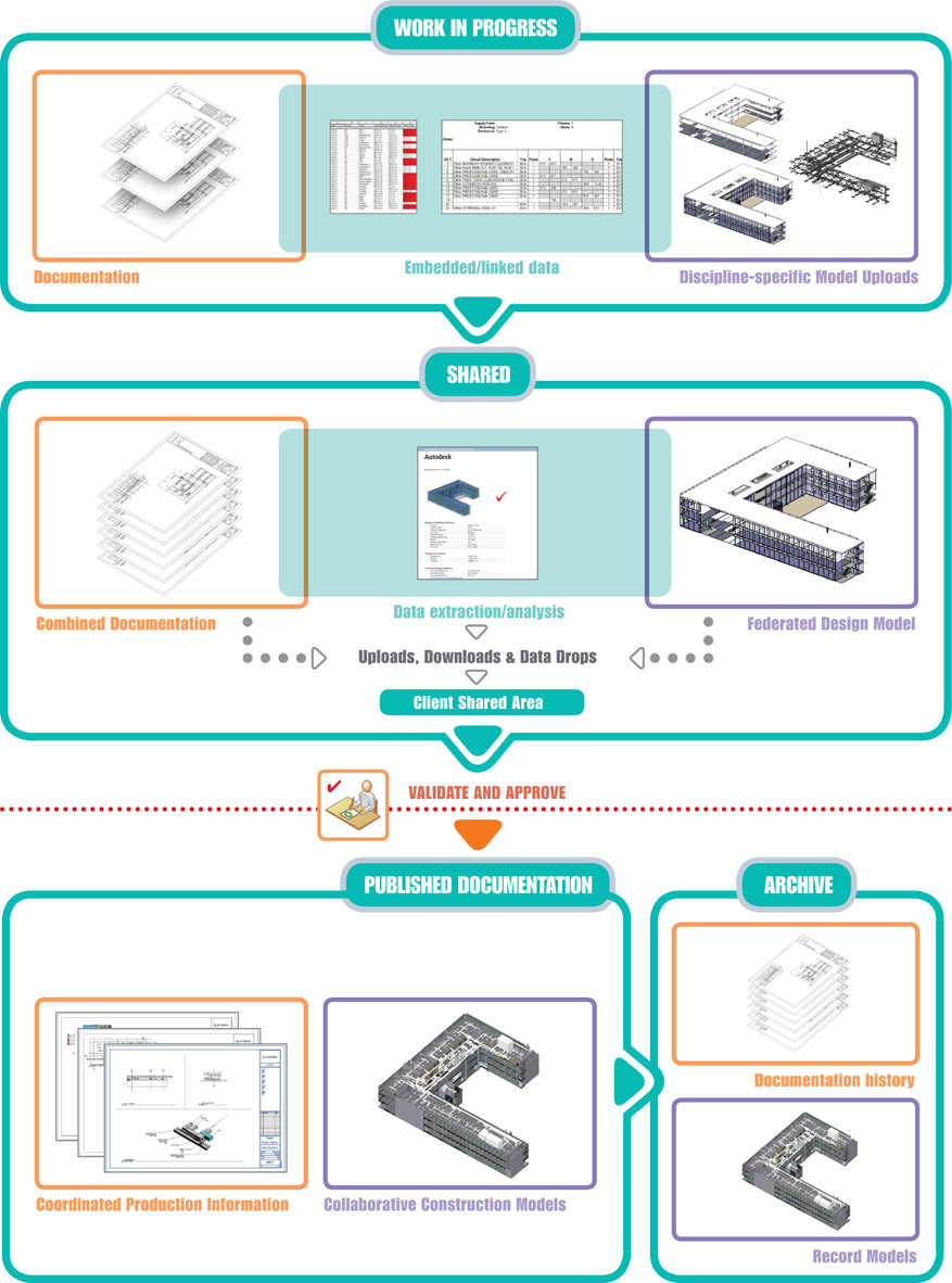
Figure 8.1 The Common Data Environment

Figure 8.2 Informal information exchanges - Work-in-progress (WIP) is verified by each discipline and uploaded for coordination through the Common Data Environment
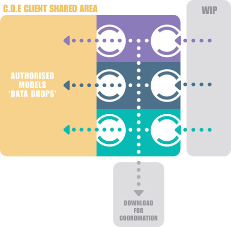
Figure 8.3
Formal ‘data drops’ as agreed in BEP, Lead Designer/Main Contractor coordinate and verify project models and data before scheduled submission for approval through the Client Shared Area of the Common Data Environment
Despite best intentions, the relative ease and informality of these information exchanges can lead to complacency. Whereas drawing changes will be clearly identified through revision clouds and notes, the annotation of significant revisions to shared models is not nearly as commonplace.
Applying change control to the model is important because the model is the chief means of communicating definitive design consensus in BIM Level 2. The CIC BIM Protocol establishes that in cases of discrepancies between the model and information extracted from it (such as drawings and schedules), the model should normally take precedence.
Open BIM Workflows
When the model is shared through the CDE with the aim of achieving consensus collaboratively, there is often a need to initiate a discussion about a specific design issue or problem and associate it with specific elements stored in the model.
The exchange of BIM data in proprietary formats that are incompatible with each other can actually hinder the fluidity of communication between project participants. As a means of overcoming this incompatibility, there is an industry-wide non-proprietary data structure for defining 3D BIM objects, called Industry Foundation Classes (IFC). Its ongoing development was the responsibility of the former Industry Alliance for Interoperability (IAI), which when it was founded in 1994 as a consortium comprising the largest CAD software vendors and a number of major US building industry firms. Over the next two decades, the IAI expanded globally into what is now known as buildingSMART International.
Alongside IFC development, the BIM Collaboration Format (BCF) evolved as an additional non-proprietary, open data standard for communicating design and construction issues via the 3D model. Although it was introduced by Solibri, Inc. and Tekla Corporation in 2009, there are now a range of BCF applications that are add-ons to most industry-leading BIM design creation programs.
As shown in fig.8.5 below, the BCF issue file includes a description of the issue itself, links to the specific BIM elements involved, and the key model view in which recipients can locate the issue.
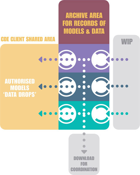
Figure 8.4
Maintaining project history: At key milestones, project models and data are transferred to the Archive Area in the Common Data Environment
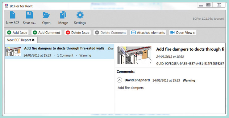
Figure 8.5
BCFier: a BIM software extension for model-based issue capture1
To highlight an issue in the model using BCF, the user selects one or more elements in a 3D view and clicks on the ‘Add Issue’ button. The resulting dialog box will launch the PC’s standard picture editor for marking up a small image capture of the chosen model view. Furthermore, several of these issues can be captured and compressed into a single BCF file (*.bcfzip) which can be distributed via the Common Data Environment to other members of the project team for comment.
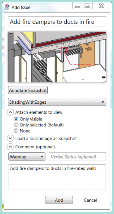
Figure 8.6
Adding an issue in BCF
The recipient opens the issued model and compressed BCF Report file. Clicking on any of the listed items will not only display the marked up image, but also open the model in the intended model view and select the associated model elements.
Creating a ‘Read-Only’ Model Snapshot
As shown below, the BIM Collaboration File correlates each issue to its associated model elements by means of the global unique IDs (GuIDs) that distinguish every object exported to IFC.
Given the possibility that the authored model might inadvertently be updated by the recipient, it is often better to export the static IFC model that relates specifically to the issues identified in the BIM Collaboration File. There are several software applications for opening and walking through IFC files in 3D, including Solibri Model Checker®, Tekla BIMSight® and Autodesk Navisworks®. A range of add-on applications have been developed for these tools, enabling users to review issues recorded in the BIM Collaboration File in conjunction with the IFC model.
Assigning and Notifying of Model Status

Figure 8.7
List of IFC elements correlated to a particular BCF issue
Those involved in developing the BIM Project Execution Plan for a given project should prioritise the implementation of form-based mechanisms for classifying and notifying recipients of the overall purpose for which different model revisions were intended. This and other descriptive information about each model are known as meta data.
PAS-1192 provides a list of abbreviations, called status codes, that should be used as meta data to signify the purpose and quality of issued information.
Review only Model Revisions
Often, work-in-progress models are issued as an exploration of a design concept, and for review only, rather than for definitive design coordination. As described in Chapter 3, model revision file naming would be expected to adhere to an industry-standard convention, such as BS-1192. In accordance with the latter, before issuing ‘review only’ revisions, file name suffixes should be changed from P01, P02 to R01, R02, etc.

Figure 8.8
Status Codes in the CDE (PAS-1192-2)2
On receipt, the file should be downloaded to a date-stamped sub-folder on the recipient firm’s server where the project’s incoming files are stored. The file should not be opened directly, as it is a record of the issued model. Instead, it should be copied into an appropriate review folder and opened as a standalone file. While any links to other models must be reloaded, under no circumstances should the previously accepted model revision be overwritten until a new formal P revision is issued.
Value and Design Fixity in BIM
Design fixity is attained through what is known as ‘Last Responsible Moment’ (LRM) decision-making. The LRM is that team review decision-point beyond which the cost of delay outweighs the benefit of delay.
Fixity is attained on a design issue relating to specific elements when there is sufficient consensus among key decision–makers for the project to progress. It is not the same as ‘design freeze’, since the latter establishes constraints on the scope of further design development. Nevertheless, fixity does provide an agreed basis for making and communicating decisions.
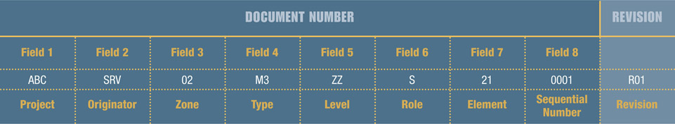
Figure 8.9
Review document numbering example3
The ‘Last Responsible Moment’ for any issue is a decision for the Project Manager to make, but it will be informed by several factors, including the required lead-time for developing and issuing documentation. Since awaiting further expert input indefinitely is not a viable option, the design team must commit to a decision at that LRM or begin to lose money.
In these situations, the model is ideal for quickly disseminating the team’s consensus on design issues across the entire project. The publishing of an interim federated model (with fully annotated changes) to all project members will ensure that each discipline promptly institutes coordinated changes in respect of any aspect of design fixity that affects them.
For example, consider the design and procurement process for a specific construction work package, such as groundwater and drainage. The design would need to undergo specialist technical and cost review before it is formally issued to the main contractor. Although the team might want to postpone issuing the design to ensure that it fully incorporates belated specialist input from the appointed subcontractor, further delay might compromise the overall project deadline and incur severe penalties. At that point, it would be better to issue coordinated data that represents the design team’s consensus on the best information to date, so that the contractor can maintain progress on the project. That data would be issued provisionally on the understanding that it still requires a measure of revision in the light of future discussions with the specialist subcontractor.
Since for BIM Level 2 the exchange of the model is the chief means of communicating design intent holistically, the above revisioning regime is applicable to entire models representing each discipline or specialism. On the more granular scale of specific groups elements, it is important to record within each model any changes that represent this level of consensus.
One useful mechanism for recording consensus within the model is the BIM Coordination File, which was described earlier in this chapter. The issue of these federated coordination models is in addition to the regular exchange of single-discipline models.
Delays in propagating design fixity into the model are probably the most significant hindrance to BIM adding value. Until a design consensus is reflected in the model, the model (which, under the CIC BIM Protocol, takes precedence over information extracted from it) ceases to communicate the entire agreed status of the design. The whole point of BIM is to ensure that project consensus resides in the centrally accessible model, instead of remaining in the traditionally separated and unconnected silos of information retained by each discipline.
Capturing Design Options in BIM
The impact of design alternatives must be thoroughly reviewed before the project team can arrive at a consensus. There are two key aspects to accomplishing this through a BIM workflow.
- Revision management
- Development of design options in the model.
Revision Management
In fig.8.10 on the facing page, the Architectural Model P01 (in purple) precedes all other disciplines and is placed in the Common Data Environment along with associated drawings and documentation.
This file is downloaded by recipients and linked into the first structural (green) and MEP (yellow) models.
Interim models are issued by each discipline as snapshots of design alternatives or to demonstrate the current state to which the design has progressed. Interim models should use the R01, R02 suffixes as these are for review only.
The issue of structural revision P02 does not precipitate the sharing of immediate corresponding revisions for MEP and Architecture.
All models will undergo work-in-progress versioning to capture changes that represent a milestone or internal design consensus (these marked in grey, these are marked, e.g., P01_1, P01_2, etc.). Introducing another discipline’s updated model should also prompt a new version of the main model that includes these updates.
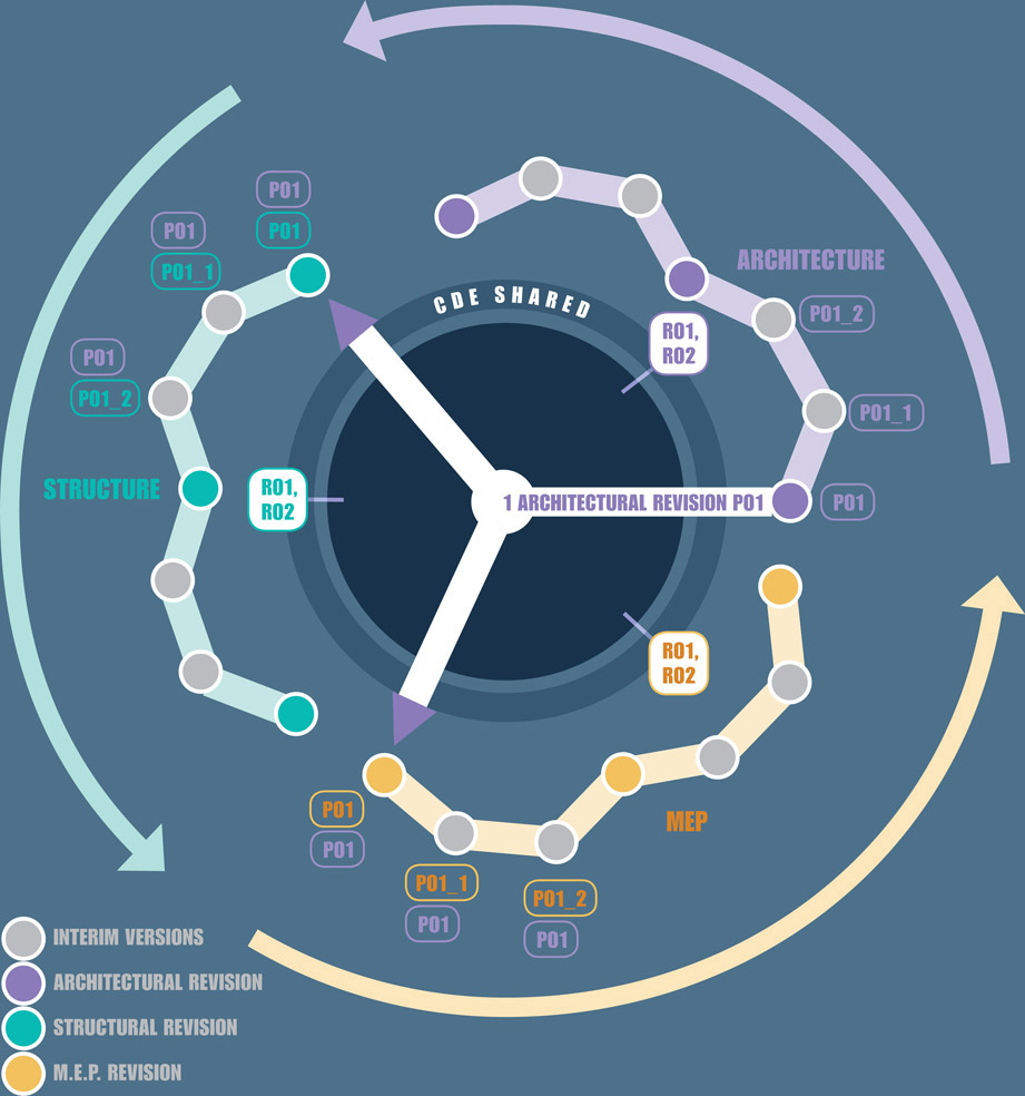
Figure 8.10 Sharing of first architectural revision, P01
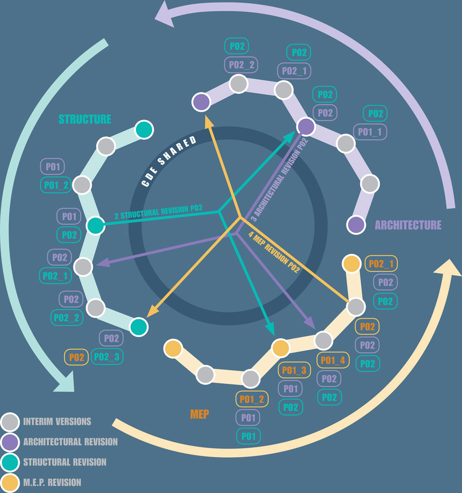
Figure 8.11 Internal versioning of models after linking to structural and MEP revisions, P02
As shown on the facing page (fig 8.11) the MEP model has been simply iterated to the next versions (P01_3, P01_4) until the coordination schedule, a design deadline or the achievement of team consensus prompts the engineers to release their next revision, P02. This model is incorporated into the architectural and structural workstreams by versioning their models with the suffix P02_3.
Development of Design Options in the Model
Model development workflows can incorporate design options. Once created, each option can be isolated in corresponding views and schedules. In the Autodesk Revit® example below, the cruciform pitched roof is the primary option.![]()

Figure 8.12
Primary design option – Cruciform roof4

Figure 8.13
Secondary design option – Cruciform barrel roof4
![]() A cruciform barrel roof has been added to the second design option. The view is duplicated and modified to isolate the barrel roof.
A cruciform barrel roof has been added to the second design option. The view is duplicated and modified to isolate the barrel roof.
The wall below that is coordinated with the primary option is noticeably uncoordinated with the second:

Figure 8.14
Secondary design option – barrel roof coordinated with walls4
![]() The resolution of this issue requires any connected elements to be duplicated and added to both design options:
The resolution of this issue requires any connected elements to be duplicated and added to both design options:

Figure 8.15 Secondary design option – barrel roof coordinated with walls4
![]() Sets of walls belonging to each option can now be joined to their corresponding roofs
Sets of walls belonging to each option can now be joined to their corresponding roofs
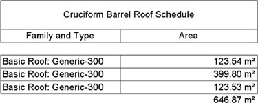
Figure 8.16
Roofing schedule for primary design option4
![]() The associated schedule can also be set to display data associated with a particular option
The associated schedule can also be set to display data associated with a particular option

Figure 8.17
Roofing schedule for secondary design option
![]() Any option can be set to be primary and the primary option can be accepted (once a consensus has been reached), at which stage any other options within that option set will be deleted.
Any option can be set to be primary and the primary option can be accepted (once a consensus has been reached), at which stage any other options within that option set will be deleted.
Automatic Design Verification in BIM
The ability to apply automatic rule checking to models is one of the most important developments in BIM software. It heralds a future in which clients will be able to use ‘self-service’ web-based tools to verify that design work complies with codes and other specified approval criteria.
Rules can be used to check on model integrity, e.g. whether there are duplicate elements that would produce erroneous schedules, or whether all partition types have been updated to those agreed in construction procurement.
Alternatively, the rules can produce a complete inventory of proposed furniture, fixtures and equipment for the intended building.
Industry-recognised tools like Solibri Model Checker® allow users to combine several rules into a ruleset that can be run on an IFC file.
As an example, one of the accessibility requirements rules checks doors in conjunction with associated spaces in the following ways:
| Free Door Front Side | This requirement checks on the unobstructed minimum area in front of the door. |
| Free Door Back Side | This requirement checks on the unobstructed minimum area behind the door. |
| Free Door Side | This requirement checks on the unobstructed minimum area in front of a swing door, on the side opposite to hinges. |
| A + B > 2300 | This special requirement checks on the overall width and depth of unobstructed minimum area in front of the door |
Figure 8.18 Ruleset folders: Solibri Model Checker®5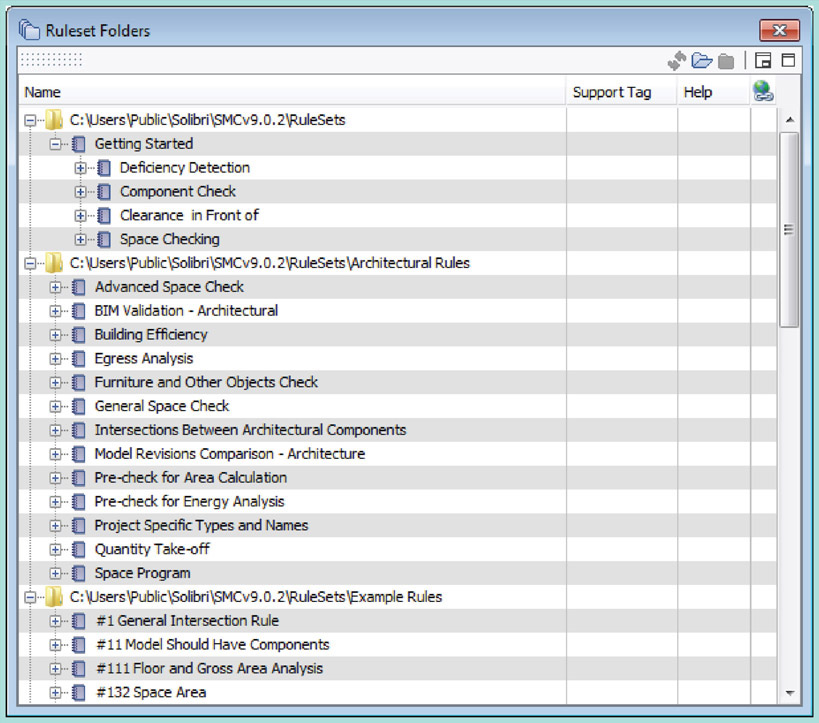
There are also pre-defined rules that can check on ramp and stair accessibility, verify that elements are connected to the defined spaces that enclose them and that perform automatic escape routes analysis.

Figure 8.19
Accessibility requirements ruleset dialogue box – Solibri Model Checker®5

Figure 8.20
Escape route analysis – Solibri Model Checker®5
Conclusion
The major efficiency improvements promised by BIM will only be realised to the extent that entire project teams adopt the ‘best practices’ of model-based collaboration. As discussed, there is a wide range of tools and methods available for tracking design and construction issues in the model, for iterating revisions precisely, developing design alternatives and processing models for code and other design criteria compliance.
In order to automate design verification in BIM, it is crucial that models are developed carefully, vetted before issue and then exchanged in accordance with agreed protocol. Adequate time for this must be factored into the design process.
It is likely that it is only a matter of a few years before it becomes commonplace for clients to run code and design criteria checks on uploaded IFC models through a self-service web portal. The advent of this innovation would transform into a reality this aim that is central to the achievement of BIM Level 3.