
09
Level of Definition Progression in BIM

Introduction
Collaboration is only successful when the scope of each participant’s contribution is clearly defined. Before BIM, level of detail was the main gauge of responsibility for developing more specific design intentions in the project drawings and associated data.
For BIM Level 2, the Level of Definition (LOD) extends level of detail to include the quality of information that is either embedded in or linked to different categories of elements in the federated model.
For agreed purposes at each work stage, the LOD should:
- Establish the extent to which, for specified purposes, each project member is contractually obliged to develop elements of the model and embed or link different aspects of design, construction and facilities management information to it.
- Gauge the extent to which elements from each model and their associated data should be relied upon by other members of the project team.
In this chapter, the Model Production and Delivery Table (MPDT) will be explained as a management tool for assigning responsibility to different project members for adding increasingly definitive information and geometric detail to various elements in the 3D model.
3D coordination will also be considered, as it is particularly affected by LOD. This is because those involved in this process must make allowances for the tentative size and positioning of various building components, until they are understood to be definitive.
The key coverage of this chapter is as follows:
- The importance of design sequence to Levels of Definition
- Classifying Levels of Definition
- How LOD affects coordination
- Modelling access and clearances in 3D.
The Importance of Design Sequence to Levels of Definition
When a particular level of definition is designated for different types of models and elements, it becomes the basis for interpreting the degree of design intent that they convey, whether conceptual, fully specified, or the final ‘as-constructed’ representation.
Level of Definition is an estimation that comprises two gauges of design development: the level of detail and the level of information. Whereas level of detail is primarily related to the geometric presentation of model elements, level of information refers to any text and numerical data correlated to those elements.
During the collaborative process, consensus will be achieved for some features of the design significantly earlier than for others. For instance, the structural shop drawings might be ready long before the building services have been detailed for fabrication. It is due to the interdependence of these various systems that the specification is required indicating how LOD should progress over the course of the project.
As another example: as long as ceiling heights are still no more than architectural approximations, heating and cooling loads – which are based on room volumes – cannot be calculated accurately. Similarly, the structural engineer will be unable to calculate the loading on the plant room floor with precision until the services engineer has specified a particular model of air handling unit.
Therefore, LOD measures how specifically both the geometry and information issued via one party’s models and elements can and should be relied upon by other project participants in the design and construction process.
Classifying Levels of Definition
The numerical values for LOD classify the progression of different categories of elements from tentative to definitive over the course of the project:
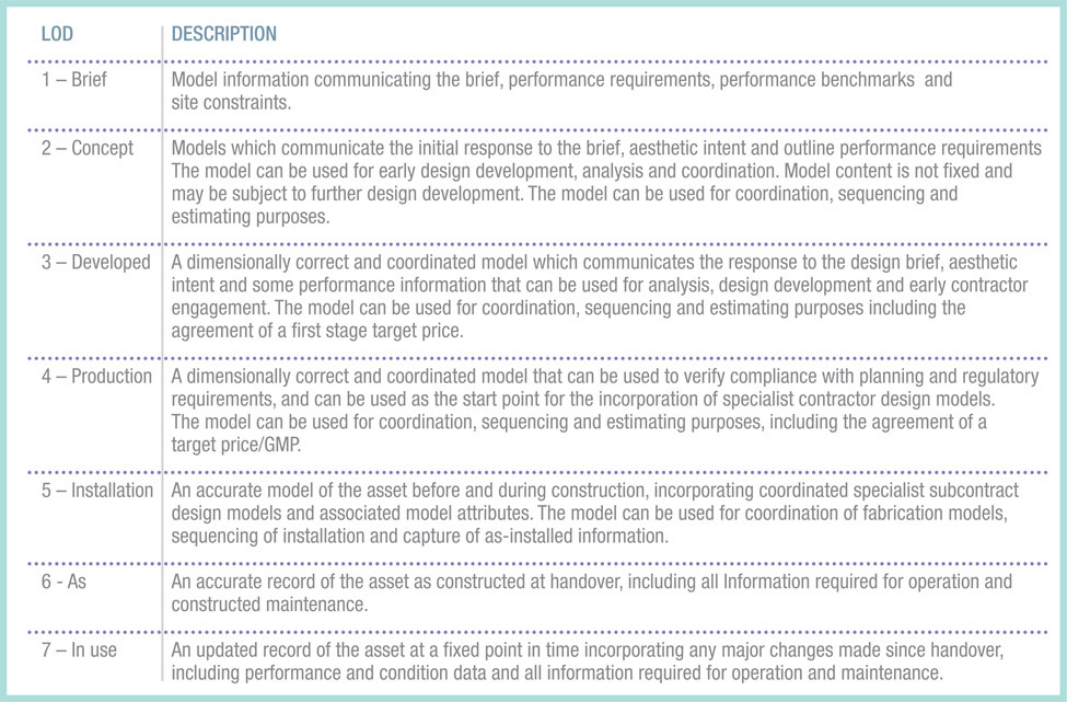
Consider the previous example of a building services engineer calculating heating and cooling loads. From the outset of the project, it might have been agreed that, by RIBA stage 3, the ceilings in the architect’s model would be at LOD 2. On that basis, the lack of definitive ceiling levels would make the engineer’s room volume calculations tentative. As a result, the consequent sizing of air conditioning equipment would be treated as approximate. Level of Definition seeks to generate this kind of common understanding about information exchanged between members of the project team.
LOD also establishes the completeness of the model elements and data required for formal issue to the employer at each gateway decision-point. This is why the Model Production and Delivery Table (below) that specifies LOD for the entire project is structured by ‘data drops.’
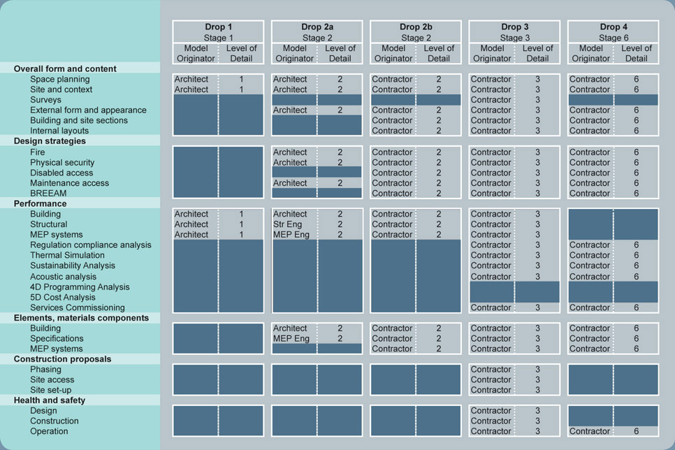
Figure 9.1
Model Production and Delivery Table (CIC BIM Protocol, Appendix 1)2
The BIM Toolkit®: Level of Detail and Level of Information
A progression from the tabulation of model development responsibilities, the BIM Toolkit® is an online management tool that facilitates project data exchange via BIM to the level of definition required for each work stage. Standards for Level of Detail (LoD) and Level of Information (LoI) have been published as part of the BIM Toolkit, aligned to the RIBA/CIC/PAS1192 work stages.
It is intended that these, along with Uniclass 2015 naming conventions, should be adopted as part of the UK Level 2 suite of BIM documents which form a cohesive suite of documentation required for UK Level 2 BIM adoption. The Toolkit assists in both the understanding of these definitions and classification structures and their application on projects across some 9000 building elements.
The Toolkit currently provides over 400 examples of LoD and LoI representations for Architecture, Infrastructure, Landscape Architecture, Civil, Structural and MEP elements across all appropriate work stages. These also provide useful links to the National BIM Library, allowing more direct access to relevant BIM content.
By separating the graphical and geometric definition of BIM Systems and Objects (LoD) from the data attached to these objects (LoI), the Toolkit verifies uploaded BIM data against defined standards of modelling and data completeness. This capability supports several areas of design progression.
As outlined in Chapter 4, the Toolkit provides a suite of project management tools to support the development of a Design Responsibility Matrix. The application of LoD standards means that, from the outset of each work stage, each project participant is aware of the expected geometric definition to be provided for the model elements under their ownership. Consistency in the geometric content of model contributions from all disciplines allows a more rigorous approach to design coordination and clash detection to be used. By consistently applying the Toolkit’s LoD, all disciplines will be providing equivalent standards of information. Equally, applying LoD standards to project data generated for all RIBA/CIC/PAS1192 work stages ensures that more uniform geometric and graphical output will be achieved.
The separation of LoD and LoI offers further benefits for model development and information management. By separately defining LoI, the Toolkit effectively confirms the necessary briefing information at an elemental level at the commencement of each work stage. Initially, this will simply confirm requirements against spaces or rooms, which, in later work stages, then informs the development of Systems and Objects that enclose the spaces, e.g. walls, doors, slabs, systems serving spaces etc.
https://toolkit.thenbs.com
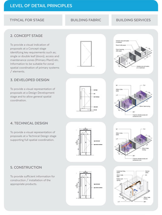
Figure 9.2 Level of Detail Principles 23
At the end of each work stage, Information Exchanges must then provide the necessary responses to the briefing questions that were asked at the beginning of that stage. The Toolkit assists in a number of areas by providing
- The framework through which LoI is defined.
- Guidance on what information is required at an elemental level for each work stage.
- Checking tools to confirm model outputs against defined deliverables by work stage.
- Ultimately, links to the NBS Create product to assist with more automated specification production.
How LOD affects Coordination
LOD can have a real bearing on the ability to resolve coordination issues in BIM and it must be taken into account when checking for clashes or clearances.
For example, at RIBA Stage 2, the model might contain two boilers separated by a clearance of 3 metres. Despite their detailed geometry, the boiler elements should only be interpreted as indicative in specification, location and size at LOD 2.
At Stage 2, if the model was used to review facility management issues, the prospective building manager might highlight access and maintenance issues associated with the 3m clearance between the boilers. At that point in the project, it would be explained that equipment sizes and locations remained tentative, but that the concerns expressed would be recorded as an issue for future resolution (using the BIM coordination file mentioned in Chapter 8).
By RIBA Stage 4, the dimensions of the boilers and distance between them should be resolved since elements at the corresponding LOD 3 can be used to finalise coordination for installation, access and maintenance.
Modelling Access and Clearances in 3D
The required access and clearances should be modelled in addition to 3D geometry of any equipment itself. As an example, the 3D boiler shown on the facing page is derived from the NBS National BIM Library. It has been modelled with a volume that represents its clearance zone.
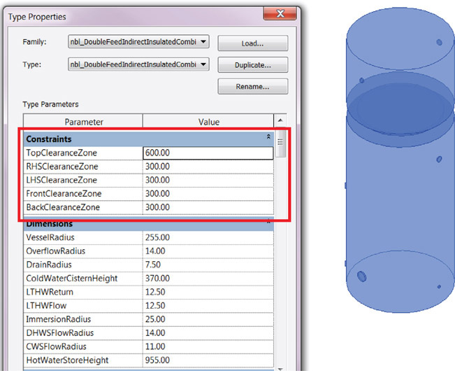
Figure 9.3
Clearance zone dimensions as boiler modelling parameters4
The modelled clearance zone can be switched on and tested for interference with other components in the designated 3D coordination review software.
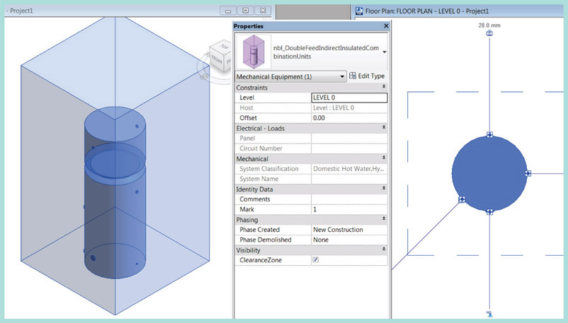
Figure 9.4
Modelled clearance zones in 3D and plan4

Figure 9.5
Interference between clearance zones detected in the model4
Conclusion
The level of definition described in PAS-1192 gauges the extent to which elements from each model and their associated data should be relied upon for re-use by other members of the project team. As such, it is primarily aimed at establishing progressive project-wide expectations for using the model.
As an appendix to the BIM Protocol, the Model Production and Delivery Table (MPDT) provides a means of specifying who is responsible during each work stage for the design and required level of definition for the entire range of BIM deliverables. Therefore, it is important for this table to reflect a realistic apportionment of responsibility for progressing model development throughout the project, from the conceptual to the ‘as-built’ representation of the building.
As a part of the protocol, the MPDT should be reviewed carefully and critically by each firm’s BIM Manager. For later project stages, model elements must be re-examined all the more closely to ensure that they represent the agreed level of definition upon which other project team members will rely.
By providing a portal that verifies BIM data against defined standards of modelling and information completeness at each project stage, the BIM Toolkit™ represents a significant advancement on tabular methods of controlling levels of definition.
By adding to each piece of equipment in the model the 3D clearance zones that represent its respective required access and maintenance space, 3D coordination is improved.
In the last chapter, we will explore how to aggregate and hand over the data embedded in the model that will allow the self-same equipment to be maintained.