Tool-based risk assessment of cloud infrastructures as socio-technical systems
Michael Nidda; Marieta Georgieva Ivanovab; Christian W. Probstb; Axel Tannera a IBM Research, Zürich, Switzerland
b Technical University of Denmark, Kongens Lyngby, Denmark
Abstract
Assessing risk in cloud infrastructures is difficult. Typical cloud infrastructures contain potentially thousands of nodes that are highly interconnected and dynamic. Another important component is the set of human actors who get access to data and computing infrastructure. The cloud infrastructure therefore constitutes a socio-technical system. Attacks on socio-technical systems are still mostly identified through expert brainstorming. However, formal risk assessment for systems including human actors requires modeling human behavior, which is difficult at best. In this chapter, we present a modeling exercise for cloud infrastructures using the socio-technical model developed in the TRESPASS project; after showing how to model typical components of a cloud infrastructure, we show how attacks are identified on this model and discuss their connection to risk assessment. The technical part of the model is extracted automatically from the configuration of the cloud infrastructure, which is especially important for systems so dynamic and complex.
Acknowledgments
Part of the research leading to these results has received funding from the European Union Seventh Framework Programme (FP7/2007-2013) under grant agreement no. 318003 (TRESPASS). This publication reflects only the authors’ views and the Union is not liable for any use that may be made of the information contained herein.
1 Introduction
Assessing risk in cloud infrastructures is difficult. While a singular node is not so difficult to configure and analyze, a typical cloud infrastructure contains potentially thousands of nodes that are highly interconnected and dynamic. Studies by ENISA (2009) as well as CSA (2010) highlight the risks and threats in such environments.
In this chapter, we present a modeling exercise of a process developed in the TRESPASS project. The model captures details of cloud infrastructures at several levels—from the overall structure over network communications to services running on a single node—and can represent typical artifacts. Using this model, one can perform security analyzes of the modeled infrastructure to then deliver an assessment of risk.
A typical cloud environment comprises multiple access domains, including systems that share a host, wired network connections, and physical proximity. While simple cloud infrastructures may be limited to one such host and a few virtual systems, a complex infrastructure often incorporates myriad virtual systems running on many different, often widely spread physical servers with a complex mix of real and virtual networking, routing, and control points between them. This dynamic and flexible structure is one of the major success criteria for cloud infrastructures. At the same time the flexible interconnections between virtual and real machines make risk assessment in cloud infrastructures so difficult.
If risk assessment in complex technical infrastructures already is difficult, it is even more complicated when adding human factors and physical infrastructure into the setup, which therefore often are ignored (Probst and Hunker, 2009). The goal of the TRESPASS project is to develop models and processes that support risk assessment in complex organizations including human factors and physical infrastructure. The goal of this support is to simplify the identification of possible attacks and to provide qualified assessment and ranking of attacks based on factors such as the expected impact.
For cloud infrastructures, the TRESPASS model distinguishes components at a level of abstraction that corresponds well to security-relevant control points in these domains, enabling the discovery and analysis of potential attacks that exploit their connectivity. Using the model, one can formalize typical components in cloud infrastructures and their interrelationships. These include network components like switches, routers, firewalls; virtual and physical servers; actors, including administrators, users, and attackers; location details that represent rooms, doors, and other physical consideration. Because these component models show how actions on one element influence other elements, they can be combined with the connectivity relations to form an implicit search-space of all possible activity paths in the system. Based on the formal model, the TRESPASS analyzes then identify interesting action sequences by walking through this search-space and intelligently pruning paths as they are constructed.
The attacks identified on a modeled infrastructure then form the basis for risk assessment, including the overall likelihood of certain actions to occur, the skills, resource, and abilities of attackers, and the structure of the underlying infrastructure.
The rest of this chapter is structured as follows. We start by setting the scene in Section 2 with a more detailed description of the structure of a typical cloud environment as outlined above. After introducing the TRESPASS project and the TRESPASS model in Section 3, we demonstrate the development of a formalization of the cloud infrastructure in Section 4, including human factors and physical infrastructure. Using this model, we then outline how to identify attacks in Section 5 and discuss its application to risk assessment in Section 6. Finally, Section 7 concludes the chapter with an outlook on future work.
2 Structure of a typical cloud infrastructure scenario
Cloud infrastructures are potentially complex and span many different layers of an organization. The first layer is obviously the technical infrastructure and relevant data, applications, and services; these constitute the actual computing infrastructure. Closely related to the actual machines connected through the technical infrastructure is the physical environment, which represents the second layer; on this layer we consider buildings, rooms, and ways of controlling access to them. Finally, to obtain a complete view of the infrastructure, and especially for performing a complete risk analysis, it is also important to capture and model both social/human and organizational/procedural aspects of running a cloud environment. This results in a third layer, which models risk stemming from elements such as human factors, social engineering, and insider attacks, to name a few.
2.1 Levels of abstraction
In the technical infrastructure layer, a cloud environment consists of the physical compute hardware, which includes servers, storage, and internal and external network connections. This infrastructure enables the virtualization infrastructure, consisting of concepts such as hypervisors, virtual machines, network and storage components together with their configurations and management applications, and the software layers of operating systems, middleware, applications, and services.
The second layer, the physical environment layer, consists of the building infrastructure that contains the hardware portion of the first layer, including server rooms and the buildings they are contained in.
On the third layer we then consider the social and human side, where we have to capture the different roles of the actors involved in providing the services of the cloud environment, such as system administrators and support staff with their respective access to the computing system (first layer) or the physical environment (second layer). This layer should ideally include profiles of (potential) behavior.
Also on the third layer we consider organizational/procedural aspects of the modeled infrastructure. This is an important component of the model because aspects such as typical workflows in the organization often can be exploited in attacks will influence the usefulness of many attack components.
2.2 Attacker goals
The goals of adversaries are difficult to identify beforehand, and the more complex an environment, the more difficult this goal identification becomes. In an environment as complex and dynamic as a cloud environment, adversaries can have many different goals, such as to steal sensitive data, corrupt business operations, or achieve financial gains. Each of these goals coincides with one or numerous possible paths of attacks within or across the different layers identified above.
In the following, we list some examples for elements of attack paths on the layers:
• On the technical infrastructure layer:
– Physical attacks (e.g., to steal harddisk, get logical access through placing a device, dump of memory);
– Access data on compute nodes (e.g., hypervisor, VM dumps), storage (e.g., VM data at rest), network (e.g., migration attacks);
– Use of software bugs (e.g., hypervisor software exploitation and break-out);
– Side-channel attacks due to colocation and data-processing in virtual machines;
– Backdoors in software or virtual machine images; or
– Changing configuration (e.g., access control settings).
• On the physical environment layer:
– Get access to a server room;
– Place wiretap on internal network connections; or
– Get access to backup or boot media.
• On the social/human and organizational/procedural layer:
– With social engineering, bribing or through targeted attack (e.g., of system administrators);
– Convince other users to use a backdoored image (VM image security);
– Change of procedures; or
– Changes of compliance legislation on a political or organizational level.
Most often, attacks will involve a combination of these different possibilities. For example, normal operating procedures may be exploited, possibly through social engineering, to get access to stepping stones in terms of physical or technical infrastructure, to finally use technical means to gain illegitimate access. It should also be noted that the goal of attack steps on the second and third layer is usually to facilitate an access on the first layer.
2.3 A cloud scenario
As a scenario for demonstration, we focus for simplicity on the goal of gaining access to a confidential document fileX in a highly simplified private cloud environment, as shown in Figure 1.
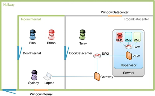
On the physical layer, this scenario is comprised of two rooms, RoomInternal and RoomDatacenter, and a Hallway, where controlled access is possible from the outside to the Hallway and from the hallway to RoomInternal and from there to RoomDatacenter. Both rooms have a window each, WindowInternal and WindowDatacenter, which are usually closed and locked.
On the technical infrastructure layer, the actual cloud infrastructure is exemplified by a physical server Server1, on which three virtual machines VM1, VM2, VM3, a virtual switch SW1, and a virtual firewall VFW are running on top of a Hypervisor. These virtual components are connected to physical network components, namely another switch SW2 and a Gateway. Through this connection it is possible to reach the physical and virtual infrastructure from the Laptop.
The confidential document fileX is located in the storage of VM1. Its rightful owner is Ethan, working in the organized crime department. Other actors include Finn, a member of the finance department, using VM2 for their work, Terry, a technician of the IT support group, and Sydney, a system administrator in IT support. Terry has physical access to the datacenter, whereas Sydney has full logical access to all elements of the cloud infrastructure.
Additional details like power supply, cooling, and so on have been omitted in order to keep the scenario simple, but could be modeled as resources in a real environment, as they may facilitate alternative attack scenarios.
3 The TRESPASS project
Current risk management methods provide descriptive tools for assessing threats by systematic brainstorming. Identifying and consequently preventing attack opportunities in this approach is heavily based on the defenders being able to conceive those opportunities. In a not too volatile world, this reactive approach has proven to work.
However, in today’s dynamic attack landscape, this process is often too slow and exceeds the limits of human imaginative capabilities. Emerging security risks demand tool support to predict, prioritize, and prevent complex attacks systematically.
The TRESPASS project (TREsPASS, 2012) aims at supporting the identification of attack opportunities by building an “attack navigator.” Like a navigator in the real world, an attack navigator works on a map (of an organization) and computes a route (an attack) for reaching a goal (an asset), taking the mode of transportation (the attacker) and the road network (the infrastructure) into account.
Such a navigator would indicate which attack opportunities are possible, which of them are the most threatening, and which countermeasures are most appropriate. To this end, the project combines knowledge from technical sciences, for example, how vulnerable are protocols and software, social sciences, for example, how likely are people to succumb to social engineering, and state-of-the-art industry processes and tools.
One of the goals in TRESPASS is to develop models that capture the essentials of an organization and its structure, namely the map for the attack navigator. This map represents an organization on three core levels: the physical, digital, and social domains. The model thus contains entities, attributes, and relations that are relevant for analyzing the organization’s security. For validating the results from the TRESPASS project, one of the case studies used is based on a cloud environment similar to the one described in this chapter.
The layers described in Section 2 map to the domains just mentioned. The physical and digital domain represent the technical infrastructure (first layer) and the physical environment (second layer), and the social domain represents the third layer.
The socio-technical security models are at the heart of the technical part of TRESPASS, and constitute the interface between the organization being modeled and the processes and tools developed in other parts of the project, such as the analysis tools, and the visualization tools. For the integration into risk assessment frameworks, the models developed in TRESPASS are the entry point into the TRESPASS process.
Models of organizational infrastructures have been used before, for example, for identifying insider threats and attacks on organizations (Probst and Hansen, 2008; Dimkov et al., 2010; Pieters, 2011). An important aspect of these models is modularity, not only to support modular model development and maintenance, but also to support compositional analysis of the models being developed. The modularity of the TRESPASS socio-technical security models allows features to be added on demand; features such as detective components, for example, are optional and only added when needed for modeling the organization.
4 Modeling the scenario for analysis
In this section, we give an introduction to how to model organizational infrastructures in the TRESPASS model. For space reasons we only cover the example introduced in Section 2 and discuss some of its peculiarities; more general discussions can be found in related work (Dimkov et al., 2010; Probst and Hansen, 2008).
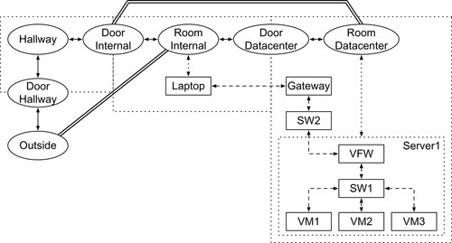
Modeling the scenario from Section 2 and Figure 1 turns all infrastructure locations, independent of their kind, into nodes in a graph. For the physical infrastructure, this results in the graph shown in Figure 2.
As is usual in modeling, the TRESPASS model offers multiple dimensions along which granularity can be adjusted. For example, dealing with virtual connectivity versus physical connectivity quickly leads to difficult questions with respect to the modeling of intermediate nodes and steps in establishing a connection. If connectivity was to be modeled as end-to-end, then every computer would be a room with a door for every other computer in the system. Apart from the obvious connectivity problem, it would be prohibitively difficult to discover vulnerabilities that involve a compromised intermediate node.
Also, different classes of vulnerabilities require different levels of detail in modeling; if redundant paths between two components are available then all nodes on either path are potential sources of data leaks, but denial-of-service attacks will need to involve some combination.
The TRESPASS model unifies the representation of building infrastructure and compute infrastructure. Nodes in the model of a building represent rooms or control points such as card readers; nodes in the model of a computer network represent computers, firewalls, switches; edges in both models represent connectivity; actors in the model of a building represent employees; actors in the model of a network represent programs; nodes can be annotated with policies that limit accessibility based on credentials that an actor provides.
When modeling cloud infrastructures these considerations lead to models that represent Layer 2 connections as “doors”; in this view, connections between computers are abstracted as connections between nodes with communicating processes, with access on each door controlled with checks on the identity and/or actions of the actor. There is an important difference between a person in a building and the way we model network connections: the person is free to make decisions in the rooms, while the connection is not. In the model this means that the person is “just” a node, while the connections are a predetermined process that realizes the functionality in question.
The model of a physical environment might permit an actor to pass a door if the actor is in possession of the necessary credentials, but it would not restrict the actions of that actor once access has been granted.
A firewall, on the other hand, may allow incoming connections from any user over port 80 on a web server, and also from authorized users to port 21 on an FTP server. However, after gaining entrance, a web connection cannot change into an FTP connection to a different server; the actions permitted for an actor depend on how that actor gained access to the room.
Modeling network connectivity requires further modeling artifacts; the routing and automatic forwarding of packets as encountered in network communication can be represented by processes in the TRESPASS model (Probst et al., 2007). In the most simplistic case in a physical model, processes trigger direct actions; for example, an actor who knows a password and has physical access to the computer can access a file that is known on the computer. In general, and especially when modeling network connectivity, we use a more complex configuration in which actions trigger other processes.
Consider the case of two systems, A and B, connected through a firewall router R. If A sends a message to B then the message passes through R without A being aware of that. When A’s message to B is received by R, the processes implemented in R may decide to send a message to B that contains the request from A. By implementing this in processes, the contents of the message sent to B depends completely on the actual message for which R allowed A to have access.
Compare this approach to modeling the firewall by granting A access to R, and then allowing a new process to start from location R. Such a model would find false positives (i.e., attacks that are consistent with the model, but not actually possible) in which a stream arrives at the router as “https” but continues as “ssh.” Attacks where traffic is admitted with one destination address but then continues with a different destination would also be possible within the constraints of such a model, although these would not normally be practical on an actual router.
While the automated processes avoid false positives in which a network device becomes a staging point for a two-phase attack, they do still permit the detection of attacks in which a device is controlled by the remote attacker. In the cloud model, R might allow any “ssh” traffic destined for B. If the user U at A knows an ssh password for B, then the processes would respond with success, adding an attribute to A that from this location user U can control B via “ssh.” If another server, C, allowed anonymous HTTP connections from internal servers only (i.e., any user with control access to B can retrieve some file from C) then an attack would exist in which a user with physical access to A could get the credentials and could access the content on C although A would not have been able to connect with C directly.
In the TRESPASS model, state information can be retained for actors and locations. In the example above, access permission for U from location A to location C is stored at A. Alternatively (or additionally) it could have been stored at U that access is available to C from A. By convention, we store location-bound information in the location, even if it is also bound to an actor.
On a technical level, the TRESPASS model stores state information and access policies in tuple spaces (Probst and Hansen, 2008), which are part of the underlying process calculus Klaim (de Nicola et al., 1998), as are the process components mentioned above.
4.1 High-level model
When modeling the cloud scenario as shown in Figure 1, we need to represent the different entities from the layers introduced above.
4.1.1 Infrastructure
As discussed above, infrastructure is essential to both the model and identifying attack vectors; it represents both physical locations and network locations; the actual hardware enabling data connections can reasonably be modeled in the same way as a host, that is, as a location, but with fewer actor-initiated processes. The virtual equivalents to physical routers, switches, firewalls, and so on are also modeled as locations that are co-located with a host.
A server (virtual or otherwise) is therefore modeled as a location object. In the case of a virtual machine, it is co-located with a host that is also a location. In the example in Figure 2, Server1 is an example for a host that serves three virtual machines.
In practice, many infrastructure devices are extremely sophisticated and flexible. An actor with access to the console and with knowledge of the administrative password could easily use such a device as an entry-point to an attack.
4.1.2 Actors
Actors represent attackers, defenders, victims, collaborators, and any other human factor relevant to the scenario modeled. The concept of actor in the TRESPASS model is however quite general, in that it also represents processes such as an ssh service as an actor; this is natural since processes perform actions in the model and can roam the model.
4.2 Middle-level model
In the high-level model many internal details are hidden from the modeler. For example, the handling of network packets is implicit; a process at a location only sends a packet with a destination address, and as in real life does need to consider the connection with that destination. The middle-level model realizes the sending and actual routing of packets.
The benefit of hiding this from the high-level model is two-fold. On the one hand, the actor does not have the possibility to access and change packets, so on this level a man-in-the-middle attack that changes packet contents cannot be crafted. On the other hand, this attack is of course still possible and can be identified in this middle-level model.
It is important to notice that many of the functionalities modeled in the middle-level model can be extracted from the actual network and cloud infrastructure, or from access-control configurations in the infrastructure.
4.2.1 Routing
The routing processes model and reproduce IP forwarding by automatically generating the outgoing action when the incoming action is accepted. These processes are instantiated based on network masks, and cannot be changed by actors in the network.
For modeling network connection in a general model, IP is an appropriate choice not only because it is a good solution for carrying out hierarchical routing, but also because it is the protocol actually in use in cloud infrastructures and networking in general.
4.2.2 Network traffic set-up
By implementing network access as a chain of processes, and by using pessimistic routing of the traffic (c.f. Section 4.4.3), any side effects of network access will be detectible as a side effect of incorporating it in an attack path.
If in the example shown in Figure 1 a goal of the system is that the user at Laptop should have access to VM1, then the attack generator, trying to invalidate this goal, will be able to identify processes that disable intermediate nodes (such as the firewall VFW) as an attack. Similarly, if another goal is that this access must be private, then other systems to which the network traffic of that access may be visible will be able to use it to trigger interception processes that would qualify as an attack.
4.2.3 Flow-based access control
Routing connections through intermediate nodes allows flow-based access control, such as may be provided by firewalls, to be implemented with rules that correspond to the actual configuration of the corresponding physical devices. The data in and out of a model component that represents a firewall can be altered, redirected, or dropped without explicitly incorporating these possibilities in how the endpoints are modeled.
As mentioned above, the initial configuration of flow-based access control will usually be extracted from the actual devices in the network or cloud infrastructure.
4.3 Low-level model
Finally, at the lowest layer we need to model the actual services running on nodes in the network. This can for example be used to link services to vulnerability databases.
As outlined at the beginning of this section, and detailed below in Section 4.4, network traffic is modeled by triggering processes on the various nodes along a route. The service at the destination is again represented as a process that triggers some computation and the return message.
For example, an SSH connection request from the Laptop to VM1 in Figure 1 will trigger a series of repetitions along the chain of intermediate nodes between the source and the destination. If permitted by the intermediate nodes, eventually this will trigger a process at the destination node VM1 that triggers a connection acceptance message. That result is then returned to Laptop by a series of triggered processes back to the initiator. The process that will be waiting to be triggered at the initiator upon receipt of the acceptance message will register the connection.
4.4 Modeling typical network components
Using the different modeling levels just introduced, we will now show how typical components found in networks can be represented.
4.4.1 Routers and routing
Data routing follows the same general method as IP routing, matching destination networks and replicating traffic to the next hop. Where more than one path would be possible, traffic will be sent over all available (acyclic) paths. Although the routing uses IP addresses, it is implemented on a Layer 2 network topology. This will ignore potential data leaks via ARP broadcasts, but is generally a sound model for how the packet will travel.
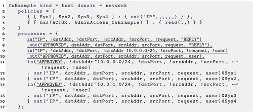
For example, assume VM1 and VM2 in Figure 1 to have IP addresses 192.167.1.1 and 192.167.1.2, respectively. Both nodes are part of network 192.167.1.0/24, and are connected by switch SW1 with a default gateway on VFW. The resulting basic model is part of Figure 2 and the textual representation of the involved processes and policies is shown in Listing 22.1.
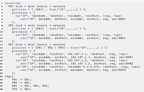
Each node is annotated with its kind and its domain, and has a policy and processes. The policies specify which other nodes are allowed to communicate with this node, and which form of messages are allowed to be sent; policies basically realize the network infrastructure and the kind of protocol supported. For example, SW1 accepts packages from VM1, VM2, or VFW in the form of IP packages. Policies thus specify the trigger points introduced above, through which communication can happen.
The processes specify how the node reacts to triggers, basically by describing how to react to different kinds of messages received. This is similar to pattern matching. For example, the node SW1 defines three processes that are all triggered by receiving an IP message. For the sake of simplicity we assume that all packets have the form of 7 tuples consisting of the tag “IP,” the source address and source port, the destination address and destination port, the request, and a user name. Depending on the scenario in question this can be adjusted. Each routing process consists of inputting a tuple based on a pattern, and routing the tuple to the correct next hop. Processes use the exclamation mark for binding variables to values and the ∼ operator for matching addresses. Processes are ordered by mask size, so the first match is the route taken. Empty tuple elements are wildcards, so ("TAG", 192.167.1.1, "Content1", "Content2") would match ("TAG", !addr∼192.167.0.0/16,,) while binding the variable addr to the address 192.167.1.1.
For the specification in Listing 22.1 the switch SW1 sends packets for VM1 and VM2 directly to them, and packets for any other address to VFW.
4.4.2 Defining a service
Once we can route packets to the correct location, we need to be able to consume (or refuse) the operation. As mentioned before, the constant "IP" in the first parameter of the routing processes is used to differentiate the events in transit from services. When a packet reaches its end destination and if that particular location has a service listening on the destination port, then the packet is consumed. Whether the service is available to a specific user can then be determined with a policy for that service. In this way, the access control for the network is separated from the access control for services.
For example, if VM1 is running an FTP daemon on port 20, then we can define a receiver as shown in Listing 22.2. These processes describe terminating the request to port 20 by passing it to an FTP process, retrieving the file, and giving it to the requesting user. Access to that service can then be controlled with the policy for in("FTP",,,,).
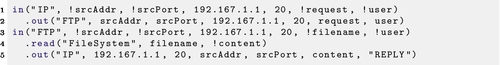
The user is changed to the constant value "REPLY" for the return traffic. This allows firewall rules to emulate normal firewall behavior, allowing return traffic for existing connections.
In this case, if anonymous FTP is available on VM1 for the asset fileX, the policy on VM1 would look like this
{ [ VM1 ] : { out("FTP", , , , , "fileX", ) } }
If the asset fileX was protected by a password secret, then this could be modeled as:
{ [ VM1, has(USER, "secret") ] : { out("FTP", , , , ,"fileY", USER) } }
where USER is a free variable that is bound when evaluating policies and secret is the password of the file being protected.
4.4.2.1 Generic service access
Adding a generic IP process to each host allows IP traffic that reaches the host to be identified even if it does not reach any specific service. For example, host 192.167.1.1 might have policies as shown in Listing 22.3.
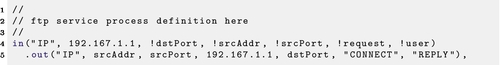
This additional process does not need any additional policies, as it matches the normal IP tuples. It returns a constant value "CONNECT", which can be used to model basic connectivity.
4.4.2.2 Administrator access
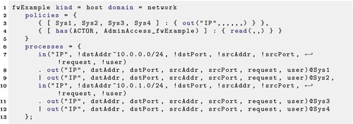
Differentiation of access rights based on knowledge of passwords can be modeled through policies, granting the actor the ability to directly access data stored on the machine. Note that this does not interfere with the defined services, but covers direct physical access or from a login shell; therefore the policy for this access does not use the "IP" tuples. A policy line with the following form is added to all servers:
policies = { [has(ACTOR, "admin_password")] : {read}} where ACTOR is a free variable that is bound when evaluating the policy and admin_password represents the actual administrator’s password. This allows requests for any non-destructive read from the server location itself that are initiated by an actor who knows admin_password.
4.4.3 Switch versus hub
Technically, a switch does normally behave as described in Section 4.4.1. Once it sees IP traffic to a particular address being accepted by a directly-connected device, further traffic to that address is sent to that device only. In practice, however, it is possible for devices to alter their own IP address to conflict with another device on the same subnet, and generally to interfere with the normal flow of data.
Although hubs, which repeat all incoming traffic to all other interfaces, are not used much in the 21st century, modeling their behavior allows for a more conservative security assessment. This is achieved by changing processes implementing the switch shown above to the ones shown in Listing 22.4.
Another approximation of reality is that switches (and hubs) are not specifically aware of their subnet mask so, by the argument above, they should echo all packets to all neighbors. In our actual modeling, they echo to all neighbors for local traffic only. This is meant to reflect the relative difficulty of intercepting traffic from a server to a router, or between two routers.
If we classify an attack that is able to intercept traffic to a router as a compromise of the router, then attacks on this traffic are staged attacks that first require the router to be compromised, and then intercept the traffic to that router.
4.4.4 Firewalls
Firewalls play an integral role in network security. Normal best-practices deployment of firewalls separates not only inside from outside, but also separates sections of an internal network. This deployment philosophy is very similar to the use of their original namesake in building design, limiting the scope of damage likely to result from a single incident.
In modern network appliances, a firewall is just one aspect of a “Unified Threat Management” appliance that offers various services, including NAT, load balancing, and routing. The functionality of the actual firewall goes beyond simple allow/deny rules based on protocol, address, and port; deep-packet inspection, protocol validation, external black-lists, and HTTP header filtering are all useful and common firewall services. While these other services have implications on network security, the present analysis focuses on the traditional allow/deny for a given protocol on a given source and destination address and port. Adding more extensive checking can be modeled by processes in a way similar to routing described above.
As mentioned above, routing is implemented on a worst-case assumption that any acyclic path might be used. This can be determined from the network topology without internal configuration details of the routers. The firewall behavior cannot be guessed in this way, since its behavior even in the simplest case goes beyond routes. The analysis therefore requires a read-only interface to the extract the configuration from whatever firewall model is in use. In the current tools, we are supporting Cisco ASA firewalls, both physical and virtual.
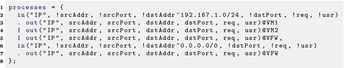
After parsing, the firewall model is an extension of a basic router. For example, Listing 22.5 shows a Layer-3 switch. In this example, all traffic received for either of the attached networks will be repeated to the destination network. If this appliance were acting as a firewall that allows no incoming connections to 10.0.1.0/24, this could be built as in Listing 22.6. Notice that returning traffic, which will have the user set to the constant “REPLY” is still routed, but new connections will be ignored.

One approach to modeling firewall behavior would be to build what amounts to a custom routing table for every permitted flow. In a normal firewall with one interface on each connected network, this would build a correct model, but tying the routing to the flow rules will make it difficult for a human to read, especially if some subnets are connected to more than one interface.
In order to separate routing from flow rules, we have introduced a layer of indirection in the firewall processes relating to IP traffic, as shown in Listing 22.7.
4.4.5 VPNs
Not every switch is a router, and not all traffic arriving at a Layer-3 switch is routed. If half of the ports on a particular Layer-3 switch are assigned to VLAN 10, and the other half to VLAN 20, then that switch represents two broadcast domains. If it also defines an interface in each of these domains, then it may route traffic between them, but it does not need to.
VLANs are assigned to ports, which correspond in this model to the identity of the device being communicated with. This is difficult to model because the identity of the partner is referenced in the policies section, but not where routing is implemented in the processes section. At least two solutions are available: anti-spoofing and greater partitioning.
Anti-spoofing can be implemented by including a source address mask in the policy for each partner system in a particular VLAN. Messages can be accepted if and only if their source address is from an address known to be local to (or reachable from) that VLAN. If this is in place, then the source addresses can be used to filter traffic in the policy, preventing communication to leak between VLANs.
The problem with the anti-spoofing solution is that it may not be how the actual device is implemented. If the device itself does not have an anti-spoofing service, then including it in the model of that device may be trading potential false positives for potential false negatives. For example, the example in Listing 22.7 would allow a device in 10.0.0.0/24 to spoof a source address in 10.0.1.0/24 to successfully send a packet to 10.0.1.0/24. It would not receive the reply, but some attacks do not need to receive a reply.
An alternative to including anti-spoofing in the policies would be to implement each VLAN on a switch as a separate device. Logically, this is close to an accurate representation of the topology, but it may make it difficult to place firewall rules, and will certainly make it difficult to model trunking.
The best solution for modeling any particular topology will depend on how the switch is being used in that installation.
4.5 Modeling actors
Like locations, actors have knowledge stored in tuple spaces and defined processes that may be triggered when operations are performed on those tuplespaces. Actions will most often be associated with the transfer of knowledge or physical objects, but the tuplespace itself will also hold information about the actor.
4.5.1 Actor processes
One of the most basic actions for an actor would be to transfer knowledge to another actor. This action needs an initiator, and there is no strong argument for which party (the giver or the receiver) that should be, so let us arbitrarily decide that the action is initiated by the receiver making a request. In Listing 22.8, Sydney is capable of telling his password to others.
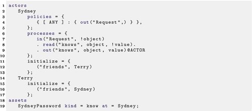
The “initialize” block in Listing 22.8 initializes the contents of the tuplespaces of Sydney and Terry (discussed more below in Section 4.5.2). The assets block also implicitly populates the initial tuplespace of Sydney with a tuple of the form ("knows", SydneyPassword, "SydneyPasswordValue").
4.5.2 Non-process attributes
In the example of Listing 22.8, the tuplespaces of actors Sydney and Terry hold the information that these two actors are mutual friends. This information does not directly affect any processes, but can be used during the attack generation to annotate attack scenarios. In this case, it may be that the action of transferring a knowledge asset from one actor to another is more likely if those two actors are friends.
4.6 Process library
The possibility of transferring a knowledge asset from one actor to another (people telling other people things that they know) is generally present. It may be more difficult for some assets (knowledge of a floor plan is harder to communicate than knowledge of a password), and more likely for some actors (depending on security training level, relationship status, etc.), but the basic operation is generally possible. Technically, repeating the definition for every actor is a possible solution, but it would clutter the model and greatly reduce the model’s readability and auditability.
To circumvent this, a process library of standard processes and policies is therefore used to capture common standard behavior. This standard behavior is applied wherever relevant.
5 Identifying attacks
The goal of formalizing the model of an organization and its IT infrastructure as shown above is to guide attack generation and, based on those attacks and their impact, risk assessment (c.f. Section 6). From the viewpoint of this chapter, attack identification is a black box; we briefly discuss its working for completeness (for alternative approaches, see e.g., Sommestad et al., 2013 or Kriaa et al., 2012).
Based on the model of the organization, we use “policy invalidation” (Kammüller and Probst, 2013) to identify paths by which a system-wide policy can be broken in the modeled organization. An important property of the attacks we want to find is that they span the social, physical, and virtual domain; an attacker can use actions in all three domains to reach their goal, and the attack generation should be able to identify and generate these steps.
Policies have surfaced several times before; in our model they are either associated with the overall system or with individual nodes. Policies at a node in the graph represent access control points; they are also used to trigger processes as described in the previous section.
The policy to invalidate can be specified as part of the model, or we can try to invalidate all policies in the model. The former approach results in a relatively targeted set of attacks, while the latter, though exhaustive, may contain many attacks that are not of interest. In parallel with the invalidation, one can also generate attack trees (Schneier, 1999) for the identified attacks.
In the example from Figure 1, the attack considered is that an adversary is able to access the confidential file fileX. A typical organizational policy could be that confidential files are not allowed to leave the organization’s perimeter, here identified by the organization’s building infrastructure. In the model of the scenario shown in Figure 2, the area outside of the organization’s perimeter is represented by the node Outside. The goal policy would then be translated to
goal = not fileX@Outside
Goal policies can be more complex; they can contain first order logical formulae with predicates, but for space reasons we limit ourselves to this rather simple example. Therefore the goal function above abstracts from reality; it can be seen as a representative for policies such as that non-employees are not allowed to know the file contents. This would require a more detailed model containing employees and non-employees, as well as the actual content of the file. The latter would also support modeling encrypted files.
On a high level, the attack generation performs four major steps:
• First, identify a policy to invalidate; this results in actors who might perform the attack, along with a series of pairs that identify actions to perform and locations at which to do so;
• Next, identify the required assets to perform this action; and
• Generate attacks for obtaining these assets.
• Finally, the attacker moves to the location identified for the first step and performs the action.
This attack generation starts from a goal policy and works iteratively until the prohibited action can be performed. For the organizational policy in the example scenario described above, the attack generation identifies a number of possible attacks:
• The rightful owner Ethan takes the file outside.
• The system administrator Sydney uses his access rights to make a copy of the file.
• The technician Terry removes the server from the server room.1
• The financial accountant Finn accesses the file from VM2.
• Sydney or Terry place a wire tap on the network to observe the traffic.
• Ethan, Sydney, or Terry are social engineered to perform any of the above actions.
• Terry is being social engineered to let an adversary into the server room. This requires that somebody let the adversary into the building and into the internal room.
• An adversary observes Sydney’s password being typed into the laptop and uses it to get access.
• An adversary breaks a combination of the doors and the windows to get physical access to the server room.
The attack generation will result in an attack tree representing all these attacks as options in the tree. In the TRESPASS project we are currently developing techniques for generating attacks for socio-technical systems. For technical systems similar approaches exist (Vigo et al., 2014).
6 Risk assessment
The previous sections have introduced a model for cloud infrastructures as socio-technical systems and a process for identifying attacks in those systems. The attacks identified on the model together with the model form the basis for risk assessment of the system. Being based on both the model and the attacks, the risk assessment can take a number of factors into account. These factors can originate from either the model or the attacks, or from a combination of both (Probst and Hunker, 2009; Probst and Hansen, 2013).
All the approaches to risk assessment presented here benefit from the automatic extraction of the cloud infrastructure part of the model, which makes dynamic updates of the risk assessment straight forward and easy to automate. This automatic extraction and auditing of infrastructure information from cloud infrastructures will become increasingly important in risk assessment (Bleikertz et al., 2010; Probst et al., 2012).
Besides the model and the attacks, the risk assessment is based on additional information similar to traditional risk assessment approaches; for example, it requires a valuation of assets and an estimate of the likelihood that certain events occur. The valuation is used in computing the potential impact of an identified attack. The estimated likelihood can be used for sanity checking of results of the risk assessment and the attack generation. If the predicted numbers differ significantly from the observed numbers this difference should trigger an examination.
6.1 Model-based risk assessment
When taking only the model into account, risk assessment can be based on the reachability of assets that should be protected or that occur in organizational policies such as the one presented in the previous section. On this level, the risk assessment is mostly based on paths through the system graph as shown in Figure 2 for the example scenario.
Being graph based, identifying paths and computing metrics on them is straightforward (Probst and Hansen, 2013). Basing the risk assessment exclusively on the model will result in imprecise results at best; nevertheless the results will support a very quick identification of problematic or areas at risk in an organization to pinpoint further, more detailed investigations.
6.2 Attack-based risk assessment
Risk assessment can also be based exclusively on the identified attacks. Similarly like the model-based risk assessment the results will only be indicative; they do not relate an attack and its impact to infrastructure, actors, and assets, nor to policies.
Attack-based risk assessments computes likelihood and impact for the identified attacks, taking the valuations of assets and the estimated likelihoods for events into account. Other properties of attacks that can be of interest include minimum and maximum time to perform an attack, required resources or skill level, or likelihood of detection. The result of this assessment is a list of attacks ranked on any of the computed properties of the attack.
The attack-based risk assessment supports identification of endangered assets and policies that are likely to be violated; it also provides additional metrics as described above. Since the attack tree will be based on actors in the model, their actions, and locations in the model, the attacks can also be combined with the model; this approach results in the third kind of risk assessment.
6.3 Combined risk assessment
The attacks described in Section 5 consist of sub-attacks by actors that obtain necessary assets such as keys to perform actions, and of these actions being performed. Consequently there is a direct relation between the model, providing the actors, locations, and assets, and the generated attacks plus their computed properties as described above.
The combined approach to risk assessment utilizes the model-based evaluations (Probst and Hansen, 2013) and extends them with the computed attack properties. This approach provides a more detailed insight into the contribution of parts of the model to different attacks, and thus supports a better understanding of the risk that areas of the modeled organization either are exposed to or pose by contributing to attacks.
Mapping the attack properties to the model often results in common areas of a model to have a very high risk of contributing to attacks; in the model shown in Figure 2, the hallway will contribute to all attacks that require physical access. This kind of result will often represent unwanted artifacts that can be ignored.
On the other hand, most attacks identified in Section 5 involve network-based access through at least the switch SW1 or also other nodes in the network infrastructure. This will result in SW1 getting a high contribution to potential attacks; this node or the traffic through it might be subjected to additional logging. The only attacks not involving the network infrastructure are the ones where the hardware storing the file is physically removed.
7 Conclusion
Assessing risk in cloud infrastructures is difficult. Cloud infrastructures can be very big, are highly interconnected, and very dynamic. They contain network infrastructure nodes and computing nodes, and they also are integrated in some way into organizations; this integration can be directly, that is, the cloud being operated by the organization and being accessed through the local network, or indirectly, that is, the cloud being operated by a cloud provider and being accessed remotely. In either of these scenarios human actors become an essential part of the whole system.
In this chapter, we have presented a modeling exercise for socio-technical systems, introducing a process developed in the TRESPASS project. The model for the cloud infrastructure captures details at several levels and can represent typical artifacts. Using this model, we have discussed how to identify potential attacks and how to integrate them into risk assessment.
One attack possibility that is not covered in our approach yet are attacks on policies or processes, where an actor with administrator rights maliciously or by accident changes parts of the system to give access to adversaries. We are currently working on extending our system with such meta-rules.
If risk assessment in complex technical infrastructures already is difficult, it is even more complicated when adding human factors and physical infrastructure into the setup, which therefore often are ignored (Probst and Hunker, 2009). Using automated extraction of network infrastructure configurations, our approach not only supports on-the-fly risk assessment of cloud infrastructures; it also supports analyzing the combined soco-technical system consisting of the organization, its employees, and assets, including for example staff at a remote cloud operator.