
Chapter 5
Notch Crossovers
The crossovers examined in Chapter 4 are all-pole crossovers, which means that the filters used are relatively simple lowpass and highpass types, though of varying order and filter characteristics (Butterworth, Bessel, etc). It is also possible to contrive crossovers that have notches (or to get mathematical, zeros) built into the roll-off, typically giving a much steeper filter slope, to begin with at least, than an all-pole crossover of a practical order. This can be very useful when drive units that are otherwise acceptable misbehave badly when taken just outside their intended operating range. Neville Thiele [1] gives the example of a horn loudspeaker being used near its cutoff frequency. He also cites the case of a mono subwoofer, where its contribution must be rolled-off as quickly as possible out of band to prevent it contaminating the stereo localisation cues from the main speakers.
Elliptical Filter Crossovers
A 4th-order crossover design based on the use of elliptical filters was published by Bill Hardman in Electronics World in 1999, [2] and this has been the basis for much discussion on the subject. The amplitude response of the published design is shown in Figure 5.1.The original version had a crossover point at 1.5 kHz, but I have modified the filter frequencies for 1 kHz instead, to match all the other crossover response examples in this book. Nothing else that might affect the response has been changed.
The two deep notches symmetrically placed on either side of the crossover point are at 529 Hz and 1.84 kHz, less than an octave away from the crossover point. It is obvious that their presence greatly increases the initial roll-off slope, making it more effective than a 4th-order Linkwitz-Riley alignment from this point of view.
It is, however, vital that the outputs of a crossover should sum to as nearly flat as possible, and looking at the spiky nature of Figure 5.1, you are probably thinking that this is going to be very difficult to arrange. In fact it can be done relatively easily. Figure 5.2 shows the in-phase summation; the central hump is only −0.13 dB deep, while the dips on either side are about −0.9 dB deep. The phase-reversed summation has a deep notch at the crossover frequency and is of no value.
Looking at Figure 5.2, one cannot help feeling it might be possible to improve the flatness of the summation by tweaking the filter frequencies. However, applying a frequency offset is in fact not very helpful, because the centre rises much more than the dips do; for example, an offset ratio of 1.045 gives a central peak of +0.4 dB with dips of −0.7 dB, which is not much improvement, if any, on the original Hardman alignment.
The elliptical filters used in this crossover are the usual combinations of notch filters and all-pole filters. Figure 5.3 shows that the lowpass path is composed of a lowpass notch and a 2nd-order lowpass Sallen & Key filter; the latter has equal component values but a non-standard Q, which places it somewhere between a Linkwitz-Riley and a Bessel filter characteristic. The highpass path is composed of a highpass notch and a 2nd-order highpass Sallen & Key filter with the same non-standard value of Q.
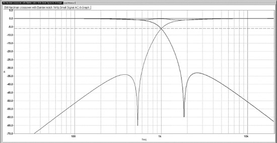


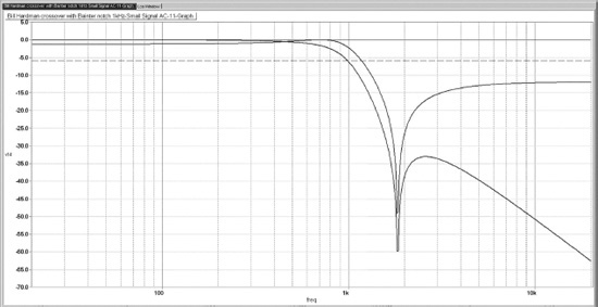
Figure 5.3 underlines the difference between a lowpass notch and a highpass notch. These are not your more familiar symmetrical notches that go up to 0 dB on either side of the central crevasse. A lowpass notch response starts out at 0 dB at low frequencies, drops down into the crevasse, then comes back to level out at a lower gain, say −10 dB; the lowpass notch can be seen in both Figures 5.1 and 5.4. Conversely, a highpass notch has a response that is 0 dB at high frequencies, drops down, then comes back up to, say,−10 dB at low frequencies.
Figure 5.4 shows how it works for the lowpass path. The notch filter provides a lowpass notch; as frequency increases there is some peaking just before the roll-off into the crevasse. This is cancelled out by the low-Q, relatively slow roll-off from the all-pole lowpass filter, giving a fast roll-off around the crossover frequency, and also giving a notch deepened by the increasing attenuation of the lowpass filter. The ultimate roll-off slope, above the notch frequency, is only 12 dB/octave because it comes entirely from the 2nd-order lowpass filter.
The original Hardman crossover used Bainter filters to create the notches followed by 2nd-order Sallen & Key filters. Bainter filters are popular for making elliptical filters of the type shown here because they give good deep notches where the depth does not depend on the matching of passive components, but only on the open-loop gain of the opamps. You can see lovely deep notches in Figures 5.1 and 5.4; it is in a sense a pity that the notch depth is not in any way critical to get a good summed response. So long as a distinct notch is visible the effect on the summed response is negligible.
A design for a Hardman crossover is shown in Figure 5.5. While the essential filter characteristics are closely based on those in the original article, [2] the crossover frequency, as noted, has been altered from 1.5 kHz to 1.0 kHz, and the general impedance level of the circuitry reduced by a factor of approximately 20, to reduce noise. Any further impedance reduction would risk overloading the opamps (assumed to be 5532s) with a consequent increase in distortion. As with many other circuits in this book, it has been designed to use standard capacitor values, with the resistor values coming out as whatever they do. It is much cheaper to get an exact value by combining resistors rather than by combining capacitors. The simplest way to scale the circuit to implement other crossover frequencies is to change all the capacitors in the same ratio.
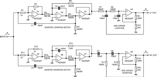
Figure 5.5 shows that the two Bainter notch filters for lowpass and highpass are very similar, with only three components differing in value. This sort of convenient behaviour is what makes the Bainter filter so popular. The relationship between R3 and R4 in the lowpass filter, and between R13 and R14 in the highpass filter, determine the kind of notch produced. If R4 is greater than R3, you get a lowpass notch. If R3 = R4, you get the standard symmetrical notch. If R3 is greater than R4, you get a highpass notch. The value of R6 (or R16) sets the notch Q.
There are however some aspects of this circuit that are less convenient. The lowpass notch response does not actually start out at 0 dB at low frequencies; instead it has a gain of +10.6 there. The response then drops into the crevasse and comes back up to 0 dB. There is then the gain of +1.3 dB from the lowpass filter, giving a total of 11.9 dB of passband gain, which may not fit well into the gain/headroom scheme planned for the crossover.
The highpass notch response has a passband gain of 0 dB at high frequencies, and at frequencies below the notch comes back up to −10.8 dB. With the final highpass filter added the passband gain is +1.2 dB. Therefore we have a level difference of 11.9 − 1.2 = 10.7 dB between the two outputs, and this will have to be accommodated somewhere in the crossover system design. There is more information on the Bainter filter and other notch filters in Chapter 12.
A most interesting paper on the use of Chebyshev filters (ripples in the passband), inverse-Chebyshev (notches in the stopband), and elliptical filters (ripples in the passband and notches in the stopband), with the added feature of a variable crossover frequency, was published in the JAES by Regalia, Fujii, Mitra, Sanjit, and Neuvo in 1987. [3] It is well worth studying.
Neville Thiele MethodTM (NTM) Crossovers
One of the better-known notch crossovers is that known as the Neville Thiele MethodTM crossover, introduced by Neville Thiele in an AES paper in 2000. [1] This does not appear to consist of elliptical filters as such (as far as my knowledge of elliptical filters goes, anyway) but a rather more subtle arrangement that sums to unity much more accurately than the Hardman crossover we have just looked at. One of the few examinations of this technique that has been published is that by Rod Elliot. [4]
I should say at once that the Neville Thiele MethodTM or NTM is a proprietary technology addressed by US Patent 6,854,005 and assigned to Techstream Pty Ltd, Victoria, AU, and that if you plan to use it for anything other than a private project you might want to talk to them about licensing issues. The information given here is published by permission and is derived solely from the public-domain References [1] and [5], which I have to say are not an easy read. I have never seen a schematic of a manufactured crossover using this technology, nor have I ever deconstructed any related hardware.
Using References [1] and [4], it appears that the lowpass path of a 6th-order NTM crossover filter (8th-order versions are also possible) consists of a bridged-T lowpass notch filter, followed by a 2nd-order lowpass filter with a Q of about 1.6; this is followed in turn by two 1st-order filters. This structure, together with the matching highpass path, is shown in Figure 5.6.
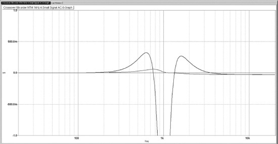
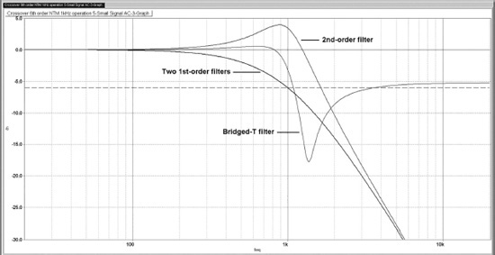
The result of this rather complicated-looking block diagram is shown in Figure 5.7. Each filter output has a fast roll-off after the crossover point, terminating in a shallow notch; the response then comes back up a bit but then settles down to an ultimate 24 dB/octave roll-off. The filter responses may not look very promising for summation, but in fact they do add up to an almost perfectly flat response when the phase of one output is reversed. If summed in-phase there is a central crevasse about 12 dB deep, of no use to anyone.


Figure 5.8 shows a much closer view of the summed response. The bump below the crossover frequency peaks at +0.056 dB, while the flat error in the level above the crossover frequency is at −0.031 dB. Since these very small errors are asymmetrical about the crossover point, it seems more likely that they are due to opamp limitations or similar causes, rather than anything inherent in the crossover. They are negligible compared with transducer tolerances, or with the summation errors of crossovers that approximate flatness by using frequency offsetting; the performance is much better than that of the Hardman elliptical crossover, which has flatness errors of 0.9 dB.
Figure 5.9 attempts to show how the NTM crossover works; the response of each filter stage in the lowpass path is shown separately. (The responses of the two 1st-order filters have been combined into a single response for the two when cascaded.) The bridged-T filter creates a lowpass response that comes back up to −5 dB after it has been down in the notch. You will note that the notch is much shallower than that of the more complex Bainter filter used for the Hardman crossover, but this has only a very small effect on the summed response, and the simplicity of the bridged-T circuit is welcome.
The next stage in the crossover is a 2nd-order lowpass filter with a cutoff frequency of 1.0 kHz and a Q of approximately 1.6. This is quite a high Q for a 2nd-order filter and gives a +4.5 dB peaking of the response before the ultimate 12 dB/octave roll-off. This will need to be taken into account when planning the gain structure; rearranging the order so the 1st-order filters come before the 2nd-order should ease the situation considerably.
The two 1st-order filters both have a cutoff frequency of 1.0 kHz, and so their combined response is down −6 dB at 1.0 kHz, with an ultimate slope of 12 dB/octave. The action of these two stages together is the same as that of a 2nd-order synchronous filter, as described in Chapter 7. If implemented as simple RC networks, they must be separated by a suitable unity-gain buffer to give the correct response.
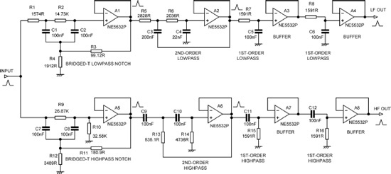
Figure 5.10 shows the schematic of my version of an NTM crossover based wholly on the information given in [1] and [4].
An interesting point is that in each path the two 1st-order filters can be combined into a single Sallen & Key 2nd-order stage with a Q of 0.5, thus saving an opamp in each path. As Figure 5.11 shows, the component values used are exactly the same. This is my modest contribution to the NTM.

References
[1]Thiele, Neville “Loudspeaker Crossovers with Notched Responses” JAES, 48(9), September 2000, p. 784
[2]Hardman, Bill “Precise Active Crossover” Electronics World, August 1999, p. 652
[3]Regalia, Philip A., Nobuo Fujii, Sanjit K. Mitra and Yrjo Neuvo “Active RC Crossover Networks With Adjustable Characteristics” JAES 35 (1/2), January/February 1987, pp. 24–30
[4]Elliot, Rod http://sound.westhost.com/articles/ntm-xover.htm
[5]Thiele, Neville “Crossover Filter System and Method” US Patent 6,854,005 Feb 2005 (Assigned to Techstream Pty Ltd, Victoria, AU)