
Chapter 1
Crossover Basics
I do hope you’ve read the Preface. It is not mere amiable meanderings, but gives an oversight as to how this book is constructed and what it is intended to do.
What a Crossover Does
The basic function of any crossover, be it passive or active, analogue or digital, is to take the audio spectrum that stretches roughly from 20 Hz to 20 kHz and split it into two, three, or more bands so they can be applied to loudspeaker drive units adapted for those frequencies. In hi-fi use the crossover frequencies are usually fixed and intended for work with one particular loudspeaker design, but for sound-reinforcement applications the crossover frequencies are normally variable by front panel controls.
There are also other functions that are sometimes but not always performed by crossovers, and we may list them all as follows, roughly in order of importance:
- Equalisation to correct drive unit frequency responses
- Correction for unmatched drive unit sensitivities
- The introduction of time delays into the crossover outputs to correct for the physical alignment of drive units
- Equalisation to correct for interactions between drive units and the enclosure, e.g. diffraction compensation
- Equalisation to correct for loudspeaker-room interactions, such as operating in half-space as opposed to quarter-space
- Enhancement of the natural LF response of the bass drive unit and enclosure by applying controlled bass boost
Most of these functions are equally applicable to both passive and active crossovers, but the time-delay function is rarely implemented in passive crossovers because it requires a lot of expensive components and involves significant power losses.
Some of these functions will probably appear wholly opaque if you are just starting this book, but stay with me. All will be revealed.
Why a Crossover Is Necessary
The need for any crossover at all is rooted in the impracticability of making a drive unit that can handle the whole ten-octave audio spectrum satisfactorily. This is not merely because the technology of loudspeaker construction is inadequate but is also rooted in some basic physics. Ideally the acoustic output of a loudspeaker would come from a single point; with such a source the sound field is uniform, because there can be no interference effects that result from multiple sources or from a source of finite size.
A tweeter has a small physical size, with a dome usually around an inch (2 or 3 cm) in diameter, and approximates fairly well to a point source. This technology works very well for high frequencies, say down to 1 kHz, but is hopelessly inadequate for bass reproduction because such a small area cannot move much air, and to reproduce bass frequencies you need to move a lot of it. Low-frequency drive units are therefore of much greater diameter, up to 12 inches for domestic hi-fi and up to 18 inches or more for sound-reinforcement applications. As cone area is proportional to the square of diameter, a 12-inch drive unit has 144 times the area of a typical tweeter, and an 18-inch unit has 324 times the area.
It is not at present technically possible to make a big low-frequency drive unit that works accurately up to 20 kHz, because as the frequency increases the cone ceases to move as a unit—it is not one of those most desirable “infinitely rigid pistons” that are always cropping up in loudspeaker theory but never in manufacturer’s catalogues. This effect is often called “cone break-up” not because the cone physically falls apart but because, due to its finite stiffness, with rising frequency its surface divides up into separate areas of vibration. This unhappy state of affairs is put to advantage in so-called full-range loudspeakers which have a “parasitic tweeter” in the form of a small cone attached to the voice coil. The idea is that at higher frequencies the main cone does its own thing and is effectively decoupled from the voice coil and the tweeter cone, allowing the latter to radiate high frequencies without being restrained by the much greater mass of the main cone—what you might call a mechanical crossover. As you might imagine, there are many compromises involved in such a simple arrangement, and the response is generally much inferior to a good 2-way loudspeaker with separate bass unit and tweeter.
Nonetheless, the field of audio being what it is, there are a certain number of hi-fi enthusiasts who advocate full-range speakers for various reasons. Eliminating a passive crossover naturally increases power efficiency (as none is lost in the crossover components) and reduces cost.
Beaming and Lobing
Even if it was possible to make a large-diameter drive unit which covered the whole audio spectrum perfectly, there is a powerful reason why it is far from certain that this would be a good idea. If a radiating surface is of finite size, then if you stand to the side of the central axis, sound from one area of the drive unit will arrive at your ear at a slightly different time compared with another area because of the differing path lengths through the air. This will cause interference between the two signals and, given the right amount of path difference, complete cancellation. There will therefore be major irregularities in the frequency response anywhere but on the central axis. This is called “beaming” or “lobing”, and it occurs when the diameter of the radiating object is comparable with the wavelength of the sound. It is obviously to be avoided as much as possible; the variation in response as the angle between the listener and the centre axis changes is called the polar response, and a “uniform polar response” is much sought after in loudspeaker design.
|
Driver Diameter (inches) |
Beaming Onset Frequency (Hz) |
|---|---|
|
1 |
13,680 |
|
2 |
6840 |
|
5 |
3316 |
|
6.5 |
2672 |
|
8 |
2105 |
|
10 |
1658 |
|
12 |
1335 |
|
15 |
1052 |
|
18 |
903 |
The beaming phenomenon is why a tweeter has to be of small diameter if it is to approach having a uniform polar response. Deciding when beaming becomes significant depends on the application, but the figures in Table 1.1 [1] have been put forward as shown above.
These frequencies are approximately those at which the wavelength in air equals the driver diameter. The whole business of beaming, lobing, and polar response generally is obviously much too complex to be summed up in a single table, but it does give some indication of when you need to start worrying about it.
There is of course much more to a crossover than simply splitting the audio signal into separate frequency bands. The vital point to understand is that the splitting has then to be followed by summation. The frequency bands have to be joined together again seamlessly. This requires the acoustic signals be summed to be correct not only in amplitude but in phase. The crossover and speaker system can only create the exactly correct signal at one point in space, which is unfortunate, as we have two ears and each listener therefore needs the signal to be correct at two points in space. Crossover design is always a matter of compromise to some degree.
It is not sufficient to get a perfect response on-axis, even if one interprets this as being capable of summing correctly at both ears. The off-axis output from the loudspeaker will not only be heard by those in the room unfortunate enough to not get the best seat on the sofa, but it also creates the ambient sound environment through room reflections and reverberation. If it has serious response irregularities, then these will detract from the listening experience, even if the direct on-axis sound is beyond reproach.
The term “lobing” is also used to describe the reinforcements and cancellations that occur when two separate drive units are radiating; in this case their size is relatively unimportant because interference would still occur even if both were point sources. When the radiation pattern is shifted at the crossover frequency because the signals to the two drive units are not in phase, this is called “lobing error”. There is much more on this in Chapters 3 and 4.
Passive Crossovers
Passive crossovers use only passive components, mostly capacitors and inductors. Resistors are also sometimes used, and the inductors are sometimes elaborated into auto-transformers, often with multiple taps for setting LF/HF balance. Figure 1.1 shows a typical 2-way crossover with a couple of common elaborations. C1, L1 make up a 2nd-order highpass filter, and C2, L2 make up a 2nd-order lowpass filter. The crossover slopes are therefore 12 dB/octave. The elaborations here consist of the addition of R1, to reduce the sensitivity of the tweeter to match that of the LF unit, and the addition of the Zobel network R2, C3 across the LF unit to reduce its impedance peak at resonance, and so make the crossover design easier. No component values are given as they depend very much on the desired crossover frequency and the properties of the drive units used.
It needs to be stated firmly here that using a simple crossover such as that in Figure 1.1, and then assuming the drive unit impedances to have a constant (i.e. resistive) impedance will not give anything like the desired result. Loudspeaker impedance is a complicated business and absolutely must be taken into account in passive crossover design; in active crossover design it can be blissfully ignored. Loudspeaker impedance and its effects on amplifiers are dealt with in detail in [2].

Active Crossover Applications
The main fields of application for active crossovers in association with multi-way loudspeakers are high-end hi-fi, sound reinforcement, automotive audio, sound recording studios, cinema theatres, and film studios. In hi-fi, active crossover technology offers better and more consistent quality than passive crossovers. We shall look closely at why this is so later in this chapter.
In the area of sound reinforcement the use of active crossovers is virtually mandated by the need to use banks of loudspeakers with different characteristics, especially subwoofers. The size and number of the loudspeaker cabinets used means that it is physically impossible to put them close together, and hence sophisticated control of time delays is essential to obtain the desired coverage and polar responses. The large amount of power used in a typical sound-reinforcement system means that the losses inherent in the use of passive crossovers cannot be tolerated. The high power requirement also means that multiple power amplifiers are always used, and the extra cost of an active crossover system is very small by comparison.
Automotive audio marches to its own drummer, so to speak, the priority of most of its exponents being the maximum possible level of bass at all costs. This is perhaps not the place to speculate on whether this is driven by an appreciation of musical aesthetics or macho territorial aggression, but the result is that subwoofer systems are very popular, and so naturally some sort of crossover system is required. This is usually an active crossover, because the high power levels once again make the losses in a passive crossover unacceptable. This is particularly true because 4 Ω loudspeakers are normally used, so the current levels in inductors are doubled and I2R power losses are quadrupled, compared with the 8 Ω situation.
Active crossovers do have other important applications besides driving multi-way loudspeakers. They are also used in multi-band signal processing, of which the most common example is multi-band compression. A multi-band compressor uses a set of filters, working on exactly the same principle as a loudspeaker crossover, to split the audio signal into two, three, four or even more frequency bands; three- or four-band compressors are the most popular. On emerging from the crossover, each band is fed to a separate compressor, after which the signals are recombined, usually by simple summation. This is delightfully simple compared with the acoustic summation that recombines the outputs of the different drive units of a multi-way loudspeaker, because there are no problems with polar response or time delays, but it still needs attention to the same considerations of correct phase and frequency-offsetting.
The great advantage of multi-band compression is that a peak in level in one frequency band will not cause any gain reduction in the other bands; a high-level transient from bass guitar or kick drum will not depress the level of the whole mix. Another feature is the ability to use different attack/decay times for different frequency bands. You may be thinking at this point that it would have been more sensible to compress the kick drum before you mixed it in with everything else, and you are of course quite right. However, in many situations you are not doing the mixing but dealing with fully mixed audio as it comes along. Radio stations (not excluding the BBC) make considerable use of multi-band compression and limiting on existing stereo material to maximise the impact of their transmissions.
Other applications for multi-band processing include multi-band distortion, where splitting the distortion operation into separate bands prevents intermodulation turning the sound into an unpleasant muddle. A simple example of this is the “high-frequency exciter” or “psychoacoustic enhancer” technology, where a filter selects some part of the upper reaches of the audio spectrum and applies distortion to it in order to replace missing or under-strength harmonics. Multi-band techniques have also been used in noise-reduction techniques, notably in the Dolby A and SR noise-reduction systems. [3]
A new addition to non-loudspeaker applications is the so-called DJ isolator used in disco work. Typically the audio spectrum is divided into LF, MF, and HF bands, with the level of each set by a rotary control having 0 dB or +6 dB when fully clockwise and “off” when fully counter-clockwise; the bands are then recombined. The controls are twiddled up and down to “improve” the music by isolating one or two bands. [4] Whether you think that is a good idea or not, it is clearly an active crossover in all but name, and was indeed directly derived from active crossovers used in DJ venues. Research shows that 18 dB/octave filter slopes (3rd order) seem to be standard for high-quality isolators, but one isolator, the Formula Sound FSM-3, has 48 dB/octave slopes, i.e. 8th-order filtering; [5] this is accomplished in the analogue domain. Isolator crossover frequencies are usually fixed because of the large number of component values that have to be altered simultaneously to change them.
The active crossovers used for these multi-band signal processing applications do essentially the same job as those for loudspeakers, and this book will be most useful in their design.
Bi-Amping and Bi-Wiring
The use of two separate amplifiers driven by an active crossover is sometimes called bi-amping. This is nothing to do with the use of two amplifier channels for stereo. If there are three separate amplifiers powering three drive units, this is called tri-amping or simply multi-amping. Bi-amping should not be confused with bi-wiring, which is a completely different idea. It is worth taking a quick look at it because the alleged benefits of bi-wiring are very relevant to crossover operation.
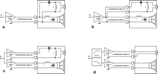
The most common method of wiring between an amplifier and a multi-way loudspeaker is to use a single cable, as shown in Figure 1.2a. The passive crossover networks shown are the simplest possible, and real passive crossovers will very likely have more components.
In bi-wiring (or tri-wiring, or “multi-cabling”) only one amplifier is used, but separate cables run from it to separate sections of a passive crossover that is mounted as usual inside the loudspeaker enclosure; this is illustrated in Figure 1.2b. Bi-wiring requires individual access to the passive crossover sections for the LF unit and tweeter, which is arranged for by having two sets of terminals on the rear of the loudspeaker connected together with shorting links that can be easily removed.
Arranging things for tri-wiring is a little more expensive and difficult, as it requires six terminals and four shorting links, plus the facility of connecting two shorting links to one terminal in a tidy manner. This is probably why loudspeakers with three drive units are more often connected for bi-wiring rather than tri-wiring. Normally the tweeter and mid drive units are connected to one pair of terminals and the bass drive unit to the other. There is also the point that if your taste runs to expensive loudspeaker cables of undefined superiority, having three sets of them is significantly more costly than two.
The question is, just what is gained by bi-wiring? The hard fact is: not much. Its enthusiasts usually claim that separating the high and low frequencies into different cables prevents “intermodulation” of some sort in the cabling. I must point out at once that even the cheapest copper cable is absolutely linear and can generate no distortion whatsoever, even when passing heavy currents. The same absolutely linearity is shown at the smallest signal levels that can be measured. [6] From time to time some of our less bright audio commentators speculate in the vaguest of terms that a metallic conductor is actually some sort of swamp of “micro-diodes”, and that non-linearity might just conceivably be found if the test signal levels were made low enough. This is categorically untrue and quite impossible with it. The physics of conduction in metals has been completely understood for a long time, and there simply is no threshold effect for metallic conduction. The only way that a cabling system can introduce non-linear distortion is if the connectors are defective, which in this context pretty much means either that the contacts are corroded or the connector is about to fall apart altogether and is barely making physical contact.
Actually, a lot of audiophiles are much less definite about the advantages of bi-wiring. They tend to say something pitifully vaporous like: “If only one pair of conductors delivers the whole signal, there is a danger that the bass frequencies can affect the transmission of the more delicate and subtle treble frequencies.” Affect the transmission? Exactly how, pray? And how much danger is there? Not much? Immediate extreme peril? Danger, Will Robinson!
Where bi-wiring can be of use is in minimising the interaction of loudspeaker impedance variations with cable resistances. Let’s suppose that the combination of LF crossover and bass drive unit has a dip in its impedance (the drive unit alone cannot show an impedance lower than its voice coil resistance): this dip will cause a greater voltage drop across the cable resistance, giving a dip in driver output that would not have existed if the cable (and the amplifier) had zero resistance. If we suppose again, and this is a bit more of a stretch, that impedance dips in the HF and LF impedance might overlap, then applying them to separate cables will reduce the level variations. However, the same effect could be got by doubling up a non-bi-wired loudspeaker cable, as this would halve its resistance.
Bi-wiring has a certain enduring appeal because it enables the experimenter to feel he has done something sophisticated to his system but requires little effort and relatively little cost (though this of course depends on how much you think you need to pay for acceptable loudspeaker cables), and the chances of anything going wrong are minimal. This is not of course the case if you start delving about inside a power amplifier.
Bi-amping means a separate amplifier for each crossover section. This almost always implies the use of an active crossover to split the audio spectrum and feed different sections to different amplifiers. Occasionally, however, you hear advocated what might be called full-range multi-amplification. This is shown in Figure 1.2c, where two power amplifiers are fed with identical signals and drive the passive crossover sections separately. This is an expensive way to gain relatively small advantages. The loading on each amplifier will be less, and you might get some of the advantages of bi-amping, such as less stress on each amplifier and reduced intermodulation of LF and HF signals in the amplifiers. The advantage of the latter should be negligible with well-designed solid-state amplifiers, but I suppose there are valve amplifiers to consider. There is also the possibility of using a smaller power amplifier for the HF path. In general, however, this approach combines most of the disadvantages of passive crossovers with the extra cost of active crossovers.
Figure 1.2d shows standard bi-amping, with two power amplifiers fed with the appropriate frequency bands by an active crossover, the passive crossover no longer being present. This is the approach dealt with in this book.
Loudspeaker Cables
It would be somewhat off-topic to go into a lot more detail about loudspeaker cable design, but this might be a good place to point out that there is absolutely nothing magical or mysterious about it. My findings are that, looking at the amplifier-cable-loudspeaker system as a whole, the amplifier and cable impedances have the following effects:
- Frequency response variation due to the cable resistance forming the upper arm of a potential divider with the loudspeaker load as the lower arm. The effect of the resistive component from the amplifier output impedance is usually negligible with a solid-state design, but this is unlikely to be the case for valve amplifiers. This is at least potentially audible; thick cables will minimise the total resistance. It is not a good reason for using anything other than ordinary copper cable.
- A high-frequency roll-off due to the cable inductance forming an LR lowpass filter with the loudspeaker load. The amplifier’s series output inductor (almost always present to give stability with capacitive loads) adds directly to this to make up the total series inductance. The shunt-capacitance of any normal speaker cable is trivially small and can have no significant effect on frequency response or anything else.
The main factors in speaker cable selection are therefore series resistance and inductance. If these parameters are less than 100 mΩ for the round-trip resistance and less than 3 μH for the total inductance, any effects will be imperceptible. [7] These conditions can be met by standard 13-Amp mains cable (I’m not quite sure how the equivalent cable is labelled in the USA). This cable has three conductors (live, neutral, and earth) each of 1.25 sq mm cross-section, made up of 40 x 0.2 mm strands. Using just two of the three conductors, a 100 mΩ round-trip resistance allows 3.7 metres of cable. The lowest cable resistance is obtained if all three conductors are used, normally by paralleling the neutral and earth conductor on the cold (grounded) side of the cable; the maximum length for 100 mΩ is now 5.0 metres, which should do for most of us. This three-conductor method does give what I suppose you might call an “asymmetric” cable, which could offend some delicate sensibilities, but I can assure you that it works very nicely.
The loudspeaker cables that I have in daily use are indeed made of such 13-Amp mains cable, bought from an ordinary hardware shop nearly 40 years ago. Should a passing audiophile query the propriety of using such humble cabling, I usually tell them that with so much passage of time in regular use, the electrons have been thoroughly shaken loose and move about with the greatest possible freedom. I do hope nobody reading this book is going to take that seriously.
The Advantages and Disadvantages of Active Crossovers
Here I have tried to put down all the advantages and disadvantages of the active crossover approach. Some of them may not be very comprehensible until you have read the relevant chapter of this book. My initial plan was to attempt to put them in order of importance, but this is not an easy thing to do. The order here is therefore to some extent subjective, if I may use the term …
The Advantages of Active Crossovers
The advantages of active crossovers are:
- The over-riding advantage of an active crossover is it offers ultimate freedom of design, as virtually any frequency or phase response that can be imagined can be used. The filter slopes of the crossover can be made as steep as required without using large numbers of big and relatively expensive components. Any increase in passive crossover complexity means a significant increase in cost.
- The design of passive crossovers is restricted by the need to keep the loading on the power amplifier within reasonable limits. With an active crossover, correction of the response for each driver is much simpler, as it can be undertaken without having to worry about the combined load becoming too low in impedance for the average amplifier.
- The design of passive crossovers is further complicated by the need to keep the power losses in the crossover within reasonable limits. The losses in the resistors and in the inductors (because of their inevitable series resistance) of a passive crossover, especially a complex design employing high-order filters or time-delay compensation, can be very serious. In a big sound-reinforcement system the losses would be measured in tens of kilowatts. Not only does this seriously degrade the power efficiency of the overall system by wasting power that could be better applied to the drive units, but it also means that the crossover components have to be able to dissipate a significant amount of heat and are correspondingly big, heavy, and expensive. It is far better to do the processing at the small-signal level; the power used by even a sophisticated active crossover is trivial.
- If one of the power amplifiers is driven into clipping, that clipping is confined to its own band. Clipping is usually less audible in the bass, so long as there is no intermodulation with high frequencies. It has been stated that an active crossover system can be run 4 dB louder for the same subjective impairment. This is equivalent to more than twice the power but less than twice the perceived volume, which would require a 10 dB increase in sound pressure level SPL.
- Delays can be added to compensate for differing acoustic centres for the drive units quite easily. Passive delay lines can be built but are prodigal in their use of expensive, lossy, and potentially non-linear inductors, and as a result have high overall losses.
- Tweeters and mid drive units can have resonances outside their normal operating range, which are not well suppressed by a passive crossover because it does not put a very low source impedance across the voice coil. The presence of a series capacitor can greatly reduce the damping of the main resonance, [8] and it is also possible for a series capacitor to resonate with the tweeter voice coil inductance, [9] causing an unwanted rise in level above 10 kHz or thereabouts.
- Drivers of very different sensitivities can be used, if they happen to have the best characteristics for the job, without the need for large power-wasting resistances or expensive and potentially non-linear transformers or auto-transformers. If level controls for the drive units are required, these are very straightforward to implement in an infinitely variable fashion with variable resistors. When passive crossovers are fitted with level controls (typically for the mid unit or tweeter, or both) these have to use tapped auto-transformers or resistor chains, because the power levels are too high for variable resistors, and so control is only possible in discrete steps.
- The distortion of the drive unit itself may be reduced by direct connection to a low-impedance amplifier output. [10] It is generally agreed that the current drawn by a moving-coil drive unit may be significantly non-linear, so if it is taken from a non-zero impedance, the voltage applied to the drive unit will also be distorted. This may be related to out-of-band tweeter resonance; Jean-Claude Gaertner states that tweeters can have increased distortion below 1 kHz. [11] I do not know for sure, but I very strongly suspect that when drive units are being developed they are driven from amplifiers with effectively zero output impedance and that linearity is optimised under this condition. Any other approach would mean guessing at the source impedance, which, given the number of ways in which it could vary, would be a quite hopeless exercise.
- With modern opamps and suitable design techniques, an active crossover can be essentially distortion free, though care must be taken with the selection of capacitors in the filters. It will not however be noise-free, though the noise levels can be made very low indeed by the use of appropriate techniques; these are described later in this book.
A passive crossover contains inductors, which if ferrite or iron-cored will introduce distortion. It also contains capacitors, often in the form of non-polar electrolytics, which are not noted for their linearity or the stability of their value over time. I haven’t been able to find any published data on either of these problems. Capacitor linearity is very definitely an issue because they are being used in filters and therefore have significant voltage across them. It is possible for capacitor distortion to occur in active crossovers too, but the signal voltages are much lower and one can expect the amount of distortion generated to be much less. See Chapter 15, where using the worst sort of capacitor increases the distortion from 0.0005% to 0.005%, with a signal level of 10 Vrms. In contrast, the distortion from a passive crossover can easily exceed 1%.
- With the rise of AV there is more experience in making multi-channel amplifiers economically. The separate-module-for-each-channel approach, where each module has a small toroid mounted right up at one end, while the input circuitry is at the other, is more expensive to manufacture but can give an excellent hum and crosstalk performance. The main alternative is the huddle-around-the-big-central-toroid approach, which has some serious and intractable hum issues.
- If a protection system is fitted that is intended to guard the drive units against excessive levels, then it can be closely tailored for each drive unit.
- Voice coil heating will increase the resistance of the wire in its windings, reducing the output. This is known as thermal compression. It also increases the impedance of a drive unit, and if it is part of a complex passive crossover, the interaction can be such that there are much greater effects on the response than that of thermal compression alone. In one set of tests conducted by Phil Ward, [12] the voice coil temperatures of four different loudspeakers showed a maximum of 195°C and a rise in resistance of 176%. That sort of variation has got to cause interaction with almost any sort of passive crossover.
- It has been proposed that active crossovers can allow the modelling of voice coil heating by calculations based on signal level, frequency, and known thermal time-constants. Thus the effects of thermal compression (the reduction in output as the voice coil resistance rises with temperature) could be compensated for. It does however imply relatively complex computation that would be better carried out by digital processing rather than in analogue circuitry. There would have to be A to D conversion of the signal and perhaps D to A conversion of the control parameters, even if the actual crossover function was kept in the analogue domain. Controlling the active crossover parameters with analogue switches or VCAs without compromising signal quality is going to be hard to do. Modern volume control chips have excellent linearity, but they are not really adapted to general control, and using a lot of them would be rather expensive. If you are undertaking this sort of complex stuff then it’s probably going to be best to do all the processing in the digital domain.
Clearly this plan can only work if the crossover is programmed with the thermal parameters for a given loudspeaker and its set of drive units; this information would have to be provided by the loudspeaker manufacturers, and once again we see the need for the active crossover to be matched to the loudspeaker.
- Drive unit production tolerances can be trimmed out. It has been said that changes in driver characteristics due to aging can also be trimmed out, but since aging is not likely to be an absolutely predictable process, this would ideally require some sort of periodic acoustic testing. For a reference loudspeaker in a laboratory or monitors in a recording studio this is entirely practical, but it is less so in the home environment because of the need for an accurate measuring microphone, or, more likely, one whose response deviations are sufficiently predictable for them to be allowed for. Extra electronics are of course required to implement the testing procedure.
- The active filter crossover components will have stable values. The inductors in a passive crossover should be stable (though I suppose turns could shift under heavy vibration), but the non-polar electrolytic capacitors that are often used have a bad reputation for shifting value over time. The stability of these components has improved in recent years, but it is still a cause for concern. It has been stated that electrolytics in high-end passive crossovers should be regarded as having a lifetime of no more than ten years. [13] Plastic film crossover capacitors such as polypropylene show better stability but are very expensive. A fashion has grown up recently for bypassing big passive crossover capacitors with smaller ones—whether this has any beneficial effects is very questionable indeed.
- The active filter crossover components will not change in the short-term due to internal heating. In a passive crossover the capacitors will have large voltages across them and large currents through them; dielectric losses and ohmic losses in the ESR (equivalent series resistance) may cause these capacitors to heat up with sustained high power and change in value. Non-polar electrolytic capacitors (basically two ordinary electrolytics back-to-back) are considered particularly susceptible to this effect because their relatively small size for a given capacitance-voltage product means they have less area to dissipate heat, and so the temperature rise will be greater.
- The relatively small capacitors used in active crossover filters can be economically chosen to be types that do not exhibit non-linear distortion—polystyrene and polypropylene capacitors have this useful property. Non-polar electrolytic capacitors when used in passive crossovers are known to generate relatively large amounts of distortion.
- No inductors are required in active crossover circuitry (apart perhaps for a few small ones at inputs and outputs for EMC filtering). Inductors are notorious for being awkward and expensive. If they have ferromagnetic cores they are heavy and generate large amounts of non-linear distortion. If they are air-cored distortion is not a problem, but many more turns of copper wire are needed to get the same inductance, and the result is a bulky and expensive component. Martin Colloms has stated [14] that if an inadequate ferromagnetic core is pushed into saturation by a large transient, the resulting sudden drop in inductance can cause a drastic drop in the impedance seen at the loudspeaker terminals, and this sort of thing does not make life easier for power amplifiers.
- Passive crossovers typically use a number of inductors, and it may be difficult to mount these so there is no magnetic coupling between them; unwanted coupling is likely to lead to frequency response irregularities. (It should be said that some types of passive crossover use transformers or auto-transformers, where the coupling is of course entirely deliberate.)
- When a passive crossover is designed, it is absolutely not permissible to treat a drive unit as if its impedance was simply that of an 8 Ω resistor. The peaky impedance rise at resonance and the gentler rise at HF due to the voice coil inductance have to be taken into account to get even halfway acceptable results. This naturally complicates the filter design process considerably, and one way of dealing with this is to attempt to compensate for these impedance variations by placing across the drive unit terminals a series-resonant LCR circuit (to cancel the resonance peak) and an RC Zobel network (to cancel the voice coil inductance rise). [10] This is often called “conjugate impedance compensation”, and while it may make the crossover design easier, it means there are at least five more components associated with just one drive unit, and they all have to be big enough to cope with large signals. There may also be changes in impedance due to changes in acoustic loading across the drive unit’s passband. In an active crossover system the drive unit is simply connected directly to its power amplifier, and assuming that amplifier has an adequate ability to drive reactive loads, the details of the drive unit impedance curve can be ignored. Determined use of conjugate impedance compensation (also called “conjugate loading”) can turn a peaky but essentially 8 Ω impedance plot into a more or less flat 4 Ω plot at the terminals. In my view, artificially reducing a loudspeaker’s impedance to make its plot flatter is a poor idea, as all amplifiers, so far as I know without exception, give more distortion with heavier loading.
- The presence of an active crossover in the system makes it easy to add bass-end equalisation of the loudspeaker; this is distinct from equalising individual drive units. An equaliser circuit is added which provides a carefully controlled amount of bass boost to counteract the natural roll-off of the bass drive unit in conjunction with its enclosure, thus extending the level bass response to lower frequencies. This sort of thing always has to be approached with care, as too much equalisation will lead to excessive drive unit displacements and permanent damage. This is a particular problem with ported enclosures that put no loading on the drive unit cone at low frequencies.
- An active crossover system also opens up the possibility of motional feedback, where the position, velocity, etc of the bass drive unit cone are monitored by an accelerometer or another method, and the information is used to correct frequency response irregularities and non-linear distortion. This is obviously more practical where the crossover and power amplifiers are built into the loudspeaker enclosure. Motional feedback is dealt with in more detail in Chapter 19, but it may be remarked in passing that while it sounds like a first-class idea, it has never achieved much success in the marketplace.
That is a pretty formidable list of real advantages for active crossovers. There are also some claimed advantages that are pretty much bogus, and to be fair we had better have a quick look at these before we move on:
Some Illusory Advantages of Active Crossovers
- A commonly quoted “advantage” is that there is less intermodulation distortion in the power amplifiers because each one handles a restricted frequency range. This may once have been a significant issue, but nowadays designing highly linear power amplifiers is not hard when you know what pitfalls to avoid. I have demonstrated this many times. [15] I suppose this might well be a valid advantage if you insist on using valve amplifiers, which have generally poor linearity, at its worst at low frequencies due to the well-known limitations of output transformers.
- Similarly, it has been claimed that the danger of slew rate limiting is much reduced in the more powerful LF and MF power amplifiers, as they do not handle high frequencies. This is a specious argument, as there is no difficulty whatsoever in designing a power amplifier that has a faster slew rate than could ever conceivably be needed for an audio signal. [16]
- It is sometimes stated that an active crossover system results in simpler loading for each power amplifier, as it is connected to only one drive unit. This is true, as regards human understanding of what the impedance curves look like—it is often difficult to see what causes the impedance ups and downs of a complex passive crossover, whereas for a single moving-coil drive unit the effects of the resonance, the voice coil resistance, and the voice coil inductance are all readily identifiable. However, amplifiers are not sentient, and no amount of anthropomorphic thinking will make them so. An impedance curve that is hard to understand, with a cross-section like the Pyrenees, is not necessarily hard to drive. What puts most stress on a power amplifier are impedance dips and high levels of reactance; these increase the peak and average dissipation in the amplifier output devices. It is not a question of the amplifier having to think harder about it, but the amplifier designer may have to.
- Following from the previous point, an amplifier connected to a single moving-coil drive unit sees basically a mixture of resistance and inductance. Purely capacitative loading is not possible, and it has been said that amplifier stability is therefore easier to obtain. In reality, ensuring amplifier stability into capacitive loads is not a significant a problem—you just put the traditional inductor in series with the amplifier—so this is not a big deal. The inductors used have only a few turns and are not expensive. If you are constructing a system where the amplifiers are permanently connected to the drive units—for example, if the amplifiers are built into the loudspeaker enclosure—then there is the possibility of omitting the power amplifier output inductors, as a single drive unit is essentially resistive and inductive, but I’ll say right now that I’ve never tried this.
- It has sometimes been claimed that it is easier or cheaper to design a power amplifier that only has to handle a limited bandwidth. This is not true. It is absolutely straightforward to design a good power amplifier that not only covers the whole audio spectrum but several octaves on either side of it. Likewise a limited bandwidth does not reduce costs much. You could make the capacitor in the power amplifier negative feedback smaller in the MID and HF channels, but that is a matter of a penny or two; if the amplifiers have separate power supplies, then those for the MID and HF could have smaller reservoir capacitors, which might save tens of pennies. It is possible to save a significant amount of money by designing the HF power amplifier for a lower power output, but that is a different matter from the bandwidth issue and is dealt with in Chapter 17 on crossover system design.
- If we are dealing with an integrated crossover/power amplifier/loudspeaker system with everything installed in one enclosure, it is often claimed there is no need to fit short-circuit protection to the amplifiers, as their outputs are not externally accessible, and so money can be saved. This is a dubious approach, because it assumes that voice coils will never fail short-circuit; if one does there could be serious safety issues. It also assumes that there will be no accidents when testing the amplifiers. The cost saving is very small and is not recommended.
It is still of course very necessary to provide all the power amplifiers with effective DC-offset protection, for safety reasons if for no other. This is a special challenge when driving tweeters, as described later. This is a good deal more expensive than short-circuit protection, as it usually requires an output relay for each power amplifier.
The Disadvantages of Active Crossovers
The disadvantages of active crossovers, once again in what I think to be their order of importance, are:
- Much greater electronic complexity. The number of power amplifiers is doubled, or more likely tripled, and quite possibly quadrupled. This could potentially lead to lower reliability, as the failure of any one of the power amplifiers or of the active crossover itself renders the whole system unusable. However, with proper design techniques and the use of adequate safety margins, the failure-rate of a modern solid-state power amplifier or active crossover should be so low that reliability is not an issue.
- As a direct result of the first statement, there is much more hardware to fit into the living room. Not just more electronic boxes, but all the cabling between them. Ways of tackling this issue are considered later in this chapter.
- Also flowing from (1) is the issue of greater cost. The high-frequency amplifiers can be of lower power output than the low-frequency amplifiers, but this definitely does not reduce their cost proportionally. There may be economies of scale to be made by making all the power amplifiers identical, but with the high-frequency ones fed from lower supply voltages. This is perfectly feasible without any compromise on amplifier performance.
Against this must be set the fact that precise, stable, and generally high-quality components for passive crossovers are not cheap, and a top-end passive crossover can easily end up costing more than an active crossover; this does not however take into account the extra power amplifiers.
- The vast majority of active crossover loudspeakers have been built as one unit. A mono active crossover and the two or three power amplifiers required are put inside into the loudspeaker enclosure. While this makes a very convenient package, which requires only a mains lead to each loudspeaker as extra wiring, it has a deadly disadvantage. The simple truth is that people want to be able to choose their own power amplifiers. Not everybody is prepared to believe that a company that specialises in loudspeakers would be able to come up with a good power amplifier, and it is entirely understandable that people prefer to buy each audio component from specialists in the relevant field.
- The active crossover must be matched to the loudspeaker and cannot be bought off the shelf. Many speakers allow for bi-wiring, but this still leaves the passive crossover components in place. Few, if any, loudspeakers allow direct access to the drive units without some serious dismantling, and so any domestic system must be either home-built, or custom-built, with a commensurately high cost.
- Tweeters, and to a lesser extent, midrange drive units are much more exposed to amplifier DC-offset faults. When they are connected to an amplifier via a passive crossover, there will be at least one capacitor between the amplifier and the voice coil. This will be of modest size, as it is not intended to pass low frequencies, and so provides very good protection for tweeters and midrange drive units which do not have the displacement capability or thermal inertia of bass drivers. Tweeters in particular can be destroyed in an instant by a large DC offset. This seems to me a very good, if not irrebuttable, argument for using a low-power amplifier to drive the tweeter in an active crossover system.
Any DC-coupled amplifier connected to a loudspeaker should of course have DC-offset protection, but since such a fault is usually detected by putting the output signal through a lowpass filter with a very low cutoff frequency to remove all the audio and then applying it to a comparator, there is inevitably some delay in its operation; an output muting relay also takes a significant amount of time to open its contacts and break the circuit. If the amplifier driving the tweeter is specialised for the task then it can be given DC protection that reacts more quickly, as its lowpass filter will not need to reject high amplitude bass signals; it can therefore have a higher cutoff frequency and will respond faster.
- There will be a greater power consumption due to quiescent current flowing in more amplifiers. In a solid-state Class-B power amplifier, how much power is involved depends on the details of the output stage design. Class-A amplifiers, built with any technology, uselessly dissipate almost all the power so trustingly fed into them, showing efficiencies of around 1% with musical signals, as opposed to sine wave testing. [17] There is also the power consumption of the active crossover itself, but this is not likely to be significant, even for a very complex analogue active crossover.
- Passive crossovers cannot be radically maladjusted by the user (though some allow vernier adjustments, typically of HF output level). In the sound-reinforcement business there is always the possibility that some passing “expert” may decide to try and use the crossover controls as a sort of equaliser. This is unlikely to be effective and can result in severe damage to loudspeakers. Lockable security covers solve this problem.
- Active crossovers add extra electronics to the signal path which would otherwise not be there and so must be beyond reproach, or at any rate not cause any significant signal degradation. With the intelligent use of either opamp or discrete circuitry this should not be a serious problem.
The Next Step in Hi-Fi
As we have just seen, active crossovers have a long and convincing list of technical advantages. The score is 22 very real advantages and five not-too-convincing advantages, as opposed to nine advantages for passive crossovers. It is generally accepted that active crossover hi-fi systems sound obviously better than their passive crossover counterparts. Any sort of consensus is rare in the wide field of audio, so this is highly significant. I strongly suspect that the widespread adoption of active crossovers, suitably matched to their loudspeakers, would be The Next Big Step in Hi-Fi, and possibly even The Last Big Step possible with current technology.
Nonetheless, it is undeniable that active crossovers, despite their compelling advantages, have made very little headway in the domestic market so far, though they are used in all but the smallest sound-reinforcement systems, and extensively in automotive audio. The big question is how to make active crossover technology more acceptable in the marketplace. The first thing we shall do is look at ways of solving the “too many boxes and wires” problem.
Active Crossover Systems
We will consider the various ways in which an active crossover system can be configured, with an especially hard look at making it acceptable in a domestic environment. Sound-reinforcement systems are a separate issue. One of the significant disincentives to the active crossover approach is the sheer amount of hardware required, in terms of electronic boxes and cables. This can be hard to fit into a minimalist decoration scheme—and indeed often hard to fit into any sort of decoration scheme at all. It is desirable to package the technical functionality as neatly as possible. I am assuming here that a high-quality system is intended, and so 3-way active crossovers will be used.
In terms of cabling and equipment the tidiest setup is undoubtedly achieved with a mono active crossover and its three power amplifiers built into each loudspeaker enclosure, but it is vital to realise that this is not an acceptable approach for people who take their power amplifiers at all seriously.

Figure 1.3 shows an active crossover system using six separate monobloc power amplifiers. This could be configured with all six amplifiers in one location, in which case putting them all near one of the loudspeakers reduces the length of at least one set of loudspeaker cables to a minimum. The amplifiers may be all of the same type, but all that is really required of them is that they have the same gain. Even if we have six nominally identical amplifiers made at the same time by the same manufacturer, somewhere in each amplifier will be at least two gain-setting resistors, each with a tolerance; nonetheless, in a competent design the variation should be comfortably less than variations in the drive units.
Alternatively, three of the power amplifiers could be placed adjacent to each loudspeaker, considerably shortening the total length of what might be expensive loudspeaker cable, as three of the connections are now very short. Three of the line-level cables to the power amplifiers naturally become correspondingly longer, but since their resistance is of much less importance than that of the loudspeaker cables, this is overall a good thing. The increased resistance of long line cables makes the link more susceptible to voltages induced by currents flowing through the ground connection, but I think it is fair to assume that a hi-fi system with active crossovers would use balanced connections to cancel such noise. Ultimately the placing of the various parts of the system is going to be influenced by furniture arrangement and the availability of handy (and hopefully well-ventilated) cupboards in which to stash the boxes.
Adding it up, a system configured in this way consists of seven electronic boxes, (not including the preamplifier) eight line-level cables and six loudspeaker cables. If the connection from the preamp to the crossover is a 2-way cable (i.e. two parallel cables joined together along their length), that is reduced to seven boxes, seven line cables, and six loudspeaker cables, which is hardly a great improvement.
However, it must be said that there are excellent technical reasons for using 2-way cables when you can. Their construction keeps the grounds for the two links physically close together and prevents them forming a loop that could pick up magnetic fields which would induce current flow; this current would cause voltage drops in the ground resistance and degrade the signal. The use of balanced connections greatly reduces the effects of ground currents, but it is of course much sounder to prevent the currents arising in the first place.
In Figure 1.4, the system is configured with three stereo power amplifiers. This has the advantage that stereo amplifiers are the most common sort and give the greatest choice. The ones used here are assumed to be identical; if a lower-power stereo amplifier is chosen to drive the tweeters, then Figure 1.4 would need to have its connections rearranged. Figure 1.4 uses five electronic boxes, eight line cables, and six loudspeaker cables. Using 2-way cables between the preamplifier and crossover and also to the power amplifiers simplifies this to five boxes, four line cables, and six loudspeaker cables. There are always going to be six loudspeaker cables.
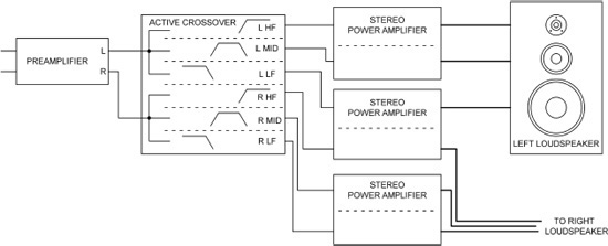
Figure 1.5 shows a variation on this approach which puts one of the stereo amplifiers adjacent to the right loudspeaker instead of piling them all up on the left side. This cuts down the total length of loudspeaker cable required, but there is still a long run from one amplifier on the left to the right loudspeaker on the other side of the room.
The opinion is held in some quarters that very high degrees of isolation between left and right channels is essential to obtain an optimal stereo image. This is wholly untrue, but audio is not a field in which rational argument can be relied upon to convince everybody. The configuration of Figure 1.5 could be criticised on the grounds that left and right channels pass through one stereo power amplifier, and this might compromise the crosstalk figures. It is not actually harder to get a good crosstalk performance from a stereo power amplifier than from a stereo preamplifier; in fact it is usually easier because the preamplifier has more complex signal routing for source selection and the like. Nonetheless it is only fair to point out that there might be objections to the 3x stereo amplifier arrangement because however it is configured, at least one amplifier will have to handle both right and left signals.
We will now take a radical step and assume the ready availability of three-channel power amplifiers.
Multi-channel power amplifiers at a reasonable cost have been available for surround-sound systems for many years, to deal with 5:1 formats and so on. The last multi-channel power amplifier I designed (The TAG 100x5R:10) could be configured for ten channels of 80 W/8 Ω each. A three-channel power amplifier of high quality presents absolutely no new technical challenges at all.
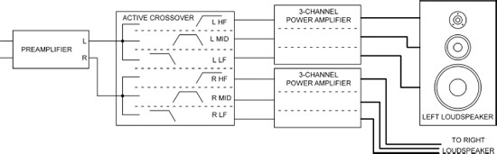
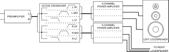
As you can see from Figure 1.6, using two three-channel power amplifiers simplifies things considerably. There are now four electronic boxes, eight line cables, and six loudspeaker cables. Using a 2-way cable from preamp to crossover and 3-way cables between the crossover and amplifiers is well worthwhile and reduces the parts count to four boxes, three line cables, and six loudspeaker cables. This important configuration is shown in Figure 1.7. One of the three-channel power amplifiers could be sited over by the right loudspeaker, and this is much to be preferred as it minimises total loudspeaker cable length. I think it is fairly clear that this is the best way to configure things, with the least number of separate parts and the possibility of keeping the loudspeaker cables very short indeed if each power amplifier is sited right behind its loudspeaker.

The only real difficulty is those three-channel power amplifiers. Some do exist, evidently intended for multi-channel AV use rather than in active crossover systems; two current examples are the Classé CA-3200 three-channel power amplifier [18] and the Teac A-L700P 3-Channel Amplifier. There appear, however to be no three-channel amplifiers specifically designed for our application here. Such an amplifier would be able to economise on its total power output by having a big output for the LF driver, a medium output for the mid drive unit, and a smaller output again for the tweeter. The downside to that plan is that it would be less versatile than a three-channel amplifier with equal outputs, which could be pressed into stereo or multi-channel service if required.
3-way cables should present no problems; in the UK, the widespread Maplin chain sells four-way audio line cables with individually lap-screened cores at a very reasonable price. Individual screened cores are of course highly desirable to prevent capacitive crosstalk.
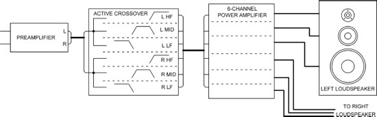
Figure 1.8: Active crossover system using a single six-channel power amplifier and multi-way cables.
To take things to their logical conclusion, we can use a six-channel power amplifier. These are used extensively in AV applications so are not hard to obtain. If we assume the use of multi-way cables from the start, we get Figure 1.8. This cuts down the separate pieces of hardware to the minimum, giving three electronic boxes, two line cables, and the usual six loudspeaker cables. Unfortunately this configuration brings back the need for long and possibly expensive loudspeaker cables to drive the right loudspeaker, and it also raises again the question of left-right crosstalk in the power amplifier.
In my view the configuration using two three-channel amplifiers is clearly the best approach. There is one more box but the loudspeaker cables can be of minimal length.
Matching Crossovers and Loudspeakers
Having looked at the best way to package and configure an active crossover system, there are some other issues to deal with. In the sound-reinforcement business, active crossovers are sold with wide-ranging control over crossover frequencies, time-delay compensation, and so on. This is feasible in a situation where skilled operators set up the system. In a hi-fi situation it is more common to have fixed crossover parameters that are carefully matched to the loudspeaker characteristics. These parameters include not only crossover frequencies and delays but also things like drive unit frequency response equalisation, diffraction compensation equalisation, and so on. The crossover has to be set up for one model of loudspeaker only. This is fine if the crossover and amplifiers are built into the loudspeaker, but as we have seen, this is not going to work for potential customers who want to choose their own power amplifiers, and that is most of them.
The solution to this problem is to sell active crossovers and loudspeakers as a matched package, but leave the power amplifiers to be bought separately. All that would be required of the amplifiers is that they should all have the same gain. This is nothing new; THX-spec amplifiers all have a gain of +29 dB for an unbalanced input. For the higher reaches of the high end, each active crossover unit could be individually calibrated by acoustic testing to match each loudspeaker with its drive units at the factory, authoritatively solving the problem of variation in drive unit parameters. The loudspeakers and crossover would then be tied together by their serial numbers. Obviously it would be essential to not swap over the Left and Right channels at any point. The calibration could be done by plugging in resistors until the optimal result is obtained and then soldering them in permanently. This kind of hand tuning would not of course be cheap, but with the right measuring gear and an intelligent algorithm for adjusting the various crossover parameters, I am sure it could be done at a price some folk would be prepared to pay.
What it would not do is compensate for drift in drive unit parameters over time. This could only be addressed by regular recalibration, which would be unpopular with most people if it involved sending the crossover and loudspeakers back to the factory. And handing over some more money, no doubt.
For this scheme it would be necessary to construct loudspeakers so that direct access could be gained to the drive units, optionally bypassing the internal passive crossover, if one is fitted at all. Providing facilities for bi-wiring on the back of a loudspeaker is straightforward; you just put four terminals on the back and add a pair of shorting links that can be easily removed. Tri-wiring is a little more difficult but still thoroughly doable. Bypassing a passive crossover is however more complex, as it is necessary to disconnect it not only from the input terminals but also from two, three, or possibly four drive units.
A Modest Proposal: Popularising Active Crossovers
Let us suppose that it becomes accepted practice to sell crossovers and speakers as a package, but the amplifiers are bought separately. As we have just seen the best and neatest way to configure the complexities of a 3-way active crossover system is to use three- or six-channel power amplifiers, and one might hope that a market for these would develop. One wonders if there might be some sort of psychological resistance to buying two parts of the audio chain with a gap (the power amplifier) between them. We can, I think, confidently predict that some enthusiasts would favour different makes of power amplifier for the LF, MID, and HF channels. There would be much room for entertaining debate if you like that sort of thing. We might even speculate that third-party active crossovers might be marketed to replace those from the speaker manufacturer.
We also saw that it is highly desirable to use multi-way cables between the active crossover and the power amplifiers, for tidiness as well as the best technical performance. A market could emerge for 3-way or six-way leads. Ideally each audio line should be individually screened to prevent capacitive crosstalk between them, especially on long cable runs, but this puts the cost of the cable up substantially. Conventional line outputs have a series resistor in the output to ensure stability when faced with cable capacitance from signal to ground, resulting in a typical output impedance of 50–100 Ω. This is enough to allow the capacitance between adjacent and unshielded signal conductors to significantly degrade the crosstalk performance. A most effective solution to this problem is the use of so-called Zero-impedance line outputs on the crossover. This technology typically achieves an output impedance of a fraction of an ohm and can reduce crosstalk by 40 dB or more; it is equally stable into long cable runs, and the extra cost is trivial. Zero-impedance outputs are fully described in Chapter 21 on line output stages.
An unbalanced six-way interconnection uses six signal feeds and at least one ground wire, and so requires at least seven pins in the connector used.
Since an active crossover system is expected to reach high levels of quality, the use of balanced interconnections needs examination. The hot and cold signals from each channel can be wrapped by a single grounded screen, but ideally there would be separate assemblies of this sort for each channel, which makes for rather non-standard cable. Conventional balanced operation naturally increases the number of contacts on the connectors used to at least (6 × 2) + 1 = 13, though multiple ground connections would be good, not only to reduce voltage drops due to ground currents but also to avoid alarming the superstitious end of the audio market.
This assumes that the outputs are truly balanced, in that there are two outputs in anti-phase. This gives a handy 6 dB increase in level over the link, which is very useful in coping not only with noise on the link itself, but also relatively noisy balanced input amplifiers; see Chapter 20. If however we drop the requirement for anti-phase outputs, then we could have a quasi-balanced cable with six signal feeds, one cold line to sense the source-end ground, and one ground wire. The single cold line would be distributed to the cold inputs of six balanced input amplifiers at the receiving (power amplifier) end. The danger is, of course, that people would condemn it as “not a real balanced connection”, though it would almost certainly give an equally good performance as regards common-mode rejection. This plan would require a minimum of eight pins in the connector.
Multi-Way Connectors
A multi-way cable requires multi-way connectors. It would be nice if active crossovers became so popular that a committee designed a special connector for us (like the HDMI connector, for example), but realistically that isn’t likely to happen soon. It is therefore worth looking at what existing connectors are capable of meeting our needs. What we must strive to avoid is a connector configuration already in common use, because in the real world people are prone to plug stuff into any socket that will physically accept it.
XLR connectors have the benefit of being fairly familiar, but they only go up to seven pins. [19] This is fine for 3-way balanced use, but only allows unbalanced six-way operation (six audio feeds plus a common ground). Since we are dealing with higher-end systems, it seems inappropriate to rule out balanced operation.
The familiar standard DIN connectors have a 13.2 mm diameter metal body and go up to eight pins, [20] so we can have fully balanced 3-way operation or six-way quasi-balanced operation, but not fully balanced six-way usage. These connectors have some unfortunate associations with the low-quality DINs in the past, but today reliable high-quality versions are freely available and are used for MIDI links and stage lighting control. They are not popular with those who have to solder cables into them, but then this is probably true of any small multi-way connector.
The smaller Mini-DIN connectors [21] are 9.5 mm in diameter and officially come in seven patterns, with the number of pins from three to nine, though there are at least two non-standard ten-pin versions which are not approved by the Deutsches Institut für Normung (DIN), the German standards body. Once more we can have fully balanced 3-way operation, or six-way quasi-balanced operation, but not a fully balanced six-way mode. Mini-DINs are sometimes called “video camera connectors” though they have in fact been used for a very wide variety of uses, including computer power supplies, so there is a definite element of risk there.
The nine-way D-type connector [22] is inexpensive and offers screw retention, but it is hard to argue that it has anything of a high-end audio air about it. It is also likely to get plugged into the wrong place, whereas standard-format connectors like XLRs or DINs with an unusually large number of pins are much safer. Once more we can have fully balanced 3-way operation, or six-way quasi-balanced operation, but not a fully balanced six-way mode.
The 15-way D-type connector has the same problem of lack of glamour as the nine-way, but it is the only easily-sourced connector which will allow fully balanced six-way operation. The two spare ways can be usefully pressed into service as extra ground connections, or used for control functions such as 12 V trigger to activate amplifiers.
There are various proprietary connector systems; for example the eight-way Neutricon by Neutrik is a robust circular metal connector. [23] It is stocked by Farnell so is easy to source. Neutrik also make the 12-way miniCON. [24]
Subjectivism
As I warned you in the preface, this book has no truck with faith-based audio. There is no discussion of oxygen-free copper, signal cables that only work one way, magic capacitors hand-rolled on the thighs of Burmese virgins under a full moon, or loudspeaker cables that cost more than a decent car. Valve technology is ignored because it is inefficient and obsolete and, despite much ill-informed special pleading, absolutely has no magical redeeming features. You will find here no gas-fired pentodes, nor superheated triodes fed with the best Welsh steam coal and still bespattered with the mud of the Somme. It would of course be possible to design a complex active crossover using valves, but even if you accepted mediocre performance as regards noise and distortion, the result would be very expensive, very hot, and very heavy.
You will, I think, find enough real and intriguing intellectual challenges in crossover design to make it unnecessary to seek out non-existent ones.
References
[1]www.talkbass.com/wiki/index.php/Driver_diameter_&_pistonic_beaming_frequencies
[2]Self, Douglas “Audio Power Amplifier Design” Sixth Edn, Newnes, 2013, pp. 370–371, ISBN: 978-0-240-52613-3, Chapter 14
[3]https://en.wikipedia.org/wiki/Dolby_noise-reduction_system; Accessed December 2016
[4]http://djtechtools.com/2011/12/11/an-introduction-to-mixing-with-dj-isolator-mixers/; Accessed December 2016
[5]http://formula-sound.co.uk/1ru-solutions/fsm-3-1ru-isolator/; Accessed December 2016
[6]Self, Douglas “Ultra-Low-Noise Amplifiers & Granularity Distortion” JAES, November 1987, pp. 907–915
[7]Self, Douglas “Audio Power Amplifier Design” Sixth Edn, Newnes, 2013, pp. 370–371, ISBN: 978-0-240-52613-3 (cable effects)
[8]Colloms, Martin, “High Performance Loudspeakers” Third Edn, Pentech Press, 1985, p. 174, ISBN 0-7273-0806-8
[9]Colloms, Martin, “High Performance Loudspeakers” Third Edn, Pentech Press, 1985, p. 178, ISBN 0-7273-0806-8
[10]Borwick, John (ed.)“Loudspeaker & Headphone Handbook” Second Edn, Focal Press, 1994, p. 234, ISBN 0-240-51371-1
[11]Gaertner, Jean-Claude “Project 21 Part 1” Linear Audio Volume 0, pub J Didden 2010, p. 132 ISBN: 9–789490–919015
[12]Ward, Phil www.soundonsound.com/sos/jul02/articles/monitors2.asp (thermal compression)
[13]Newell, Phillip “Recording Studio Design” Second Edn, Focal Press, p. 511, ISBN: 978-0-240-52086-5
[14]Colloms, Martin “High Performance Loudspeakers” Third Edn, Pentech Press, 1985, ISBN 0-7273-0806-8
[15]Self, Douglas “Audio Power Amplifier Design” Sixth Edn, Newnes, 2013, Chapter 12, ISBN: 978-0-240-52613-3(power amp distortion)
[16]Self, Douglas “Audio Power Amplifier Design” Sixth Edn, Newnes, 2013, Chapter 15, ISBN: 978-0-240-52613-3 (slew-rate limiting)
[17]Self, Douglas “Self On Audio (Audio Power Analysis)”Third Edn, Newnes, 2016, Chapter 41, ISBN: 978-1-138-85445-1 hbk(Class-A efficiency)
[18]Rubinson, Kalmanwww.stereophile.com/solidpoweramps/207classe/(review)
[19]https://en.wikipedia.org/wiki/XLR_connector;Accessed December 2016
[20]https://en.wikipedia.org/wiki/DIN_connector;Accessed December 2016
[21]https://en.wikipedia.org/wiki/Mini-DIN_connector;Accessed December 2016
[22]https://en.wikipedia.org/wiki/D-subminiature;Accessed December 2016
[23]www.neutrik.com/en/industrial/circular-connectors/neutricon/neutricon-connectors/;Accessed December 2016
[24]www.neutrik.com/en/industrial/circular-connectors/minicon/minicon-connectors/;Accessed December 2016