
Chapter 19
Motional Feedback Loudspeakers
Motional Feedback Loudspeakers
The use of motional feedback to improve loudspeaker operation is closely related to active crossover technology. The amplifier is usually physically part of the loudspeaker because it is even more closely coupled than an active crossover system. As described in Chapter 1, you can buy an active crossover and matched loudspeaker from Company A and between them put a power amplifier from Company B; all you have to do is get the gain right. Motional feedback (MFB), on the other hand, depends critically on loudspeaker characteristics not only to work at all but in some cases to avoid catastrophic instability. Only one company (Yamaha) has released stand-alone amplifiers with a motional feedback capability.
Many loudspeaker problems are caused by the fact that a drive unit cone does not follow exactly the voltage driving it but has a life of its own due to cone inertia and suspension non-linearities; this is further complicated by cone break-up modes, where different parts of the cone are moving independently. Negative feedback can work miracles in controlling precisely the output voltage of a power amplifier, and it is a logical step to attempt to gain the same iron control over a drive unit cone by sensing its movement and using that to close a negative feedback loop; this promises both a better frequency response and lower distortion. It is however much more difficult to control a speaker cone with negative feedback than it is a simple output voltage. Motional feedback (MFB) for anything other than a full-range driver unit requires the use of an active crossover, because one amplifier can only control the movement of one drive unit. MFB is typically only applied to the LF unit, as this has the largest excursions, creates the greatest amount of distortion, and is generally further removed from being an infinitely rigid zero-mass piston than the MID and HF units. MFB is also relevant to this book because equalisation of the drive units is often necessary.
Despite this promising prospectus, motional feedback has had little success in the marketplace. The best-known example is the Philips 22RH544 loudspeaker, which derived its motional feedback from a small accelerometer mounted on the dust-cap of the LF unit voice coil. This was made and sold for ten years and was undoubtedly a good product, but it failed to trigger a wave of enthusiasm for MFB.
One of the main challenges of MFB is sensing the motion of the drive unit cone without putting any restraint on its movement. The basic idea is shown in Figure 19.1. There are three basic ways to do this:
- Measure the cone position.
- Measure the cone velocity.
The velocity can be integrated to get the cone position.
- 3. Measure the cone acceleration.
This can be done with a small and light accelerometer. Acceleration can be integrated to get cone velocity and then integrated again to get cone position. The prime example of this is the method used by the Philips 22RH544.
History
As usual, the history of the concept goes back a surprisingly long way. The first reference found was [1] from 1951. See also [2] from 1958 and [3] from 1963. None of these are easy to come by, but a very good early reference that is available is the 1964 Philips Technical Review, [4] which describes the origins of the accelerometer approach.
Feedback of Position
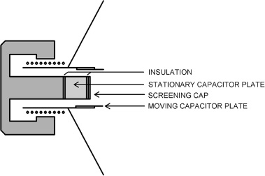
This clearly needs to interfere with cone movement as little as possible; one obvious method that adds very little weight is capacitance sensing. It is not enough simply to fit a conductive dust-cap and place a fixed plate some distance from it; the capacitance is inversely proportional to the distance between the two capacitor plates, and so the position signal will be grossly distorted. An early attempt was by Brodie in 1958, [5] but as far as I can see it does not address the inverse proportionality. We need a linear change of capacitance with cone position. A neat solution was put forward by ServoSpeaker in 2004 [6][7] and is shown in Figure 19.2. The capacitance depends on the degree of overlap of the moving and fixed plates and is to a first approximation linear. A patent application was made in 2004, [8] and the technology was described in Hifi-World in 2008, [9] but as far as I can determine no product got to market, and ServoSpeaker no longer seems to exist as a company.

Ever since I first heard of MFB, it struck me that laser interferometry would be the ideal method; no moving parts added and no extra wires attached to the cone. Laser diodes can’t be expensive, since there’s one in every CD player—how hard can it be? However, I know little of such matters; one person consulted told me that the laser required to get the necessary coherence length would be pretty big—a metre or more long for a frequency stabilised helium-neon laser, which I was told was about the minimum hardware I could get away with. That doesn’t sound too practical; I would be glad to hear if others agree on the possibilities of laser interferometry.
Feedback of Velocity
At first it looks as if this might be easy; a secondary sensing coil is added to the cone primary drive coil and will produce a voltage proportional to its velocity in the magnetic field. The main problem with this approach is transformer coupling between the main voice coil and the sensing coil, which will completely swamp the desired velocity signal. A solution to this which was perhaps clumsy but has a certain no-nonsense appeal was that adopted by Panasonic MF-800 in the early 1960s (see Figure 19.3). [10] A second voice coil and magnet were mounted at the front of the drive unit, much reducing transformer action. On reading the user manual it is claimed that MFB reduces “distortion”, but it is not clear if that refers to frequency response errors or non-linear distortion or both. The main aim is clearly to extend the LF response of the loudspeaker, and switches for controlling this were provided, labelled “Frequency” and “Damping”.
There seems no doubt that this method worked as advertised, though according to the manual some control settings gave bass extension combined with a +6 dB resonance peak, which probably did not sound great. This could be suppressed by increasing the damping setting, but this much reduced the bass extension. There are very few references to this system anywhere, which suggests it was not a marketing success. No pictures of the actual drive units have so far been found.
A more subtle and apparently superior approach is to use the same voice coil for both driving the cone and measuring its velocity. The movement of the coil in the magnetic field generates a voltage signal Vvel proportional to the velocity, but this has to be somehow separated out from the voltage driving the speaker. Figure 19.4 shows one way; a balancing impedance R1, L1 is put in series with the drive unit; typical values are shown. The transformer reads the voltage across this load and subtracts it from the main feedback signal so that the velocity signal is isolated and can be added to the feedback as required. Note that the balancing impedance is made equal to the blocked impedance of the drive unit, which is its impedance when the voice coil is fixed so that it cannot move.
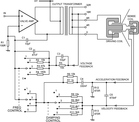
Figure 19.3: Motional feedback of velocity using a separate sense coil and magnet: Panasonic MF-800.
This method has a disadvantage which I don’t think I have ever seen explicitly pointed out; as shown it wastes half of the amplifier power that you trustingly feed into it, dissipating it in the balancing impedance. To make this approach practical the balancing impedance must be scaled so it dissipates a small fraction of the power in the drive unit, by raising the transformer ratio or otherwise modifying the feedback arrangements. See [4] for other versions of this circuit.

A transformer is not a welcome part in a negative feedback loop; it may have its own linearity problems at low frequencies, and HF phase-shifts are likely to cut down the stability margins. Figure 19.5 shows a more up-to-date version, where the required subtraction is performed by opamp A1. The balancing impedance has been scaled down by a factor of seven to demonstrate the process, but the power dissipated in R4 will still be substantial, and further scaling would be desirable. The scaling is embodied in the values of R1, R2, and R3.
This method can also be looked at as making the output impedance of the amplifier negative—it is equal and opposite to the blocked impedance of the drive unit. This should not be confused with current-drive of loudspeakers, where the output impedance is made very high.
This all seems very promising—you can use standard drive units and do the MFB with a few cheap electronic parts. But there are two big problems remaining with voice coil velocity feedback: First, the resistance of a drive unit voice coil changes significantly when it gets hot; a 40% increase is entirely possible with a 100°C temperature rise. This plays mayhem with the impedance balancing, and it would be all too easy to produce a design that became unstable as it heated up, banging the amplifier output against one of the rails. In practice this means that only a small amount of negative feedback can be applied safely.
Second, the uniformity of the magnetic field in which the voice coil moves is imperfect, and this reduces the accuracy of the velocity feedback signal.

Much work has been put into the first issue. Temperature compensation is difficult because the voice coil is a highly inaccessible position in the magnet gap. The only workable technique appears to be the addition of another coil on the former, made of the same grade copper. Depending on the details of construction, this coil will get close to the voice coil temperature. Note this is not a velocity-sensing coil; its proximity to the voice coil means the transformer action would be too strong. Instead the coil is wound non-inductively, so that transformer action is (mostly) prevented, and it responds only to temperature. A difficulty is that you have to put two windings in where but one grew before, and this is likely to require a bigger magnetic gap, leading to lower efficiency.
Variations on this technique were used by Servosound, a Belgian company operating in the early 1970s, and by Yamaha, with their Active Servo Technology (AST). One example is the AST A-90M, a 45 W/6 Ω integrated amplifier. This separate amplifier was matched to different Yamaha loudspeakers by means of a cartridge plugged into the front panel of the amplifier, which controlled both the impedance characteristics and the LF equalisation. Another was the AST-A10 power amplifier (1989), where the loudspeaker current was measured by 0.2 Ω resistors in the return connection. There was also the AST-P2601 professional audio amplifier. All three used the cartridge system, and Yamaha naturally only provided cartridges for their own loudspeakers. I have not been able to discover what happened if you plugged in the wrong cartridge for a given loudspeaker.
Feedback of Acceleration
The best-known example of this technology is the Philips 22RH541 motional feedback loudspeaker, manufactured from 1975 to 1985. [11] It was a 2-way loudspeaker with the HF and LF drive units fed from a passive crossover, with MFB applied only to the 8inch LF drive unit. Figure 19.6 shows a simplified version of the arrangement. A piezo-electric accelerometer with a preamplifier consisting of a JFET and two resistors was mounted inside the LF unit dust-cap (components inside dashed box). The JFET drain current then passed through cascode transistor Q2 to virtual earth amplifier A2.
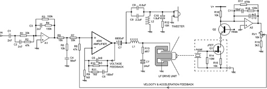
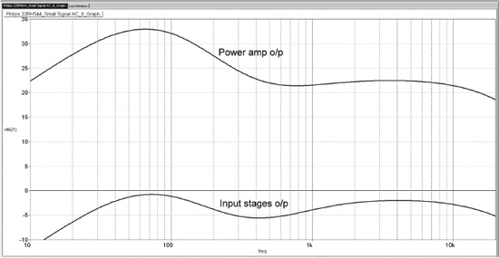
A good deal of equalisation is applied around the input stage A1, as shown by the lower trace in Figure 19.7; three time-constants are employed. Further equalisation is applied by the components in the voltage feedback path of the power amplifier, giving the upper trace in Figure 19.7. The power amplifier is AC-coupled to the drive units via C7, so there is no possibility of them being damaged if the amplifier sticks to one rail. The passive 2nd-order crossover uses C8, C9 and L2 to direct the HF to the tweeter, while L1, R13 and C7 direct the LF to its driver. There is a Zobel network R12, C10 across the tweeter and another Zobel network R13, C7 across the LF unit.
There is no short-circuit protection, but then there is no access to the amplifier output, so it is not going to be short-circuited by the user.
The accelerometer preamp stage was cleverly arranged to work into the common-base stage Q2, so that only two wires to the accelerometer assembly were required. The signal then goes to A2, which implements the lowpass filter and integrator required to produce acceleration and velocity feedback signals. See [4]. The RC network involved contains a 4n3 capacitor; E24 capacitor values are unusual even today, and this suggests some fairly critical adjustment was being performed. There is a preset RV1 that controls the amount of MFB applied; I have been unable to determine exactly what this compensates for, but I suggest probably variations in the LF drive unit compliance. The 22RH541 also contained a significant amount of circuitry to switch the unit out of standby when a signal was applied.
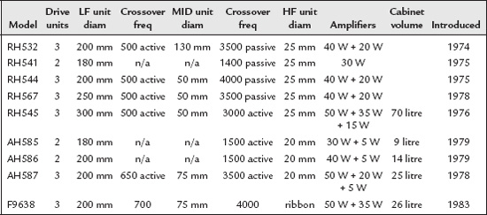
There were eight models in the Philips MFB range. The first to be introduced was the RH532 in 1974, [12] reviewed in Popular Electronics in March 1975. [13] It was a 3-way bookshelf speaker, with very similar technology to the 22RH541 described earlier. A 20 W power amplifier drove the HF and MID units through a 2nd-order passive crossover (at 3.5 kHz) with Zobel networks across the drive units. A separate 40 W power amplifier drove the LF unit, which was the only one with MFB applied. The crossover frequency between the two amplifiers was 500 Hz.
The specifications for the various models are summarised in Table 19.1. All had MFB on the LF unit only. Cabinet volume is not given when I only have the external dimensions to work on, because the internal electronics take up a significant but unknown amount of space. More details on specific models are given later. The schematics are easily found on the Web.
The RH545 was the first MFB model to offer switchable correction filters for “Rear to wall”, “Floor”, and “Side to wall” loudspeaker placement. “Side to wall” used three gyrators to create a −3 dB dip between 55 and 160 Hz, “Rear to wall” used a single gyrator to create a −5 dB dip at 60 Hz, and “Floor” used a single gyrator to create a −5 dB dip at 200 Hz. Each gyrator was made from three discrete transistors; they are not ‘standard’ gyrators, and their detailed operation is quite complex.
The AH586 was a 2-way speaker offering switchable correction filters for “Rear to wall”, “Floor”, and “Side to wall” placement, but the equalisation was simpler. “Rear to wall” used a single gyrator to create a −6 dB dip at 63 Hz, “Floor” used a single gyrator to create a −3.5 dB dip at 125 Hz, and “Side to wall” equalisation used two simple time-constants to create a very gentle 3.5 dB dip around 63 Hz. Thus only two gyrators were used instead of five.
The AH587 was a 3-way speaker. Notably, each of the three drive units had a different impedance. The HF drive unit had a 15 Ω impedance, the MID unit an 8 Ω impedance, and the LF unit a 4 Ω impedance, to suit the signal levels in each frequency range. “Rear to wall”, “Floor”, and “Side to wall” correction options were provided, exactly as for the AH586.
The F9638 was a 3-way speaker using flat-membrane LF and MID drive units, with a ribbon tweeter. It was presumably intended as the next generation of Philips MFB loudspeakers. MFB was only applied on the LF unit. It was introduced in 1983 but does not appear to have been successful, and went out of production in 1986. I think this was the only F-series MFB loudspeaker.
The Philips numbering system is somewhat opaque. For example AH468 and AH483 sound like they might be in the same MFB product series, but actually both were passive crossover loudspeakers.
Slightly off-topic, as this loudspeaker did not use MFB, but still of considerable interest is the Philips DSS930, which used DSP for its active crossover functions and a Class-G amplifier [14] for the LF drive unit.
Since the Philips loudspeakers were designed there have been major advances in accelerometer technology. When I first conceived this chapter, I thought a promising new approach would be the use of a MEMS accelerometer. [15] It did not take long to find out that someone was well ahead of me, using an Analog Devices ADXL001–250BEZ. [16] This is a single axis accelerometer IC that can handle up to ±250G and up to 10 kHz, and as far as I can see it is an excellent device for the job.
Other MFB Speakers
The Sony FH-150R was a hefty boom-box weighting 14 kg that had MFB applied to its LF units. This was switchable with a button marked AMFB, meaning “Accurate Motional FeedBack”; the MFB path could be disabled by analogue switch ICs. No details are currently known, but there are two wires labelled MFB+ and MFB−coming back from the LF drive unit, which suggests a velocity-sensing coil. Other Sony loudspeakers, such as the SA-W2500, 3000, and 3800 subwoofers, sensed the drive unit current with a 0R22 series resistor.
Bang and Olufsen filed a US patent in 1977 [17] for an MFB system using acceleration feedback. The sensor was just described as an “acceleration transducer” with no further details. I am not aware that any B&O MFB speaker reached the marketplace.
Interest in MFB is not dead. In 2013 Harman International Industries filed a long and complex patent based on voice coil current sensing. [18] This patent is worth seeking out for the very long list of MFB references it gives.
Published Projects
Given the mechanical difficulties of adding transducers to drive units, it is not surprising that few MFB build projects have been published. De Greef and Vandewege published an acceleration feedback design in Wireless World in 1981 [19] that was explicitly inspired by the RH532 and actually used Philips 200 mm drivers with integral accelerometers. Two were connected in series; it appears that MFB was only taken from one of them.
Ian Hegglun wrote on velocity feedback in 1996, [20] and an MFB design by Russel Breden appeared in Electronics World in 1997. [21] Breden’s motional feedback was accomplished by using dual-coil drivers, one coil being driven by the amplifier and the other giving velocity feedback. No mention was made of transformer action between the two coils. In fact, two of these dual-coil drivers were used in parallel, but feedback was taken from only one of them, which does not sound ideal unless the drivers were exactly identical in every respect. There was very little in the way of measured results.
Conclusions
Consensus of any kind in the audio business is extremely rare, but there seems to be agreement that the Philips MFB loudspeakers gave unusually deep and clean bass from boxes that were apparently impossibly small. The technology was adaptable to a wide range of two- and 3-way loudspeakers. Nonetheless, they lasted only ten years in the marketplace. I suggest that was partly because they were expensive, though of course you didn’t have to buy a power amplifier. However, people want to choose their own power amplifiers, so this was a disadvantage rather than a feature. Perhaps Philips were simply not a cool brand—at that point Philips to most people meant inexpensive cassette recorders rather than the new technology of CDs.
Whatever the commercial outcome, there is no doubt that Philips’ implementation of acceleration feedback was both elegant and technically sound, and there seems to be every reason to re-introduce it.
References
[1]Tanner, R. L. “Improving Loudspeaker Response With Motional Feedback” Electronics 24(3), 1951, p. 142
[2]Werner, R. E. “Loudspeakers and Negative Impedances” IRE Trans AU-6, 1958, pp. 83–89 See also US patent 2,887.532, October 1956
[3]Holdaway, H. W. “Design of Velocity-Feedback Transducer Systems for Stable Low Frequency Behaviour” IEEE Trans AU-11, 1963, pp. 155–173
[4]Klassen and de Koning “Motional Feedback with Loudspeakers” Philips Technical Review 29, 1964, pp. 148–157, www.extra.research.philips.com/hera/people/aarts/_Philips%20Bound%20Archive/PTechReview/PTechReview-29–1968–148.pdf; Accessed January 2017
[5]Brodie, G. H. Speaker Diaphragm Controlled Capacitor for Negative Feedback Control US Patent 2,857,461 October 1958
[6]www.servospeaker.com/index.html (inactive); Accessed Jan 2017
[7]www.servospeaker.com/pdf/ProtoDesc.pdf (inactive); Accessed Jan 2017
[8]Nuutinmaki, P. V. M. Patent application WO 2004/082330 Mar 2004
[10]www.proaudiodesignforum.com/forum/php/viewtopic.php?f=12&t=707 (Panasonic MF-800) Accessed Jan 2017
[11]Jarman & Howard Vintage Hifi: Philips 22RH544 Motional Feedback Loudspeaker Hi-fi News Nov 2016, pp 118–123
[12]Billboard, 13 July 1974, p. 34
[13]Popular Electronics March 1975, pp. 61–62
[14]Self, Douglas “Audio Power Amplifier Design” Sixth Edn, Newnes, 2013, pp. 150–157, ISBN: 978-0-240-52613-3 (Class G)
[15]https://en.wikipedia.org/wiki/Microelectromechanical_systems; Accessed February 2017
[16]Schneider et al. “Design and Evaluation of Accelerometer Based Motional Feedback Audio Engineering Society” 138th Convention, Warsaw, May 2015 (Paper 9293)
[17]Baakgaard, Knud Loudspeaker Motional Feedback System. US patent 4,180,706 May 1977
[18]Stanley, Gerald Motional Feedback System US patent 8,401,207 March 2013
[19]Greef, De and Vandewege “Acceleration Feedback Loudspeaker” Wireless World, September 1981, pp. 32–36
[20]Hegglun, Ian “Speaker Feedback” (i.e. motional feedback) Electronics World, May 1996, p. 378
[21]Breden, Russel “Roaring Subwoofer” (with motional feedback) Electronics World, February 1997, p. 104