
5
IoT, IoE and Tactile Internet
Wrya MONNET
Department of Computer Science and Engineering,
University of Kurdistan Hewlêr, Erbil, Iraq
Connecting the physical world with the virtual one is done through sensors, actuators and computing units in the vicinity of the physical environment. This computing unit is usually small and is embedded in the physical device to be connected to the virtual one. The embedded system connected to the things provides them with intelligence. The resulting system is an Internet of Things (IoT). This has a wide range of applications in monitoring and controlling remote devices, automatically or through simple human issued commands. In automatic control, the machine, with the help of the sensors and actuators on the remote side, will manage the system. In the case of monitoring and interaction, the human is a part of the system, through the use of senses, such as sight, hearing, sent or touch. In addition, there may also be analytical tools provided by the Internet to process data and assist human interaction and decision. In this case, the resulting system becomes an Internet of Everything (IoE). A more particular case of the IoE is when the human is controlling a remote side, using the Internet as a communication medium, in order to become the master of the remote slave end. Then, the IoE system becomes a tactile one, more specifically the Tactile Internet (TI). In this case, the returned signal is mainly a tactile one, in addition to video or audio signals, which are used to control the remote side by the master. In this chapter, we review the types of IoT, classify them and show the existing architectures. Then, we will review the interaction models between IoT, IoE and TI.
5.1. From M2M to IoT
Machine-to-Machine (M2M) communication is considered as the foundation of the IoT. It started with wired connectivity between machines, using signaling to exchange information at a local level. The advent of computer networking and automation has allowed the use of M2M applications, such as supervisory control and data acquisition (SCADA). In contrast, the IoT uses Internet protocols to communicate data to the cloud or receive control commands from the IoT platform. The M2M requires reliable real-time communication between the machines, since critical applications such as machine automation are involved. In comparison, most IoT applications are less time critical as they are used for monitoring processes and device configuration or maintenance.
Nowadays, M2M converges towards IoT in terms of the communication network, by connecting distant automated teller machines (ATMs), security cameras and wind-farms. We can then admit that M2M becomes an integral part of the global IoT systems. In turn, the IoT has many common characteristics with the Tactile Internet (TI), such as Internet component connectivity and communication protocols. In the following sections, we will make the comparison by analyzing the IoT functioning, components and architectures.
Table 5.1. The matrix of IoT classification and the performance requirements (Zhang and Fitzek 2015)
| Monitoring-based | Control-based | |
|---|---|---|
| Mission critical |
|
|
| Non mission critical |
|
|
5.2. Classification of remote monitoring and control systems
For a better distinction between IoT and TI, it is useful to classify the IoT applications according to their performance and requirements. In Zhang and Fitzek (2015), the authors carried out this classification based on the orientation of the application: monitoring or control, and the criticality of the mission. Table 5.1 shows this classification with their performance requirements in terms of latency, reliability and availability. IoT’s control-based applications are realized through simple messaging, such as switching an interrupter or a motor ON or OFF. A more complex system interfaces the digital world to the physical world through sensors and actuators that solve complex control problems. It falls under a much broader category called Cyber-Physical Systems (CPS) (Engineering 2011; Laszlo 2014). These systems contribute to security, efficiency and comfort in contrast to IoT systems’ monitoring and simple actuation tasks. As such, the TI can be considered as a special case of CPS.
In the following sections, the constituents, architecture and protocols of IoT are presented. This presentation aims to analyzing the IoT for a broader comparison with the TI.
5.3. IoT-enabling technologies
Many technologies enabled the addition of the things (objects of the physical world) dimension to the Internet and its ubiquitous dimension. They can be regrouped into:
5.3.1. IoT hardware
The availability of processing power with small size and low power consumption, in addition to low prices, paved the way towards pushing processing power to the edge of the network. The increased processing power and memory size made it possible to embed the network stack on a small processor embedded in the physical objects, with sensors and actuators, chosen according to specific applications. Hardware technologies, such as application-specific integrated circuits (ASIC), field-programmable gate arrays (FPGA), smart sensors and the wireless physical layers protocols, such as IEEE 802.15.4 and 802.11, embedded on small processors, are the main hardware technology enablers for the IoT.
5.3.2. IoT software
Software development environments with open-source projects, with high-level language compilers for different hardware platforms, and the myriads of device libraries, helped accelerate the software developments for IoT systems. The open-source (hardware and software) platform Arduino is a real example of how the software environment with its simple utilization procedure, made IoT available for hobbyists, researchers and industrial communities. Moreover, the openness increases the community contribution, with an improved quality of code. Consequently, the faster development of IoT systems becomes possible.
5.3.3. IoT connectivity
Initially, radio frequency identification (RFID) was used to connect objects to the virtual world. Using both its active and passive tags, a connected reader scans the tags’ data and sends it via the Internet to its destination. Later, with the appearance of Zigbee, WiFi and 6LOWPAN protocols, and their implementation on tiny processors, physical objects could be wirelessly connected to the Internet via a gateway. The low power consumption of the Zigbee protocol guarantees the autonomous functioning of the connected devices for years. This low power consumption is essential since the IoT should be able to cope with the number of connected objects’ scale-up. New specialized wireless networks have emerged to connect things; these are wide-range wireless networks like NB-IoT, Sigfox, LoRa and LTE-M.
5.4. Architectural design and interfaces
Different authors have proposed many architectural designs (GrØnbæk 2008; Gardašević et al. 2017; Jamali et al. 2020). They are based on layers, ranging from three layers (application, network and perception) to five layers (business, application, processing, transport and perception) (Jamali et al. 2020). Figure 5.1 shows these two architectures.

Figure 5.1. Three- and five-layer IoT architectures. For a color version of this figure, see www.iste.co.uk/ali-yahiya/tactile.zip

Figure 5.2. Five-layer IoT and its equivalent OSI layers. For a color version of this figure, see www.iste.co.uk/ali-yahiya/tactile.zip
The common layers between them are the perception, transport and application layers. The fundamental network infrastructure, as the name IoT suggests, is based on the IP protocol. Figure 5.2 shows the five-layer architecture of an IoT system. Note the similarity between the architecture and the open system interconnection (OSI). In order to realize an IoT system with this architecture, four main elements are needed. They are interconnected with intra- and inter-elements software and hardware architecture. Figure 5.3 shows the hardware architecture of the four main elements detailed below:
- – End devices are physical hardware elements like sensors and actuators that collect data and perform actions. The function of sensors is to transform physical quantities into electrical ones, with the actuators doing the inverse. The sensors’ electrical signals are acquired using an embedded system that also gives the actuators’ commands. The tiny embedded system is built around a microcontroller that is at the heart of a hardware platform. Many cheap and performant microcontrollers are available in the market place, with different processor architectures ranging from 8-bit microcontrollers (such as PIC, MSP430 and ATMEL AVR) to 32-bit ARM architecture (such as Cortex-M0, M3 and M4). A communication protocol stack is built on the hardware platform. It is mainly based on wireless connectivity, such as WiFi, Zigbee, 3GPP, LTE-M and NB-IoT (see Figure 5.2). To prevent the heterogeneous protocol stacks at the end device level and facilitate the communication between different vendor’s devices, the adoption of protocols, such as 6LoWPAN with IPv6, is an optimal solution for local wireless networks with low power consumption and the scalability of the number of devices connected.
- – Gateway hardware collects, preprocesses and transfers sensor data from devices to the network, when a local wireless connection ensures the connectivity between the sensors and the Internet. An example of gateways can be a simple asymmetric digital subscriber line (ADSL) router, a Zigbee coordinator module interfaced with an IP stack module for internet connectivity. Off-the-shelf hardware modules with an operating system, such as Raspberry Pi or a Beagle bone, are the right choice for a gateway, since in specific IoT systems, heterogeneous end devices with different types of communication protocols may already exist. It is easily possible to add wireless hardware modules to this hardware for communication establishment. Moreover, these hardware modules can do considerable edge computing (EC) to filter redundant data, since reducing the redundant data before routing it towards the network will reduce the network load.
- – The network is the communication medium that exchanges all of the data and commands. The backbone of the network is the Internet. However, other wired or wireless networks, such as wireless sensor networks (WSN), may exist between the end devices and the network. The cloud is an implicit part of the network, in which the server is used to work in a client–server combination, with the end devices and monitoring as clients. On the cloud, containers are now the common denominators for building cloud applications, and deploying them easily in different computing environments. Docker is used to package applications, with all of their dependencies, in a Docker image. The increased number of Docker containers makes the task of running and managing them difficult. The Kubernetes is the solution to orchestrating these containers.
- – An application is a software component built on the end devices and the back-end. The application runs on a virtual cloud server. On the end device side, the application is running on the embedded processor to send or receive data according to a given lite protocol, such as CoAP or MQTT (see sections 5.5.1 and 5.5.2). The type of application varies between simple web-based data visualization dashboards and highly domain-specific mobile apps. Many application-layer protocols exist for IoT stacks, such as CoAP built on UDP. This is a lightweight protocol based on the request/response paradigm, which sends and receives the states of the systems. MQTT is another lightweight protocol that uses the publish/subscribe communication paradigm, and it is event-based. Both are used in M2M communications. Zigbee is a proprietary application layer protocol built on IEEE 802.15.4.
The software architecture ranges from simple software on a bare-metal-embedded device, to an OS-based device with APIs so that developers can connect the devices to the logical world easily (Taivalsaari and Mikkonen 2018). The software architecture is mainly required for the application layer’s software since the other layers have their fixed functional architecture or middleware with API. Many development boards are available on the market with integrated development environments (IDE). They provide ease of use with fast market development.

Figure 5.3. Possible implementation of an IoT system with its main elements. For a color version of this figure, see www.iste.co.uk/ali-yahiya/tactile.zip
5.5. IoT communication protocols
An IoT node is based on an embedded device that connects to the Internet and exchanges information with other devices over it. These devices have lightweight software to read the sensors built around the embedded device, a simple microcontroller. The devices should then adopt a way to exchange information. This is done by running lightweight protocols, such as MQTT and CoAP, in the application layer to encapsulate messages and data and add a small amount of overhead for establishing connections, providing a certain level of QoS. The packets are then passed through the transport, network and MAC layers of the Internet stack.
A detailed presentation of IoT communication protocols is given for each of the available IoT communication protocols in the following section.
5.5.1. Message Queuing Telemetry Transport (MQTT)
The MQTT protocol was initially designed to connect power-constrained devices over a low-bandwidth network. IBM engineers invented it in 1999. The protocol runs over TCP/IP or other similar network protocols. The protocol became open in 2010 and is currently standardized under the wing of OASIS (2019), where version 5.0 has been released.
The communication model is based on a central broker, where devices are connected to it as subscribers and publishers, as shown in Figure 5.4. Many subscribers (clients) and publishers can connect to the same broker. MQTT uses subject-based filtering for messages. Messages contain a subject that is used by the broker to determine whether a subscribing client gets the message or not.

Figure 5.4. MQTT publisher, broker and subscriber. For a color version of this figure, see www.iste.co.uk/ali-yahiya/tactile.zip
It is a lightweight protocol consisting of a header with three parts, as shown in Figure 5.5. The first part is two bytes of a fixed header. It consists of a 1 byte control header and (1-4) bytes packet length. The second one is a variable header whose content depends on the packet type (message ID, topic name and client identifier). The third part is a payload where its presence depends on the packet type. For example, in a CONNECT packet, the payload contains the client ID, user name and password if they are present, while for a PUBLISH packet type, it is the message that is to be published.

Figure 5.5. MQTT standard packer structure. For a color version of this figure, see www.iste.co.uk/ali-yahiya/tactile.zip
The MQTT has some essential features, such as the last will and testament, where the broker will send a message to all of the clients informing them that a client has disconnected ungracefully, by releasing a stored message containing information about the client to them.
A message delivery from a publisher client to a subscriber client happens in two hops: from the publisher to the broker and then from the broker to the subscriber, as shown in Figure 5.4. A similar handshaking procedure between publisher-broker and broker-subscriber follows. This procedure is determined by the required QoS of the message exchange between the publisher and subscriber.
Even though the MQTT is used on top of TCP/IP, data loss can still occur. Therefore, a QoS functionality is added to the protocol to reinforce the TCP/IP one. It is provided in three QoS levels: 0, 1 and 2, from low to high quality. The QoS 0 is equivalent to sending a message once by the publisher client, without expecting acknowledgment from the broker and the subscriber client. The message is then deleted and will not be transmitted again by the client as it is not stored. With QoS 1, it is guaranteed that the message will be delivered at least once, possibly more than once. This is obtained first by keeping the publisher’s message and checking that the acknowledgment signal PUBACK returned from the broker. If the message is not received, retransmission will occur. In case the duplication of the received message is harmful, another level of quality, QoS 2, is available. It guarantees that there is only one delivery, and it will not be repeated. This happens in a two-step acknowledgment procedure, as shown in Figure 5.6.
Data security issues in the MQTT are handled by the transport layer security protocol (TLS) at the TCP layer, where the data is encrypted to guarantee its integrity after transmission. The MQTT can also add another security level at the broker level, where a client ID, user name, password and client certificate allow authentication.
Open-source implementations of the different parts of the protocol are available. The client and broker of the protocol are available. The client, for example, is implemented by the Eclipse Paho. The broker is implemented by the Mosquito on Eclipse (Kayal and Perros 2017).
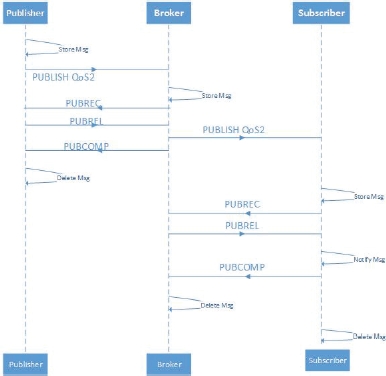
Figure 5.6. MQTT quality of service 2. For a color version of this figure, see www.iste.co.uk/ali-yahiya/tactile.zip
5.5.2. Constrained Application Protocol (CoAP)
The CoAP is an asynchronous web transfer protocol, optimized for constrained nodes in IoT and M2M network applications. It is designed for low-power and lossy wireless networks. The standard was proposed by IETF in 2014 (Internet Engineering Task Force 2014). Like HTTP, it uses the REST model and RESTFul API, which is used in web services. It is mainly used in low-power wireless IoT applications, with an IPv6 network layer on a simple 8-bit microcontroller. The “constrained” adjective is added because of the low-power wireless network used with the IPv6 network layer, such as 6LoWPAN, and also due to the devices that need constrained resources.
The structure of the message header is shown in Figure 5.7, where (Ver) is a 2-bit field for determining the version of CoAP, T is a 2-bit field for determining the type of message, for example CON (confirmable), NON (non-confirmable), ACK token length, and TKL, which is a 4-bit field for the indication token field. The code field specifies whether the message is a request. The message ID field is used for the detection of duplicate messages (acknowledgment) or RST (reset), of variable length of response or empty. Figure 2.14 shows the structure of the message header.

Figure 5.7. The structure of the CoAP protocol message header
The architecture of participating entities in CoAP is a client–server one. The server makes resources available under a URL, and the clients access these resources using methods such as GET, PUT, POST and DELETE.
A useful feature of CoAP is the possibility of sending confirmable and unconfirmable messages. When the receiver gets a confirmable message, it will return an acknowledgment. If the sender did not receive the acknowledgment, it will continue to send until a timeout is attained.
The CoAP runs over UDP and supports the use of multicast IP destination addresses. This is useful in IoT applications where a sensor wants to send a reading to multiple endpoints. In the multicast case, to prevent the congestion of the network, a non-confirmable message is sent. However, if a request needs a response by the server, it should not respond immediately, but after a period of leisure.
The architecture in Figure 5.8 shows how the constrained network is connected to the Internet with or without a proxy. The CoAP protocol can either be mapped to the HTTP through a proxy or establish a direct connection between a resource providing the server on the Internet and the request originating client. The nodes (c) are connected in the constrained network using CoAP, where they can function as sender and recipient endpoints.
Concerning security, as mentioned in the case of MQTT, the three elements authentication, encryption and integrity are guaranteed by using datagram transport layer security (DTLS) over UDP (see Datagram Transport Layer Security Version 1.2 by Internet Engineering Task Force (2012)).
Web-of-Things, in analogy to the IoT, uses web browsers to communicate with things by applying the RESTful paradigm (Richardson et al. 2007; Mingozzi et al. 2014) to constrained devices. The CoAP is designed for this case since it is a version of HTTP with a reduced overhead and limited complexity, which fits the limited capabilities of constrained devices. As shown in Figure 5.8, the clients can ask for services from the nodes, using the REST interface in the same way as when accessing web services. For example, resource discovery GET is used to discover all of the devices.

Figure 5.8. CoAP architecture. For a color version of this figure, see www.iste.co.uk/ali-yahiya/tactile.zip
5.5.3. Data Distribution Service for real-time systems (DDS)
The Object Management Group (OMG) DDS standard is the first open international standard directly addressing publish-subscribe middleware for real-time systems. Its most remarkable features are the real-timeliness, reliability and delivery deadlines. Hence, it is convenient for distributed systems. Other advantages of this protocol are its dynamic scalability and its support for one-to-one, one-to-many and many-to-one and many-to-many communications. The DDS application middleware can be compiled for any platform thanks to the platform-specific mapping of interface definition language (IDL), which is a descriptive language used to define data types and interfaces independently of the programming language or operating system/processor platform.
DDS is a data-centric protocol where publisher nodes transmit the state (data) of their world and update it if an attribute changes. The communication infrastructure will maintain the status. The subscribers interested in the data, also called “topic”, will subscribe to the topic to be updated. Fields of a given topic “key” will provide detailed specifications of the data. This is in contrast to a message-centric system, where commands are sent to change the world’s state, which will be reconstructed by an application on the remote client node. The difference between data-centric and message-centric is demonstrated in Figure 5.9, where the client node application memorizes the states in the message-centric system. The messages (commands cis) coming from another node will modify the state in the destination client addressed by the transport and network layers. In other words, the messages are verbs of action to the destination clients. In data-centric, the transport layer is aware of the destination as a client subscribes to a data name and type. The data is then analogous to “nouns” compared to the messages equivalent to “verbs” in languages.
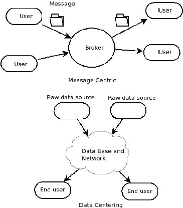
Figure 5.9. Data-centric versus message-centric
As shown in Figure 5.10, the DDS architecture consists of DomainParticipant, Publisher, Subscriber, DataWriter, Topic and DataReader entities. The DomainParticipant is the top-level entity in the architecture. It is created by an application and is used to join a DDS domain, where a DDS domain is a logical network of applications that can communicate with each other. In other words, a DomainParticipant is a container for entity objects that all belong to the same DDS domain. The DomainParticipant creates other entities such as the DataWriter and DataReader. The former writes typed data on a topic. An aggregation of DataWriter objects makes a publisher that disseminates information. The DataReader reads typed data from a topic, an assembly of them is responsible for receiving data. Concerning the bus system, DDS uses UDP by default, but it can also support TCP. An interoperability problem may result from different transport protocols used by the vendors in their implementation of the DDS. To overcome this problem, the real-time publish subscribe (RTPS) (Object Management Group 2018b) wire protocol is used. It represents the DDS interoperability protocol that allows data sharing among different vendor implementations.

Figure 5.10. Architecture of a DDS protocol to connect applications systems. For a color version of this figure, see www.iste.co.uk/ali-yahiya/tactile.zip
Compared with the MQTT, the DDS does not depend on a broker and different clients can communicate in a peer-to-peer manner.
DDS’s QoS policy is such that each entity has an associated QoS comprised of a list of policies, depending on the entity type (see Comprehensive Summary of QoS Policies (Cheat Sheet) by Real-Time Innovations, Inc. (2013)). It configures the different aspects of the entity’s behavior. For example, a DataWriter on a Publisher can offer a QoS contract where it commits to provide data each deadline period. A DataReader on a Subscriber requires a QoS contract that expects data reading each deadline period. A publisher can also “promise” whether it will use a best-effort UDP-like or reliable TCP-like protocol for transport. A subscriber can tell the middleware that it only wants to see every third topic sample and/or only the samples in which the specific data-field-filtering criteria are met.
Regarding the protocol’s security model, DDS has a service plugin interface (SPI) architecture (Object Management Group 2018a) at the middleware level. This allows users to customize authentication, control access, encrypt, authenticate messages, sign digitally, and log and tag data.
In Yuang Chen (2016), a quantitative comparison of latency, bandwidth and packet loss point of views is done. DDS shows good reliability and latency performance with respect to similar TCP publisher/subscriber protocols like MQTT. The price to pay for this is the increased bandwidth used by DDS. For more detailed references, the reader can refer to de C Silva et al. (2019), where a comparison with other IoT protocols is given.

Figure 5.11. Architecture of the OMA-DM protocol. For a color version of this figure, see www.iste.co.uk/ali-yahiya/tactile.zip
5.5.4. Open Mobile Alliance Device Management (OMA-DM)
This protocol allows management commands to be executed on nodes. It is based on where a DM server sends secure management commands to a client and a DM session consists of a request/response transaction (see OMA Device Management Protocol by OMA (2016)). The server manages the client nodes in two ways, either by reading and setting parameter keys and values or by installing, upgrading or uninstalling software elements when running software on the client side.
A session consists of two phases: setup and management. In the former, authentication and device information is exchanged. In the latter, the server will issue commands to be processed by the client. The communication messages and data use the XML format.
Figure 5.11 shows the architecture of the protocol. The server and client connection is either a wired (USB, RS-232 or Ethernet) or wireless physical layer (GSM, CDMA or Bluetooth). Regarding the transport layer, it is the same as in HTTP.
The security level of this protocol is not high. It is only based on authentication by sending credentials from the client, which will get authorization from the server. The credentials are hashed using MD5 crystallographic hashing.
5.6. Internet of Everything (IoE)
So far, we showed that the IoT is mainly a monitoring and automated data collection system, using sensors, embedded systems and Internet as the communication medium. In other words, the flow of information is mainly in one direction, from the object (devices or machines) towards a server where the information is processed and monitored, meaning that the IoT is a passive system in its functioning. However, simple commands can be sent from the monitoring side to take action on the device side, such as remotely switching a device ON and OFF, using human or machine interaction.
Now let us think about the effect of many other connected objects around the initial object that generates correlated data. Suppose that these objects’ functions are related by determining how each object works with the rest. A process adopts this relation to provide a greater value to the ensemble. An example of such multiple connected objects is an automated home with many connected devices, such as an air conditioner, an oven, a coffee machine, a TV, ventilation windows and a garage door. These objects will generate heterogeneous data, which may be incompatible, correlated and/or independent. A process is an algorithm that manages objects’ data, according to their relationship and the data they provide. After data manipulation, the process delivers the right information to the right machine or person at the right time. People or business managers can interact with this process through the Internet for its configuration. This whole system, composed of things, networks, people, data and processes, makes the Internet of Everything system.
The IoE system uses hyper-connectivity between smart objects generating data, people connected through a social media network and algorithms that deal with the considerable amount of data generated by the smart objects and people. Figure 5.12 shows the different constituents of an IoE system, as suggested by Cisco. Therefore, other technologies are necessary for IoE in contrast to the simple connectivity of the IoT. In the following section, we explain these enabling technologies.

Figure 5.12. People, process, things and data interactions. For a color version of this figure, see www.iste.co.uk/ali-yahiya/tactile.zip
5.6.1. Enabling technologies for the IoE
Technology is the basic driver for the emergence of IoE. The enabling technologies, mainly related to the smartness of the objects listed by Langley et al. (2021), are:
- – interconnectivity: the interconnection of many devices, with their smart ability in sensing and reacting to the environment, helps in increasing the smartness of the IoE, by exchanging quality data through a network of specialized smart components. Computational power for the interconnected devices can be added through either edge computing or cloud services;
- – big data: improved algorithms to interpret the increasing amount of quality data is another key enabler of IoE. Thanks to distributed systems, it is now possible to deal with significant volumes of data near the source, without sending it through the network. This local, close to the source, analysis will endow the devices with an adaptive optimized behavior, such as energy efficiency;
- – artificial intelligence (AI): the connected devices should be smart and autonomous in sensing reasoning, making decisions and performing actions. These capabilities are provided by AI systems and algorithms;
- – semantic interoperability: heterogeneous connected devices should understand and exchange information, data and knowledge in a meaningful way, in the same manner as the semantic web, which allows heterogeneous data in web pages to be structured, linked and retrieved. The development of successful interoperability between devices can be how things and systems expose data and metadata through API. In this case, the devices should share information concerning these APIs.
The range of IoE applications will depend on the smartness of the things (Langley et al. 2021). The higher level of smartness of things will increase their collaborative capabilities, which will impact the business models by opening up new opportunities. Also, increased smartness moves the system connectivity from closed to open interoperable systems.
5.7. Protocol comparisons and the readiness for TI
Previously, we listed the communication protocols used in IoT systems. Here, we compare them and investigate the possibility of them being used in a TI system. Table 5.2 summarizes their comparison using different aspects: applications, QoS, data dissemination and interoperability.
The comparison shows that DDS conforms to the TI requirements the most across many aspects. The most important one is real-timeliness, which is critical in the case of TI systems. No work has been found applying the DDS protocol for data exchange between master and slave devices. It is mainly because in TI applications, only a single master is used. The DDS could be a solution for a collaborative TI application where many masters can intervene. For more insight, Yang et al. (2012) used it in industrial applications, with a detailed analysis of the latency between nodes.
Table 5.2. Comparison IoT protocols
| DDS | MQTT | CoAP | OMA-DM | |
|---|---|---|---|---|
| Architecture | P2P | Broker based | Client/server | Client/server |
| Transport | UDP/TCP/RTPS | TCP | UDP | localUSB and HTTP |
| Data dissemination | Unicast, multicast | Unicast, multicast | Unicast | Unicast |
| QoS | 20 criteria | four levels | Message acknowledgment based | Not available |
| Interoperability | Different platforms and programming languages | Different platforms and programming languages | different platforms and programming languages | Different platforms and programming languages |
| Real-timeliness | yes | no | no | no |
5.8. TI-IoT models and challenges
Following the brief review of the IoT architecture and protocols, a comparison between the IoT and TI technology is necessary. A reference architecture for TI is suggested in the IEEE P1918.1 standards, as shown in Figure 5.13. Comparing it to the one for IoT, given in Figure 5.1, reveals many similarities. However, a more in-depth analysis will show the main differences as follows:
- – the devices: in IoT, the devices used can be, in addition to sensors/actuators, data-carrying devices connected to the physical device to send and receive data for automation and monitoring purposes;
- – the connectivity: the connectivity of devices to the network can be wired or wireless. Since the TI’s essential requirement is the ultra-low latency and availability, this restricts the connectivity possibility to 5G networks. While most IoT services are not real-time, connectivity through Ethernet connection, WiFi, NB-IoT and LTE-M is possible;
- – data processing and communication protocol: in the TI, the data is streaming continuously in real time, while in IoT, the information is mostly in a burst that can be aggregated, processed and stored, before monitoring or utilization for automation purposes;
- – cloud: in the IoT, the cloud is used for IaaS (Infrastructure as a Service) or PaaS (Platform as a Service), but also for data processing. The cloud is not available in the TI since the data should be conveyed by the network in real time. The communication network is then called the network domain;
- – the applications and services exist in both the IoT and TI to provide the required services, using the application layer to collect and preprocess data from sensors in order to decode and direct received data to actuators.

Figure 5.13. IEEE P1918 Tactile Internet reference architecture (Holland et al. 2019). For a color version of this figure, see www.iste.co.uk/ali-yahiya/tactile.zip
A summary of the comparison is given in the Table 5.3, from different requirement aspects.
Table 5.3. Summary of IoT-TI comparison
| Requirement | IoT | Tactile Internet |
|---|---|---|
| Real-time | Non-real-time | Real-time with reaction time (1–10 ms) |
| Function | Monitoring, data processing and control | Control with feedback † |
| Connectivity | Internet, wired and wireless | 5G |
| Data processing | Aggregation, analytic | Haptic data compression and modeling |
| Architecture | Three- to five- layers (devices, edge, network, cloud, application) | Master domain, network domain, teleoperated domain |
| Applications | (Non-critical) agriculture, smart city | (Critical) health care, traffic, robotics and manufacturing |
| Scalability | Large-scale deployment | Near-future large-scale deployment |
| Network and interfaces | Simple availability and reliability | High availability and reliability |
| Control process | Automated | Interactive |
| E2E communication model | Client–server | Master–slave |
| Power consumption | Restricted power consumption | No restrictions |
| Network configuration | Centralized around the server | End-to-end connection |
| Human interaction | Human in the loop to monitor and manage remotely | Human in the loop to control remotely (human-to-robot) |
The challenges facing the IoT technology development can be classified as technological, environmental and societal. More specifically, they concern security, scalability, connectivity and access control of IoT systems. The increased number of connected devices will have negative environmental consequences from energy consumption and generated e-waste. This may be controversial because the IoT technology optimizes and reduces power consumption when used for home automation, smart city and energy grid control, and also, when used in agricultural applications to optimize water consumption. Hence, IoT is an opportunity and a challenge (Radu 2018). On the societal level, the increased services provided by the IoT technology, such as surveillance cameras, are beneficial in reducing the number of crimes. However, they can cause some concerns among civil rights advocates.
The main challenges facing TI implementation are the ultra-low latency of round trip of a data packet, high reliability, availability of connection and safety and security of the TI application. The available communication technology to support the above challenges is 5G.
To sum it up, IoT and TI, with the advent of 5G, share many similarities and some subtle differences. The difference is clarified in the mode of human interaction in the case of TI, which is human-centric, and the machine is complementing and augmenting human capabilities (Maier et al. 2016).
5.9. Edge computing in the IoT
The deluge of data generated from the proliferation of connected objects to the Internet on one hand, and the convergence of IoT and cloud techniques on the other, will require cloud processing power and storage. This may increase the load on the network to unacceptable ranges. An efficient solution to this problem is to process at the cloud’s edge, close to the data source. Edge or fog computing is added to the IoT architecture to decrease this load, by offering some processing, like data analysis, closer to the source. In a use case, such as a smart city, global handling of the massive amount of data generated by the different city services is needed, rather than a siloed processing of other city areas: public lighting management, health care system, car parking and public transportation. The transmission of the increased amount of data over the network will result in congestion with a degraded QoS, due to the increased transmission delays and the decreased throughput. For example, a delayed health care emergency has a severe impact.
Historically, edge computing can be traced as follows (Khan et al. 2019): the computer systems evolved from the mainframe, where all of the processing power is confined in, to independent smaller desktops. However, the desktop is attained in computing power and memory space. The earlier solution was to connect them to a server system located closer to them in a client–server manner, in order to serve many desktops simultaneously. The growth of the number of software applications to increase productivity added more expenses to users, therefore, the cost of license rights, on one hand, and the cost of infrastructure and platforms, on the other hand, needed to be reduced. The computing power has again been shifted towards the network to establish a cloud system of distributed computing and memory platforms across the Web. Later, with the advent of mobile computing devices and their capability to connect to the network ubiquitously, the need appeared for fixed computing devices within the core network to support them in a cloud system. Finally, the proliferation of the IoT devices and the increased demand for computing power required the extension of the cloud computing resources towards the end devices (edge computing), in order to decrease the cloud network congestion with unuseful flow to reduce the latency. Figure 5.14 shows how the computing power shifts to the edge through three different configurations, which will be explained in the next sections.
The main aim of concentrating the computational power is to reduce the expensive computing hardware and memory facilities; this attributes features such as, resource pooling and storage capacity to the small IoT devices connected to the network.

Figure 5.14. Edge computing in IoT systems. For a color version of this figure, see www.iste.co.uk/ali-yahiya/tactile.zip
5.9.1. Edge computing paradigms
Many projects in academia and industry supported edge computing, such as cloudlet, fog, mobile edge computing (MEC), Nebula and FemtoCloud, among others (Pan and McElhannon 2018), to implement the edge computing paradigm. Moreover, software-defined networks (SDN) and virtualized network functions (VNF) combined with the cloud edge platforms will virtualize the network, automatically configure IoT devices connected to the network and add new virtual functionalities, as shown in Figure 5.15. The virtualization of the network is useful in providing reliable connectivity. In contrast, the functionalities’ virtualization is useful for changing or adding new services and functionalities to the network. Both VNF and SDN solve the problems of heterogeneity, interoperability and scalability of IoT devices.

Figure 5.15. SDN and VNF in the core network and the MEC access to them. For a color version of this figure, see www.iste.co.uk/ali-yahiya/tactile.zip
Cloudlet is based on a multi-tier architecture, where the Cloudlet is a computing device or a “data center inside a box” located between the Internet and the mobile units. It is close to the end-users’ wireless mobile or wired device, generally any “thin client” device. Inside the box, virtual machines (VMs) are instantiated and allocated dynamically according to the end devices requests for assistance. Similar to Cloudlet, (Bonomi et al. 2012) it aims to provide compute, storage and services in the proximity of the end-users, as well as to reduce network congestion, E2E latency and enhanced security levels by reducing the core environment operations. However, sophisticated security algorithms should be embedded on the edge devices. The difference between these two technologies is that the first is an academic project and the latter is from the industry. The mobile-edge computing (MEC) initiative from ETSI (2016) is to prepare the transition towards 5G and the IoT. It aims to provide a new ecosystem and value chain for different actors: application developers, content providers, network operators and customers. The MEC servers are deployed at the base stations, such as LTE (eNodeB) and 3G Radio Network Controllers (RNC). The main difference between Cloudlet, Fog and MEC is that MEC is mainly focused on cellular networks.
To summarize, the SDN and NVF enable technologies for edge computing to easily access the edge computing devices for their configuration and management. While these technologies are developing, Cloudlet, Fog and MEC architectures are suggested to implement the early edge computing systems in cloud-based networks. The MEC and Fog architecture can be more adapted to IoT applications.
A detailed survey on mobile edge computing is given in Mao et al. (2017). A use case example of heavy edge computing is provided in Li et al. (2018), where deep learning is introduced at the edge to analyze the offloaded data from the end devices (nodes).
5.10. Real-time IoT and analytics versus real time in TI
The pervasive characteristic of the IoT leads to huge data from several smart connected objects. On the other hand, humans are part of the IoT system interaction, since it collects users’ information. Therefore, a real-time analysis of the amount of automated data generated from heterogeneous and distributed sources is essential to extract useful information for humans. Nevertheless, the real-time analytics required for IoT systems is not as critical as in TI. The TI criticality is inherent since real-time communication is required for a kinesthetic return signal from a teleoperated system to the human operator (Haddadin et al. 2019). However, in IoT applications, real time stands for a fast response, without a deadline constraint to respect.
5.11. From IoT towards TI
Following the connection of millions of computers using the Internet and millions of mobile phones via the wireless network to the Internet, billions of objects are now connected via the Internet and wireless networks, merging the physical world and the virtual world. Up until the advent of IoT, the Internet provided a connection from anywhere, at any time, for anything and anyone, for any service and on any network (Vermesan et al. 2009). Currently, with the advent of 5G, any haptic interaction experience is realized, where it provides the infrastructure and medium to establish haptic communications. The essential requirement for any haptic interaction dimension is low latency transmission. This additional dimension is a leap in today’s IoT technology for the Tactile Internet, which delivers physical, tactile experience remotely. Figure 5.16 shows that IoT and TI may share the mission-critical communication that can be provided by 5G, which can be useful for both.

Figure 5.16. Mission-critical communication for IoT and TI (Zhang and Fitzek 2015). For a color version of this figure, see www.iste.co.uk/ali-yahiya/tactile.zip
As in the case of the IoT, some enabling technologies are RFID, wireless networks and sensors, and embedded system miniaturization. In the case of the TI, ultra-low latency reliable connection is the enabling technology. The range of applications between IoT and TI is different, as shown in Table 5.3, but both are built around sensors and actuator devices and network connection. Figure 5.17 shows the similarities and differences between the IoT and TI, where the main difference to be noted is the ULLRC constraint on the haptic communications through the network and the human in the loop, since the interaction with the remote physical world is through tactile perception.
The most appealing application, among others, of TI would be the teleoperation of robots. In such applications, a complex system, such as a robotic arm, is remotely controlled, with haptic feedback to the master controller to improve the remote arm control, while it evolves in the environment. The haptic sensors supply details of the object that the user is interacting with in real time. The next chapter tackles this remote robotic control via a network system to provide the required Quality of Experience (QoE) and the quality of the executed task on the slave side. Haptics will play a significant role in the future Internet, which can be the critical point of entry into a full-sensory virtual reality. It will create augmented reality and the sensation of immersion. The capacity to uniquely address most objects of our real world, with the help of haptics, makes it possible to create an augmented world that will increasingly resemble our physical world and reduce the gap between the digital and physical worlds.

Figure 5.17. Communality and difference between the IoT (bottom) and the TI (top). For a color version of this figure, see www.iste.co.uk/ali-yahiya/tactile.zip
5.12. Conclusion
This chapter covered the IoT architecture and the communication protocols of IoT. It presented the connection of objects to the Internet and M2M. The aim was to follow the evolution of the connected things’ paradigm to the tactile experience paradigm, focusing on the communication protocols, specifications and applications. We were reminded of the three- to five-layer architecture of IoT. An edge device is an interface that can extend between the end device and the cloud. A local network can also exist between the end device and the edge closer to the device. This layer provides connection and communication operations, in addition to some computational functions. The cloud centralizes the whole system. Service applications are offered, such as data analytics, monitoring and centralized device management. It is reminded that connectivity, edge capabilities and security are the main challenges faced in IoT systems and their communication protocols.
The Internet of Everything expands the IoT concept by including data, people, processes, and network connectivity.
Regarding the TI, a standard three-layer architecture consisting of the master domain, network domain and slave domain is the dominant one. Most of the computations are held in the slave and master domains, while the network domain provides a reliable low latency connection between the master and slave domains. The latter two properties of the network domain are also the main challenges for a TI operation, especially for critical systems. TI is not next generation IoT. However, a new paradigm, such as the Tactile IoT can emerge in the future, when the physical world is merged with the virtual and digital worlds and then is again transformed into the physical world at the other end of the connection.
5.13. References
Acatech. (2011). Cyber-Physical Systems. Springer-Verlag, Berlin.
Bonomi, F., Milito, R., Zhu, J., Addepalli, S. (2012). Fog computing and its role in the internet of things. Proceedings of the First Edition of the MCC Workshop on Mobile Cloud Computing, MCC 12. Association for Computing Machinery, New York, 13–16 [Online]. Available at: https://doi.org/10.1145/2342509.2342513.
de C. Silva, J., Rodrigues, J.J.P.C., Al-Muhtadi, J., Rabêlo, R.A.L., Furtado, V. (2019). Management platforms and protocols for internet of things: A survey. Sensors, 19(3), 676.
ETSI (2016). Mobile Edge Computing (MEC); Framework and Reference Architecture. ETSI GS MEC 003 V1.1.1.
Gardašević, G., Veletić, M., Maletić, N., Vasiljević, D., Radusinović, I., Tomović, S., Radonjić, M. (2017). The IoT architectural framework, design issues and application domains. Wireless Personal Communications, 92, 127–148.
GrØnbæk, I. (2008). Architecture for the Internet of Things (IoT): API and Interconnect. Second International Conference on Sensor Technologies and Applications (SENSORCOMM 2008), 802–807.
Haddadin, S., Johannsmeier, L., Díaz Ledezma, F. (2019). Tactile robots as a central embodiment of the tactile internet. Proceedings of the IEEE, 107(2), 471–487.
Holland, O., Steinbach, E., Prasad, R.V., Liu, Q., Dawy, Z., Aijaz, A., Pappas, N., Chandra, K., Rao, V.S., Oteafy, S., Eid, M., Luden, M., Bhardwaj, A., Liu, X., Sachs, J., Araúo, J. (2019). The IEEE 1918.1 “Tactile Internet” standards working group and its standards. Proceedings of the IEEE, 107(2), 256–279.
Internet Engineering Task Force (2014). The Constrained Application Protocol (CoAP) [Online]. Available at: https://tools.ietf.org/html/rfc7252.
Internet Engineering Task Force (2012). Datagram Transport Layer Security Version 1.2 [Online]. Available at: https://tools.ietf.org/html/rfc6347.
Jamali, M.A.J., Bahrami, B., Heidari, A., Allahverdizadeh, P., Norouzi, F. (eds) (2020). IoT architecture. Towards the Internet of Things Architecture, Security and Applications. Springer.
Kayal, P. and Perros, H. (2017). A comparison of IoT application layer protocols through a smart parking implementation. 20th Conference on Innovations in Clouds, Internet and Networks (ICIN), 331–336.
Khan, L.U., Yaqoob, I., Tran, N.H., Kazmi, S.M.A., Dang, T.N., Hong, C.S. (2019). Edge computing enabled smart cities: A comprehensive survey [Online]. Available at: http://arxiv.org/abs/1909.08747v1.
Langley, D.J., van Doorn, J., Ng, I.C., Stieglitz, S., Lazovik, A., Boonstra, A. (2021). The internet of everything: Smart things and their impact on business models. Journal of Business Research, 122, 853–863 [Online]. Available at: https://www.sciencedirect.com/science/article/pii/S014829631930801X.
Laszlo, M. (2014). Cyber-physical production systems: Roots, expectations and R&D challenges. Procedia CIRP, 17, 9–13.
Li, H., Ota, K., Dong, M. (2018). Learning IoT in edge: Deep learning for the Internet of Things with edge computing. IEEE Network, 32(1), 96–101.
Maier, M., Chowdhury, M., Rimal, B.P., Van, D.P. (2016). The Tactile Internet: Vision, recent progress, and open challenges. IEEE Communications Magazine, 54(5), 138–145.
Mao, Y., You, C., Zhang, J., Huang, K., Letaief, K.B. (2017). A survey on mobile edge computing: The communication perspective. IEEE Communications Surveys Tutorials, 19(4), 2322–2358.
Mingozzi, E., Tanganelli, G., Vallati, C. (2014). Coap proxy virtualization for the web of things. IEEE 6th International Conference on Cloud Computing Technology and Science, 577–582.
Pan, J. and McElhannon, J. (2018). Future edge cloud and edge computing for internet of things applications. IEEE Internet of Things Journal, 5(1), 439–449.
OASIS (2019). MQTT Version 5.0 [Online]. Available at: https://docs.oasis-open.org/mqtt/mqtt/v5.0/mqtt-v5.0.pdf [Accessed January 2021].
Object Management Group (2018a). DDS Security [Online]. Available at: https://www.omg.org/spec/DDS-SECURITY/About-DDS-SECURITY/ [Accessed January 2021].
Object Management Group (2018b). The Real-time Publish-SubscribeProtocol (RTPS) DDS Interoperability Wire Protocol Specification [Online]. Available at: https://www.omg.org/spec/DDSI-RTPS/2.3/Beta1/PDF.
OMA (2016). OMA Device Management Protocol [Online]. Available at: http://www.openmobilealliance.org/release/DM/V1_3-20160524-A/OMA-TS-DM_Protocol-V1_3-20160524-A.pdf.
Radu, L.-D. (2018). Environmental issues in internet of things: Challenges and solutions. Acta Universitatis Danubius, Œconomica, 14(1), 20–32 [Online]. Available at: http://journals.univ-danubius.ro/index.php/oeconomica/article/view/4250/4393.
Real-Time Innovations, Inc. (2013). Comprehensive Summary of QoS Policies (Cheat Sheet) [Online]. Available at: http://community.rti.com/rti-doc/500/ndds.5.0.0/doc/pdf/RTI_CoreLibrariesAndUtilities_QoS_Reference_Guide.pdf.
Richardson, L., Ruby, S., Hansson, D.H. (2007). Restful Web Services. 1st edition, O’Reilly Media [Online]. Available at: http://gen.lib.rus.ec/book/index.php?md5=569428a49f833a9ee3f50d0c010ab4c.0.
Taivalsaari, A. and Mikkonen, T. (2018). A taxonomy of iot client architectures. IEEE Software, 35(3), 83–88.
Vermesan, O., Friess, P., Guillemin, P., Gusmeroli, S., Sundmaeker, H., Bassi, A., Jubert, I.S., Mazura, M., Harrison, M., Eisenhauer, M., Doody, P. (2009). Internet of things strategic research roadmap. In Internet of Things – Global Technological and Societal Trends, Vermesan, O. and Friess, P. (eds). River Publishers, Aalborg.
Yang, J., Sandström, K., Nolte, T., Behnam, M. (2012). Data distribution service for industrial automation. Proceedings of 2012 IEEE 17th International Conference on Emerging Technologies Factory Automation (ETFA 2012), 1–8.
Yuang, C. and Thomas, K. (2016). Performance evaluation of IoT protocols under a constrained wireless access network. International Conference on Selected Topics in Mobile Wireless Networking (MoWNeT), 1–7.
Zhang, Q. and Fitzek, F.H. (2015). Mission critical IoT communication in 5G. In Future Access Enablers of Ubiquitous and Intelligent Infrastructures, Atanasovski, V. and Leon-Garcia, A. (eds). Springer, Cham.