
7
Haptic Data: Compression and Transmission Protocols
Wrya MONNET
Department of Computer Science and Engineering, University of Kurdistan Hewlêr, Erbil, Iraq
7.1. Introduction
The architecture and the mathematical model of a remote-controlled robot were presented in Chapter 6. The primary returned signal used to control the remote robot was the force signal. This signal is, in fact, a haptic, and more specifically, a kinesthetic signal, which contains information about the remote environment for a better control command by the human operator. Tactile signals can also be returned to the human operator to improve the perception of the manipulated objects. The haptic signals then enhance the compliance of the remote robot with the environment and things.
The transmission of the haptic signals from the slave side to the master through the communication channel should have an acceptable quality. In this chapter, haptic signal characteristics are presented along with their perception by machines and humans. Understanding the perception by humans helps to find a way to reduce redundancy and compress them for an efficient transmission bandwidth use.
Haptic interface devices, which are force-reflecting interfaces, are the control tool used in telerobotics for a dexterous hand manipulation of the remote environment and objects. The working principles of some commercial haptic interface devices and some haptic sensors and actuators are presented.
Finally, some communication protocols are given for the transmission of such signals over the Internet. These should have near-real-time performance since the human perception of haptic signals is within 1 ms; hence, very low transmission delay is required to transmit such signals.
7.2. Haptic perception
Unlike other senses, there is no independent organ for humans to provide the sense of touch. The sense of touch is distributed all over the skin with haptic receptors to collect the information. Since most robots are a close imitation of humans, this sense should also be distributed on robots’ contact areas with objects and environments. A brief presentation of the human haptic sensors is given in the following sections, based on which the robotic sensors are built. This is followed by an explanation of how the robots perceive and model the manipulated objects.
7.2.1. Human haptic perception
Human haptic receptors reside and are distributed in the skin to form the sense of touch. These receptors can detect pressure, heat, cold and pain (Schmidt 1986). Pressure sensors or mechanoreceptors are the ones responsible for haptic and tactile sensations. These receptors have an absolute and relative threshold value of detection. Concerning the absolute perception, this results from the deformation of the skin due to applied pressure. As such, indentations of the skin of the order of magnitude of 0.01 mm (10 μm) suffice to produce tactile sensations when they occur on the inner surface
where ΔI is the difference threshold (JND), I is the initial stimulus and k is the constant that signifies that the ratio stays constant. The above Weber equation states that the psychophysical perception of a signal change is therefore proportional to the stimulus intensity itself. In general, the JND for human haptic perception ranges from k ≤ 15%. If a change in haptic force magnitude is less than this range, the user would not perceive that force (Nitsch et al. 2010). The margin of no perception can be used for data compression, as we will see in section 7.4.
7.2.2. Telerobotic tactile and haptic perception
The main control operation of a teleoperated robot in the Tactile Internet comes from the operator at the master domain. The role of sensing is to detect information before encoding it and conveying it by a communication channel for reproduction on the teleoperator side. The information consists of the status of the environment surrounding the slave robot. The teleoperation is then composed of a fast continuous, uninterrupted sensing, encoding and reproduction of tactile sensations. However, intermittent autonomous behavior may also be required on the slave side to encounter any extended delays in the sensory signals’ continuous feedback loop to the master operator. This is similar to a human who acquires sensory-motor coordination through learning based on a considerable amount of sensed data accumulated in past practices, as shown by Arimoto et al. (2005); Inoue and Hirai (2014), who show the analogy of this human capacity on the two-finger robotic hand. In these works, a model and a proportional–integrative–derivative (PID) control system are used to grasp objects without the need for tactile sensing on the robotic fingertips. However, most grasping robotic hand systems depend on tactile sensing for the controller feedback. In such cases, perception of the object’s material and shape is essential for a local assistance of the master-slave controlled robots.
A perception process is required to interpret and represent touch sensing information to observe and determine the object properties and a model for eventual local decision-making. It is essential in the absence or interruption of master control signals to let the telerobotic recognize unintentional collisions or make intentional physical contact with objects or humans, or in other words to improve environmental awareness when dealing with objects and humans.
The detection and perception of the materials and objects by a telerobot is not only useful for autonomously executed tasks and local decisions, but it can also be used in the compression of feedback signals used for the master domain reconstruction since realistic sensing is required for the distant human operator with minimum bandwidth utilization. As a result of the perception, some packed parameters extracted from a model can be fed back to the master to reconstruct the haptic effects on the master side. In addition to models, machine learning can also be used by the robot tactile sensing to recognize objects according to their properties and materials, which can be done to a very good extent (Xie et al. 2019).
For authentic feedback, the relevant tactile information for TI or telepresence applications extracted from sensing data are the shape, material properties and the object pose (Luo et al. 2017). In the following sections, the different techniques for these types of sensing are covered.
7.2.3. Tactile sensing for material recognition
The functioning of the Tactile Internet is comparable to a prosthetic hand device with tactile sensing feedback used to improve the grasp task’s success rate. Therefore, an object’s surface material properties are essential for an interactive action with the surrounding environment. The most critical parameters to be detected and conveyed by a slave robot to the human master are the surface texture and object stiffness. Tactile sensors detect the object’s surface by a sliding exploratory movement on their surfaces, while the object stiffness can be detected using force sensors. Concerning the texture, many types of sensors with their own data processing methods are available, such as acoustic sensors with a frequency domain analysis of the sensed data to detect the different textures. The stiffness, which is the inverse of compliance, shows the rigidity of the object. Compliance can be described as the relationship between an object’s deformation and the force applied to it. Therefore, one method to estimate the compliance is by measuring a given skin-like sensor’s deformation when using a constant force on it. Piezoresistive sensors with a linear variation of conductance as a function of the applied force, as shown in Figure 7.1, can be used in this case.

Figure 7.1. Piezoelectric resistance characteristic with applied pressure. For a color version of this figure, see www.iste.co.uk/ali-yahiya/tactile.zip
7.2.4. Tactile sensing for object shape recognition
The telepresence system assistance for the master side can be through identifying the shape of tackled objects. This can be for the aims of reconstruction, local control of objects or feature extraction for data compression. An object’s perception can be done using image processing and recognition techniques invariant with image scale, translation and rotation (Lowe 1999). However, this may not be very practical in the control tasks of telerobotic and telepresence applications. In the latter cases, tactile object perception is necessary. Two tactile senses will interact to perceive the objects: the cutaneous sense to recognize the local shape and the combination of cutaneous and kinesthetic senses to detect the object’s global contours. This can be summarized in the perception of a Rubik’s cube and a simple smooth cube shown in Figure 7.2.

Figure 7.2. Two cubes: (a) is different in its local shapes from (b) which is smooth. Both are globally a cube. For a color version of this figure, see www.iste.co.uk/ali-yahiya/tactile.zip
The sensors for this type of perception are mostly a two-dimensional array of sensors to detect the different amounts of applied force on the object. Figure 7.3 shows a tactile sensor organized in a matrix array of pressure sensors. Many data processing methods exist to recognize the local shape, such as raw data manipulation or statistical feature extraction. Otherwise, the data collected from the array of sensors can be seen as a two-dimensional image, with each sensor representing a taxel.
The local object recognition is then done by features adapted from computer vision applied to the array taxels such as moment estimation, feature extraction from the tactile image histogram, principal component analysis (PCA) and the data extract features. Finally, neural networks can be applied with unsupervised learning and incremental learning to classify objects. The latter method is also useful for global shape perception.
To estimate the global shape, the point cloud method is also used.
7.2.5. Tactile sensing for pose estimation
The object pose is not essential for Tactile Internet applications since vision assistance is also available for the master side. This helps with the localization and manipulation of objects with telerobotic arms and hands.
In summary, Table 7.1 shows the computational techniques used in object recognition using different tactile sensors and application domains. The table is extracted from a detailed review of the tactile sensing techniques of robot hands given in Kappassov et al. (2015).

Figure 7.3. Thin tactile sensor technology from (https://www.tekscan.com/). For a color version of this figure, see www.iste.co.uk/ali-yahiya/tactile.zip
Table 7.1. Overview of computational techniques applied to tactile sensing signals in the reviewed robot hand applications (Kokkonis et al. 2018)
| Tactile data type | Computational technique | Applications |
|---|---|---|
|
|
|
7.3. Haptic interfaces
A haptic interface consists of a mechanism, sensors, actuators and hardware to estimate the human movement and return the forces from the slave. The hardware controls the mechanism through its impedance. The mechanical impedance gives a close perception of the remote object or environment. The sensors provide the position data, which can be derived once or twice to provide velocity and acceleration information.
7.3.1. Haptic interface for telepresence
Haptic perception refers to both the cutaneous (tactile) and kinesthetic sense, which conveys important information about distal objects and events (Loomis and Lederman 1986). Haptic perception plays a significant role in telerobotics to enable an effective human–machine interface in addition to video and audio interfaces. These interfaces are also used to manipulate virtual objects, in CAD/CAM applications, before manufacturing them. Artificial sensors and actuators are used to capture and convey this information to remote sites. For example, in the bilateral telepresence system, both the master and slave domains are equipped with these sensors and actuators. On the master domain side, as explained before, the ensemble of the sensors and actuators is called the haptic interface. It is used to translate the operator’s manual dexterity while giving a realistic force reflection, position and touch feeling from the manipulator (slave domain).
Haptic interfaces enable human–machine communication through kinesthetic and tactile senses. Many anatomical parts of the human body, such as hands, skin and limbs, can provide the haptic communication channel between human and machine. However, the primary currently available commercial haptic interfaces are based on manual touch. A haptic exoskeleton is another way to communicate with a device. Commercial exoskeleton products for health and work, also called wearable robots, are available (https://exoskeletonreport.com/). These products are mainly known for personal and local uses other than for remote-controlled parts. However, in space research, more specifically the European Space Agency (ESA), a demonstration example of telepresence with exoskeleton can be found in Schiele (2014) and ESA (2014).
The haptic interface hardware design is based on a human contact scenario using hands, limbs or skin. It will also depend on the target application because of the complexity required to interface the human haptic sensory and mechanical movement. For example, suppose we need a plier gripper effector to execute a task at the slave domain in a telerobotic application. In that case, it is not necessary to use an exoskeleton-type haptic interface on the master side. A haptic interface’s hardware can vary from a gaming joystick, a multiple DOF stylus to a wearable exoskeleton device (Malley and Gupta 2008), for the kinesthetic to an array of factors for tactile sensing. Following the studies of Millman and Colgate (1991), Adelstein and Rosen (1992) and Minsky (1995) in force-reflecting and tactile interfaces, respectively, commercial haptic devices are now increasingly available. Figures 7.4 and 7.5 show some of the commercial haptic interface products available. Both haptic and tactile interfaces can be integrated into a single interface to feedback force and tactile from the remote device.
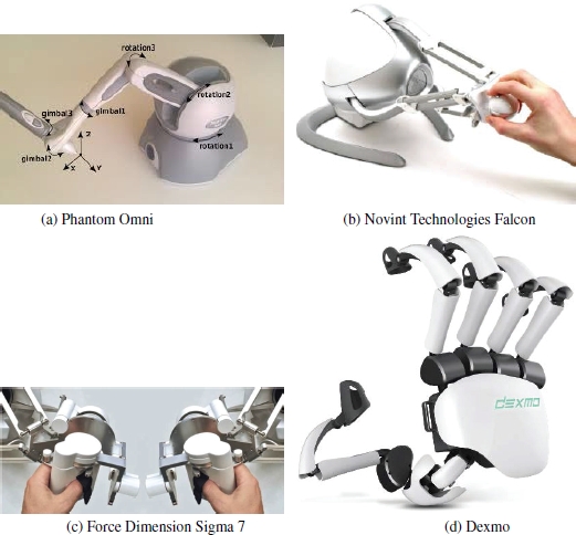
Figure 7.4. Some commercially available haptic interface devices. For a color version of this figure, see www.iste.co.uk/ali-yahiya/tactile.zip
In 1980, Bejczy (1980) listed the difficulties in the mechanical design of haptic interfaces due to several problems, “These problems concern linkage of joint geometry, kinematic redundancy and dexterity, structural stiffness and dynamics, actuators for power and precision, motion transmission within the manipulator, mathematics for geometry and dynamics of mechanical arms, properties of end effectors and mechanical evaluation criteria.”. He then listed the challenges in the human–machine interface research domain. Here are some that are still valid:
- – the form of the sensors should be adapted to the real-world environment (task);
- – the control and command language should be tailored to the mechanical, sensing and electronic properties of the manipulator system;
- – the interface with the operator should be such that to intensify his or her capabilities by using increased degree of freedom (DOF), 3- to 6-DOF devices are available commercially.
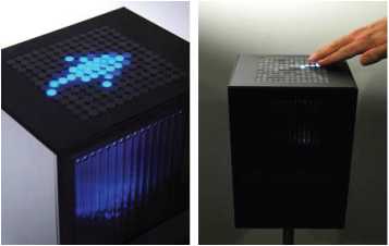
Figure 7.5. A tactile interface device: Lumen (Parkes et al. 2008). For a color version of this figure, see www.iste.co.uk/ali-yahiya/tactile.zip
To conclude this section, we cannot neglect the importance of video and audio information in telepresence applications. In fact, in industrial robotics, where automation plays the leading role, visual technologies are used by robots to outline objects. However, this is not sufficient; a more detailed and precise definition of objects and their handling are obtained using force-reflective sensing. In his visionary article, Sutherland (1965) argued that there is no reason only hands and arms should be used to control the computer due to their high dexterity. He adds that eye dexterity is also high and that machines to interpret eye motion will also be built. The range of interface devices, including haptic ones, can still increase based on new sensor and actuator technologies. In the following section, a list of haptic sensors and actuators is given as an example.
7.3.2. Haptic and tactile sensors and actuators
Tactile sensors are defined according to Lee and Nicholls (1999) as: “a device or system that can measure a given property of an object or contact event through physical contact between the sensor and the object”. The property of the object includes its shape and texture. Many authors provide reviews on the types of sensors and their working principles (Rossi 1991; Amato et al. 2013; Dahiya and Valle 2013). This section presents the different kinds of tactile and kinesthetic sensing devices and a brief about the basics of their functioning.
- – Resistive and piezoresistive sensors: the resistance of the sensor changes according to two variables; first, the contact position, and second, the contact force. The first variable is of the potentiometer type, and the second is of the piezoresistance type. In the potentiometer type, two resistive sheets are stacked in two layers. Each sheet is made of many lines of resistive voltage dividers, one horizontally and the other vertically. When stacked on each other, the two layers form a grid of resister circuits. When a point is pressed on the sheet, contact is made between the horizontal and vertical voltage dividers. The voltage dividers’ output voltage in x and y directions is a function of the position of the contact. In the same way as the resistive sensor, to add a contact force sensing capability, two-layer lines of conductors are stacked with a piezoresistance material between two layers (Robertson and Walkden 1985). A pressure exerted on the surface will create a variable resistance that can be scanned with a particular electronic circuit to locate the position and evaluate the force as shown in Figure 7.6. Another technique that allows measurement of multiple hybrid resistive tactile sensing is given by Hong Zhang and So (2002). Another type of sensor based on piezoresistive touch sensors is also given in Goger et al. (2009).

Figure 7.6. Working principle of a piezoresistive touch sensor (Robertson and Walkden 1985): (a) construction; (b) components and interfacing. For a color version of this figure, see www.iste.co.uk/ali-yahiya/tactile.zip
- – Capacitive sensors: capacitive measurement methods are widely used nowadays in human-computer interfaces such as touch screens and trackpads. The functioning principles are based on the capacitance variation, which is a function of the distance between the plates and the area of its plates as shown in Figure 7.7. When a force is applied to the capacitor where the normal force component changes the plates’ distance, the tangential force component changes the plates’ effective area. This change in capacitance is then converted into a voltage change.
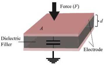
Figure 7.7. Parallel plate capacitor consisting of two parallel plates of area A separated by distance d (Dahiya and Valle 2013). For a color version of this figure, see www.iste.co.uk/ali-yahiya/tactile.zip
- – Optical sensors: one example of this type of sensor is based on the refraction in an optical waveguide plate (Ohka 2007) as shown in Figure 7.8. When a light beam is directed into the plate, it remains within it unless the surrounding refractive index is higher than the optical waveguide. This happens when the rubber sheet, featuring an array of conical feelers, is pressed. The canonical feelers are deformed on the plate surface, which reflects the light totally. The distribution of contact pressure is calculated from the bright areas viewed from the plate’s reverse surface. Another technique based on fiber Bragg grating (FBG) is given in Heo et al. (2006). Its working principle is based on the shifts in the reflected Bragg signal’s wavelength as a function of external parameters such as strain or force.
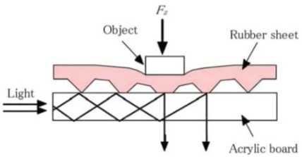
Figure 7.8. Principle of optical tactile sensor (Ohka 2007). For a color version of this figure, see www.iste.co.uk/ali-yahiya/tactile.zip
- – Ultrasonic sensors: this involves a medium for ultrasonic signals composed of thin rubber. An ultrasonic transmitter and receiver are placed underneath this rubber covering. When an object, such as a finger, presses into the rubber, it is compressed and the path is reduced. By estimating this path and comparing it with the path of other regions, the difference can be found from the pressed area. The amount of path length depends on the magnitude of the applied force (Chuang et al. 2018).
- – Magnetism-based sensors: these sensors are based on either the Hall effect or the inductance change of a coil. In Torres-Jara et al. (2006), the Hall effect is used to measure the deformation of a silicon dome when a force is applied to it. At the dome base, magnetic sensors are used to measure the deformation, which is a function of the applied force, as shown in Figure 7.9.

Figure 7.9. Magnetic touch sensor based on Hall effect (Torres-Jara et al. 2006)
- – Microelectromechanical system (MEMS) sensors are realized by silicon micromachining, which integrates the micromechanical components and electronics on the same substrate. These devices are quite sensitive and result in higher spatial resolution. In Kane et al. (2000), the authors suggest a structure consisting of 4,096 elements arranged in an array of sensors on a silicon substrate. Each element is composed of a central shuttle plate suspended by four bridges over an etched pit. Each of the four bridges has a piezoresistor embedded in it. The structure’s suspension over the substrate allows a deformation to occur in the bridges when normal and shear loads are applied to the central plate. The piezoresistors in each leg acts as the variable resistive half-bridge circuit. The strain can be measured by monitoring the intermediate node voltage of the half-bridge for the four bridges. Figure 7.10 shows the structure of one cell of the array.
Different types of tactile actuators are available based on some of the principles shown in the sensors above, such as piezoelectric actuators. In this case, the piezoelectric actuator converts the electrical energy into mechanical energy. Magnetic, electroactive polymer actuators and shape memory alloy actuators are other tactile actuators, as shown in Amato et al. (2013) and Lucia et al. (2019).
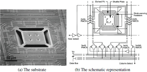
Figure 7.10. Single traction stress sensor consisting of a suspended plate/bridge structure with four embedded polysilicon resistors (Kane et al. 2000)
7.4. Haptic compression
The haptic data size can be reduced (compressed), like other types of data, such as multimedia content, for narrower transmission bandwidth. For example, lossless compression techniques such as Huffman can be applied, where the size of the haptic data is reduced without loss of information. However, this method is not efficient with regard to compression rate compared with the lossy compression algorithms. A subclass of the lossy method is based on humans’ perceptual capabilities, such as MP3 for audio or MPEG4 for video content compression. In these algorithms, not only the redundant information but also the irrelevant information is removed. For example, in the case of MP3, some information that cannot be perceived or only weakly perceived by the human ears is removed based on the human audio perception model. Lossy perceptual compression for haptic signals can also be applied in the same way as audio signals, based on a model of human haptic perception and exploits its limitations.
One constraint in haptic data compression is in the bidirectional telerobotic control system. The signal processing algorithm to implement the compression should be done in real time within <1 ms since the global control closed loop’s stability will be affected. This is in contrast to remote audio–video teleconferencing conversations, where the communications are twice unidirectional. Hence, audio and video signals can be compressed and sent without the need for the speaker, at one end, to listen to himself on the other end to control it, as shown in Figure 7.11.
Low-delay compression methods using differential pulse code modulation (DPCM) and adaptive DPCM with fixed and adaptive sampling frequency are presented and compared (Shahabi et al. 2002). In Guo et al. (2014), a linear prediction method is used by partitioning the haptic data samples into subsets based on knowledge from human haptic perception. The number of data subsets is then reduced using a prediction model. The predicted signal is derived such that it adapts itself to the local geometric changes of haptic signals. In their original work, Hinterseer et al. (2005) suggested a compression method based on the haptic discrimination bounds according to Weber’s law of JND. The haptic information is not sensed in this bound, and thus called the perceptual dead band (PD). Therefore, the transmission of one sample is enough to represent a packet of samples within the PD, as shown in Figure 7.12. In other words, once a new sample is measured and exceeds the threshold value ε of the haptic discrimination bound, a packet containing the latest measured haptic information h is sent. Around this value, a new threshold interval [h – ε, h + ε] is established, and only if a consecutive haptic sample lies outside this interval, a new packet is sent.
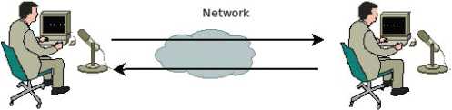
Figure 7.11. Conversation in a video teleconferencing is two times unidirectional. For a color version of this figure, see www.iste.co.uk/ali-yahiya/tactile.zip

Figure 7.12. Perceptual deadband compression. For a color version of this figure, see www.iste.co.uk/ali-yahiya/tactile.zip
This algorithm can be used for different haptic sensor data such as position, velocity and force.
To apply the PD method above in a multi-DoF telerobotic system, hi will become the new haptic sample to be compared with the previous in the Euclidean sense. If the distance ![]() then the new sample vector hi is transmitted. Otherwise, the new sample is discarded from the transmission (Kammerl 2012) as shown in Figure 7.13
then the new sample vector hi is transmitted. Otherwise, the new sample is discarded from the transmission (Kammerl 2012) as shown in Figure 7.13
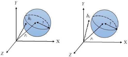
Figure 7.13. Multi-DoF isotropic perceptual dead band PD  , from (Kammerl 2012). For a color version of this figure, see www.iste.co.uk/ali-yahiya/tactile.zip
Additional methods can be used to predict new samples other than the simple sampling and hold described above. A first-order prediction can be used by taking two consecutive samples and finding a slope to be used in the prediction pi = hj+cj (i–j ), where cj is the slope of the line connecting the ith and jth samples, with i > j.
The value of the parameter k is an essential one in the quality of the compressed signal. As given in section 7.2.1, its range can vary a lot according to different research. Optimally, its value should be high enough for a better compression ratio and low enough for a better haptic sensation and consequently a transparent teleoperation system.
Other studies (Lee and Payandeh 2012) have suggested adaptive quantization using signal processing methods, and in the study by Mizuochi and Ohnishi (2013), a coding scheme using a low-pass filter and discrete Fourier transform was applied with reduced calculation cost and packet size.
The above-mentioned methods are convenient for transmitting haptic information for real-time applications such as telerobotics and telepresence. In some haptic applications where haptic data is recorded for a virtual environment, the compression algorithm speed is not an issue, for example, algorithms using discrete cosine transform (DCT) (Nakano et al. 2015) and model-based compression algorithms (Hinterseer et al. 2006).
The following section will find some works where the compression algorithm is used in the application layer of transmission protocols. This compression technique also uses Weber’s perception rule to sample higher or lower. This is the adaptive sampling in haptic applications, as suggested by Shahabi et al. (2001) and Otanez et al. (2002).
7.5. Haptic transport protocols
The transmission of haptic signals for teleoperation applications has specific needs such as reduced transmission delay and high transmission packet rate. Teleoperation applications mainly use the Internet as the medium of transmission in the absence and impracticality of dedicated wide area networks (WAN) for such applications. In order to achieve a good QoS in haptic signal transmission over the Internet and thus a good quality of experience (QoE) in the teleoperation applications, adapted transmission protocols should be used. These protocols should respect some QoS criteria and requirements. Table 7.2 from Kokkonis et al. (2018) shows the condition which the transmission media should respect to maximize the QoE of a haptic application.
Table 7.2. QoS requirement for different media streams (Kokkonis et al. 2018)
| QoS | Haptic | Video | Audio | Graphics |
|---|---|---|---|---|
| Jitter (ms) | ≤ 2 | ≤ 30 | ≤ 30 | ≤ 30 |
| Delay (ms) | ≤ 50 | ≤ 400 | ≤ 150 | ≤ 100 – 300 |
| Packet loss (%) | ≤ 10 | ≤ 1 | ≤ 1 | ≤ 10 |
| Update rate (Hz) | ≥ 1000 | ≥ 30 | ≥ 50 | ≥ 30 |
| Packet size (byte) | 64–128 | ≤ MTU | 160–320 | 192–5,000 |
| Throughput (kbps) | 512–1,024 | 25,000–40,000 | 64–128 | 45–1,200 |
To satisfy the requirement mentioned above, for haptic systems, the transmission system’s transport layer plays an important role. The protocols should then meet some constraints: the protocol should prioritize the real-time interactive data in multiplexing with audio and video signals. The protocols can moreover prioritize some essential samples of haptic information over others. A minimum overhead of transport protocol will allow a higher transmission rate. Concerning the jitter in reception and the congestion in the network, the protocol should pause transmission until the congestion is solved. Multiplexing and synchronizing different media streams with the haptic stream is another essential requirement for the transport protocol to obtain a good QoS.
Several protocols with some of the majority of the above requirements are suggested in the literature. Some of them are placed at the application layer, and others in the transport layer (Kokkonis et al. 2012). In the following section, we will give details about the properties of each of them.
7.5.1. Application layer protocols
The protocols in the application layer have the objective of customizing haptic communication protocols. This makes the protocol more agile. For example, a multi-modal or other additional information encapsulation is possible at this layer.
- – Application layer protocol for haptic networking (ALPHAN) (Osman et al. 2008): this protocol operates on top of the UDP since it does not impose any reliability or flow control schemes. The protocol supports the notion of key updates widely endorsed by most haptic communication transport layer protocols. This is done in the application layer by implementing a reliability mechanism applied to such updates, while regular updates remain unaffected. Figure 7.14 shows the header format of the protocol, with the frame field description in Table 7.3
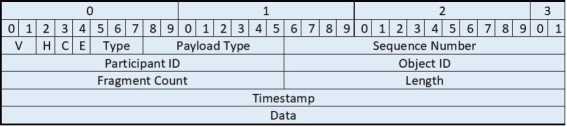
Figure 7.14. ALPHAN header format from Osman et al. (2008)
Table 7.3. Frame field description (Osman et al. 2008)
| Fields | Bits | Description |
|---|---|---|
| V | 2 | The version of the protocol; set to 0 for the current version |
| H | 1 | This bit is set if the data is haptic, and is reset if the data is graphic |
| C | 1 | Reporting collision state: the payload has position and force information if 1, position only if 0 |
| E | 1 | Not relevant for haptics. Indicate the last fragment of a packet for graphics data |
| Type | 3 | The type of haptic data: I, P, B frame and state query types for late comers |
| Payload type | 8 | Indicates single/multiple points of interaction for haptics and object types for graphics (rigid, deformable, etc.) |
| Sequence number | 16 | Identifies each packet and see if any packets were lost or delivered out of sequence |
| Participant ID | 16 | Identifies each participant in the C-HAVE environment. |
| Object ID | 16 | Identifies each object in the C-HAVE environment. |
| Fragment count | 16 | Not relevant for haptics. Identifies the number of fragments for graphic data |
| Length | 16 | Indicates the length of the payload |
| Timestamp | 32 | Time at which the event in the payload should be executed. Important for the implementation of a local lag mechanism |
Multiple buffering schemes are adapted in ALPHAN, where each haptic variable representing the environment is allocated a sending buffer. Two queues are arranged for each variable in case of retransmission to improve the application layer’s reliability since the UDP is not providing it. Another advantage of buffering is in prioritizing variables to be sent according to their importance.
The I packets are sent reliably and are considered to be key packets. P packets are encoded differentially based on previous I or P packets, while B packets are encoded based on previous and future I and/or P packets.
- – The synchronous collaboration transport protocol (SCTP) (Shirmohammadi and Georganas 2001): this is a host-to-host layer protocol, comparable to the transport layer. It is encapsulated into UDP packets and assumes that the underlying physical network supports IP multicasting. It was initially designed for interaction with a shared collaborative virtual environment. Figure 7.15 shows the packet format.

Figure 7.15. SCTP packet format
The protocol adopts the concept of reliable packet delivery of key updates and unreliable delivery of regular updates. The object ID indicates which object is being interacted in the header; the key update specifies if the packet is a key update or not. The stream ID and sequence number can be used together to discard late arriving messages. The protocol is inherently time-sensitive since updates are immediately taken into consideration.
Another version of this protocol called the smoothed SCTP has been devised by Dodeller (2004) to overcome the receiver’s jitter problem. A timestamp is added in the packet format. The time is divided into buckets of time of δt milliseconds at the receiver side. Each received update is put into a bucket according to its timestamp. A constant delay is added to the update; thus, all the update messages are processed with a fixed delay higher than the network delay, but constant.
- – Perception-based adaptive haptic communication protocol (PAHCP) (Nasir and Khalil 2012). In this protocol, the author devised a modified version of the smoothed SCTP and took into consideration extra features from other protocols such as reliable transmission protocol (SRTP), reliable multicast transport protocol (RMTP), synchronous collaboration transport protocol (SCTP) and selective reliable multicast (SRM). With a fixed threshold variable, Weber’s law is used to reduce the number of packets transmitted.
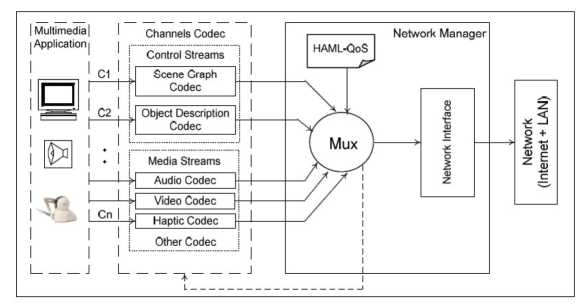
Figure 7.16. Communication framework (Eid et al. 2009)
- – ADMUX, Adaptive Multiplexer (Eid et al. 2011) is an adaptive application layer multiplexing framework including a communication protocol. It is designed for multimedia applications incorporating haptic, visual, auditory and scent data for non-dedicated networks. It uses statistical multiplexing to multiplex the different media. The statistical multiplexing principle is when a group of media channels shares a limited quantity of bandwidth. The allocation of bandwidth is on a frame-by-frame basis, which is controlled by the multiplexer. The multiplexer is based on a mathematical model that dynamically adapts to both the application needs and the network conditions (Eid et al. 2009). The haptic applications meta language (HAML) is used to initiate and functionally modify all the components of the communication framework as shown in Figure 7.16 (Eid et al. 2009). The components include:
- - the transport protocol, which defines the transport layer protocol, its reliability mechanism and its QoS parameters;
- - the synchronization scheme, which defines both the intermodal and intramodal synchronization models used in the communication;
- - the compression scheme, which defines the data preprocessing method (if used) and the codec configurations;
- - the control method scheme to describe the algorithms that are used at both ends of the network to compensate for the network deficiencies.
An advantage of the ADMUX is synchronizing haptic data with audio/video data and that it adapts to application level events and interactions.
- – RTP/I real-time application level protocol for distributed interactive media (Mauve et al. 2001): initially, this was developed to implement distributive interactive media such as remote collaborative whiteboards and 3D design applications. The protocol reuses some of the RTP properties, such as using two protocols, one for data and the other for control, called RTP/I and RTCP/I, respectively, both carried over separate transport addresses. The protocol relies on the exchange of state information modified by either events or the passage of time. The technical details of this protocol are given in the document (Mauve et al. 2000) and the web resource1.
- – Haptic over Internet protocol (HoIP) (Gokhale et al. 2013, 2015). In this protocol, adaptive sampling (from the highest haptic rate 1,000 packets/s to a minimum of 10 packets/s) of the haptic variables is implemented based on Weber’s law, where successive samples are compared to decide about the transmission or not of the new sample. HoIP uses the existing transport layer UDP for a better real-time performance and IP implementations. The frame of the HoIP protocol is shown in Figure 7.17. The fields of the frame are described in Table 7.4.
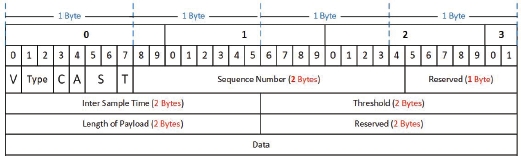
Figure 7.17. The frame of HoIP protocol (Gokhale et al. 2013). For a color version of this figure, see www.iste.co.uk/ali-yahiya/tactile.zip
7.5.2. Transport layer protocols
- – Interactive real-time protocol (IRTP): this is a transport layer protocol based on the IP; it is different from TCP and UDP but inherits their advantages (Ping et al. 2005). It is designed for interactive Internet-based service with a reduced end-to-end delay. It is a connection-oriented protocol, i.e. a connection must be established before transmitting data. This decreases its efficiency compared with connection-less protocols since in each connection some inquiry-reply happens before establishing a connection. But it has the advantage of managing the users and implementing reliable transmission since it is necessary. This protocol’s short header is shown in Figure 7.18 with the fields’ description given in Table 7.5.
The protocol interacts with the upper-layer protocol, in order to transmit both reliable and unreliable data. It distinguishes reliable transmission and unreliable transmission by the command segment in the header.
Table 7.4. HoIP frame description (Gokhale et al. 2013)
| Fields | Bits | Description |
|---|---|---|
| V | 1 | Protocol version set to 0 for haptic point-to-point communication (current implementation) |
| Type | 2 | Indicates type of the data. Set to 0 for haptics, 1 for haptics-audio, 2 for haptics-video, 3 for haptics-audio-video |
| C | 1 | Indicates content type of the payload. Set to 0 if only force coordinates are transmitted, 1 for position and velocity coordinates |
| A | 1 | Indicates the type of adaptive sampling employed. Set to 0 for Weber, 1 for level crossings. 1-bit is reserved for other samplers to evolve |
| S | 2 | Indicates transmission of threshold in the packet. Set to 1 if threshold is sent, else set to 0 |
| T | 1 | Identifier of each packet to track lost or out-of-order packets |
| Sequence number | 16 | Indicates the inter sample time gap. Along with the received times, this can be used to calculate packet delays |
| Inter sample time | 16 | Value of the threshold in percentage. If set to 0, data is transmitted at the haptic loop rate |
| Threshold | 16 | Indicates length of the payload |
| Length of payload | 16 | Not relevant for haptics. Identify the number of fragments for graphic data |

Figure 7.18. IRTP protocol header consisting of nine bytes
- – Real-time protocol (RTP) (Schulzrinne et al. 1996) This provides end-to-end network transport functions suitable for applications transmitting real-time data, such as audio, video or simulation data, over multicast or unicast network services. It was primarily designed to satisfy the needs for multiple-participant multimedia conferences. RTP is carried on top of IP and UDP, where an RTP header precedes a chunk of data; both are in turn contained in a UDP packet. For example, in audio signal transmission, the RTP header indicates the type of audio encoding (PCM, ADPCM or LPC). The RTP header contains timing information to reconstruct the timing produced by the source.
Table 7.5. IRTP header description
| Field | bits | Description |
|---|---|---|
| Command | 8 | 4 groups of commands: connection related commands, data sending and receiving related commands, inquiry commands and timer-related commands |
| Source identity | 16 | To identify the local port of a connection while the remote Port uses the 16 bits of identification segment of the IP header. |
| Sequence number or acknowledge number | 32 | A 32-bit number is assigned to each byte of its data. The sender sets this segment as the sequence number of the first byte |
| Checksum | 11 bytes | A 16-bit destination identity and 16-bit package length segment are added to the IRTP header and the checksum is calculated from it |
The RTP is used in conjunction with the real-time control protocol (RTCP) and is also needed to establish a multiuser conference, where each instance of the audio, video or any other application data periodically multicasts a reception report plus the name of its user on the RTCP (control) port. The reception report indicates how well the current data is being received and may be used to control adaptive encodings. Other identifying information may also be included in this protocol subject to control bandwidth limits, such as the inter-arrival jitter estimate, information about the highest sequence number received, a fraction of packets lost and a cumulative number of packets lost.
- – The stream control transmission protocol (SCTP) is a general-purpose transport layer protocol. The services it provides are similar to TCP and a set of advanced features (Stewart 2007) to use the enhanced capabilities of modern IP networks and support increased application requirements.
- – The efficient transport protocol (ETP) (Wirz et al. 2008) is a transport layer protocol that optimizes the available bandwidth by sending the highest packets with a reduced round trip time (RTT) and the time between two packets’ inter-packet gap (IPG). It is designed for haptic applications to integrate the good characteristics of many other transport protocols. The protocol’s performance is based on reducing the IPG to reduce the RTT, which represents the frequency of closing the control loop of the remote haptic system RTT = IGP.N, where N is the sum of the number of sent and received packets through the network, ETP uses the UDP protocol for transporting its data.
- – Real-time network protocol (RTNP) (Uchimura and Yakoh 2004): this is specially designed for bilateral teleoperation using master/slave manipulators and force feedback. It is specially designed for the UNIX environment. Its priority determines each packet order in a queue at the sender and the intermediate buffers over the network.
- – Bidirectional transport protocol (BTP) provides a novel congestion control technique that enhances application and transport layer performance (Wirz et al. 2009). The protocol improves bilateral flow tasks for real-time telerobotics by minimizing the round trip time (RTT) while maximizing the transmission frequency. To do this, the network congestion is controlled by modifying the elapsed time between two consecutive packets sent: Inter-Packet Gap (IPG) . IPG is related to the interarrival time (IAT), which is the time elapsed between two consecutive arriving packets. Both are related and equal in the case of no congestion. The BTP packet information is shown in Figure 7.19, where it is shown that it uses the UDP protocol with an additional header of the BTP.

Figure 7.19. BTP packet information
7.6. Multi-transport protocols
Some protocols, as shown above, multiplex different media streams before transmitting them all in one protocol. Another way to send other data streams is to send them on multiple protocols according to their characteristics. For example, slow data with reliable communication requirements can be sent on a TCP protocol, while a control signal can be sent on a UDP and video or audio on an RTP. In Phung et al. (2012), the authors suggested the above multi-transport protocol in the remote control and monitoring of a mobile robot.
7.7. Haptic transport protocol performance metrics
The main performance metrics for haptic transport protocols are returned delay time, packet loss, jitter (varying time delay) and throughput. As was shown in Chapter 6, the constant delay in the network can be handled from the stability point of view. However, the variable delay causes system instability.
7.8. Conclusion
The compression and transmission of haptic data over a telepresence application network have different requirements and constraints from the other media-type signals such as audio and video. The samples of audio and video signals can be processed in packets and reduced in size using compression. The principle of perceptual predictive haptic data compression consists of two key components:
- – a psychophysical model deployed at the encoder;
- – signal predictors which are used at the encoder and the decoder.
The prediction algorithm estimates incoming haptic samples based on previously transmitted haptic data. Both predictors at the encoder and the decoder run in parallel and are fed with identical signal information to keep them strictly coherent. The psychophysical model of human haptic perception suitable for haptic real-time communication can be built based on Weber’s law of JND. A signal prediction algorithm estimates future haptic samples based on previous signal input. For the prediction of haptic signals, typically linear predictors of a very low order and low latency are required.
Many protocols have been tried and suggested to transmit haptic information with its specific temporal and bandwidth requirements. Some protocols multiplex and synchronize haptic data with other types of media such as audio and video.
7.9. References
Adelstein, B.D. and Rosen, M. (1992). Design and implementation of a force reflecting manipulandum for manual control research. ASME Winter Annual Meeting, pp. 1–12.
Amato, M., Vittorio, M.D., Petroni, S. (2013). Advanced MEMS technologies for tactile sensing and actuation. MEMS Fundamental Technology and Applications. CRC Press, Boca Raton.
Arimoto, S., Ozawa, R., Yoshida, M. (2005). Two-dimensional stable blind grasping under the gravity effect. Proceedings of the 2005 IEEE International Conference on Robotics and Automation, pp. 1196–1202.
Bejczy, A.K. (1980). Sensors, controls, and man-machine interface for advanced teleoperation. Science. 208(4450), 1327–1335.
Chuang, C.H., Weng, H.K., Chen, J.W., Shaikh, M.O. (2018). Ultrasonic tactile sensor integrated with TFT array for force feedback and shape recognition. Sensors and Actuators A: Physical, 271, 348–355 [Online]. Available at: http://www.sciencedirect.com/science/article/pii/S0924424717317612.
Dahiya, R.S. and Valle, M. (2013). Robotic Tactile Sensing Technologies and System. Springer, Dordrecht.
Dodeller, S. (2004). Transport layer protocols for telehaptics update messages. Proceedings of the 22nd Biennial Symposium on Communications.
Eid, M., Cha, J., El Saddik, A. (2009). An adaptive multiplexer for multi-modal data communication. 2009 IEEE International Workshop on Haptic Audio Visual Environments and Games, pp. 111–116.
Eid, M., Cha, J., El Saddik, A. (2011). Admux: An adaptive multiplexer for haptic audio visual data communication. IEEE Transactions on Instrumentation and Measurement, 60(1), 21–31.
ESA (2014). Exoskeleton to remote control robot live [Online]. Available at: https://www.esa.int/Science_Exploration/Human_and_Robotic_Exploration/Exoskeleton_to_remote-control_robot_live.
Goger, D., Gorges, N., Worn, H. (2009). Tactile sensing for an anthropomorphic robotic hand: Hardware and signal processing. 2009 IEEE International Conference on Robotics and Automation, pp. 895–901.
Gokhale, V., Dabeer, O., Chaudhuri, S. (2013). Hoip: Haptics over internet protocol. 2013 IEEE International Symposium on Haptic Audio Visual Environments and Games (HAVE), pp. 45–50.
Gokhale, V., Chaudhuri, S., Dabeer, O. (2015). Hoip: A point-to-point haptic data communication protocol and its evaluation. 2015 Twenty First National Conference on Communications (NCC), pp. 1–6.
Guo, F., Zhang, C., He, Y. (2014). Haptic data compression based on a linear prediction model and quadratic curve reconstruction. Journal of Software, 9(11), 2796–2803.
Heo, J.S., Chung, J.H., Lee, J.J. (2006). Tactile sensor arrays using fiber bragg grating sensors. Sensors and Actuators A: Physical, 126(2), 312–327 [Online]. Available at: http://www.sciencedirect.com/science/article/pii/S0924424705006084.
Hinterseer, P., Steinbach, E., Hirche, S., Buss, M. (2005). A novel, psychophysically motivated transmission approach for haptic data streams in telepresence and teleaction systems. Proceedings (ICASSP ’05). IEEE International Conference on Acoustics, Speech, and Signal Processing, 2, ii/1097–ii/1100.
Hinterseer, P., Steibach, E., Chaudhuri, S. (2006). Model based data compression for 3D virtual haptic teleinteraction. 2006 Digest of Technical Papers International Conference on Consumer Electronics, pp. 23–24.
Inoue, T. and Hirai, S. (2014). Why humans can manipulate objects despite a time delay in the nervous system. In The Human Hand as an Inspiration for Robot Hand Development, Balasubramanian, R., Santos, V.J. (eds). Springer, Springer International Publishing Switzerland, Cham.
Loomis, J.M. and Lederman, S.J. (1986). Tactual perception. In Handbook of Human Perception and Performance, Boff, K.R., Kaufman, L., Thomas, J.P. (eds). John Wiley & Sons, Hoboken, NJ.
Kammerl, J. (2012). Perceptual haptic data communication for telepresence and teleaction. PhD Thesis, Technische Universität München, Munich.
Kane, B.J., Cutkosky, M.R., Kovacs, G.T.A. (2000). A traction stress sensor array for use in high-resolution robotic tactile imaging. Journal of Microelectromechanical Systems, 9(4), 425–434.
Kappassov, Z., Ramon, J.A.C., Perdereau, V. (2015). Tactile sensing in dexterous robot hands – Review. Robotics and Autonomous Systems, hal-01680649, 74, 195–220.
Kokkonis, G., Psannis, K.E., Roumeliotis, M., Kontogiannis, S., Ishibashi, Y. (2012). Evaluating transport and application layer protocols for haptic applications. 2012 IEEE International Workshop on Haptic Audio Visual Environments and Games (HAVE 2012) Proceedings, pp. 66–71.
Kokkonis, G., Psannis, K.E., Kontogiannis, S., Nicopolitidis, P., Roumeliotis, M., Ishibashi, Y. (2018). Interconnecting haptic interfaces with high update rates through the internet. Applied System Innovation, 1(4) [Online]. Available at: https://www.mdpi.com/2571-5577/1/4/51.
Lee, M.H. and Nicholls, H. (1999). Tactile sensing for mechatronics a state of the art survey. Mechatronics, (9), 1–21.
Lee, J. and Payandeh, S. (2012). Signal processing techniques for haptic data compression in teleoperation systems. 2012 IEEE Haptics Symposium (HAPTICS), pp. 371–376.
Lowe, D.G. (1999). Object recognition from local scale-invariant features. Proceedings of the Seventh IEEE International Conference on Computer Vision, 2, pp. 1150–1157.
Lucia, S., Paolo, G., Watt, S.J., Valyear, K.F., Zuher, F., Fulvio, M. (2019). Active haptic perception in robots: A review. Frontiers in Neurorobotics, 13, 53 [Online]. Available at: https://www.frontiersin.org/article/10.3389/fnbot.2019.00053.
Luo, S., Bimbo, J., Dahiya, R., Liu, H. (2017). Robotic tactile perception of object properties: A review. Mechatronics, 48, 54–67.
Malley, M.K.O. and Gupta, A. (2008). Haptic interfaces. In HCI Beyond the GUI: Design for Haptic, Speech, Olfactory, and Other Nontraditional Interfaces, Kortum, P.. Morgan Kaufmann, Amsterdam.
Mauve, M., Hilt, V., Kuhmünch, C., Vogel, J., Geyer, W., Eefflsberg, W. (2000). RTP/I: An application level real-time protocol for distributed interactive media [Online]. Available at: https://wwwcn.cs.uni-duesseldorf.de/publications/publications/library/Mauve2001a.pdf.
Mauve, M., Hilt, V., Kuhmunch, C., Effelsberg, W. (2001). RTP/I-toward a common application level protocol for distributed interactive media. IEEE Transactions on Multimedia, 3(1), 152–161.
Millman, P.A. and Colgate, J.E. (1991). Design of a four degree-of-freedom force-reflecting manipulandum with a specified force/torque workspace. Proceedings 1991 IEEE International Conference on Robotics and Automation, 2, 1488–1493.
Minsky, M.D.R. (1995). Computational haptics: The sandpaper system for synthesizing texture for a force-feedback display. PhD Thesis, MIT Press, Cambridge, MA.
Mizuochi, M. and Ohnishi, K. (2013). Optimization of transmission data in bilateral teleoperation. The Transactions of the Institute of Electrical Engineers of Japan, 133(3), 314–319.
Nakano, T., Uozumi, S., Johansson, R., Ohnishi, K. (2015). A quantization method for haptic data lossy compression. 2015 IEEE International Conference on Mechatronics (ICM), pp. 126–131.
Nasir, Q. and Khalil, E. (2012). Perception based adaptive haptic communication protocol (PAHCP). 2012 International Conference on Computer Systems and Industrial Informatics, pp. 1–6.
Nitsch, V., Kammerl, J., Faerber, B., Steinbach, E. (2010). On the impact of haptic data reduction and feedback modality on quality and task performance in a telepresence and teleaction system. International Conference on Human Haptic Sensing and Touch Enabled Computer Applications. Springer, Berlin, Heidelberg.
Ohka, M. (2007). Optical three-axis tactile sensor. Mobile Robots: Perception and Navigation. IntechOpen, London.
Osman, H.A., Eid, M., Saddik, A.E. (2008). Evaluating alphan: A communication protocol for haptic interaction. 2008 Symposium on Haptic Interfaces for Virtual Environment and Teleoperator Systems, pp. 361–366.
Otanez, P.G., Moyne, J.R., Tilbury, D.M. (2002). Using deadbands to reduce communication in networked control systems. Proceedings of the 2002 American Control Conference (IEEE Cat. No.CH37301), 4, 3015–3020.
Parkes, A., Poupyrev, I., Ishii, H. (2008). Designing kinetic interactions for organic user interfaces. Communications of the ACM, 51(6), 58–65.
Phung, M.D., Tran, T.H., Van Thi Nguyen, T., Tran, Q.V. (2012). Control of internetbased robot systems using multi transport protocols. 2012 International Conference on Control, Automation and Information Sciences (ICCAIS), pp. 294–299.
Ping, L., Wenjuan, L., Zengqi, S. (2005). Transport layer protocol reconfiguration for network-based robot control system. Proceedings. 2005 IEEE Networking, Sensing and Control, pp. 1049–1053.
Robertson, B.E. and Walkden, A.J. (1985). Tactile sensor system for robotics. Measurement and Control, 18(7), 262–265 [Online]. Available at: https://doi.org/10.1177/002029408501800703.
Rossi, D.D. (1991). Artificial tactile sensing and haptic perception. Measurement Science and Technology, 2(11), 1003–1016 [Online]. Available at: https://doi.org/10.1088/0957-0233/2/11/001.
Schiele, A. (2014). An exoskeleton to remote-control a robot tedxrheinmain [Online]. Available at: https://www.youtube.com/watch?v=JvAho9tym4A.
Schmidt, R.F. (ed.) (1986). Somatovisceral sensibility. Fundamentals of Sensory Physiology, Springer, Berlin, Heidelberg.
Schulzrinne, H., Casner, S., Frederick, R., Jacobson, V. (1996). RTP: A transport protocol for real-time applications. Report, RFC 1889.
Shahabi, C., Kolahdouzan, M.R., Barish, G., Zimmermann, R., Yao, D., Fu, K., Zhang, L. (2001). Alternative techniques for the efficient acquisition of haptic data. SIGMETRICS Performance Evaluation Review, 29(1), 334–335.
Shahabi, C., Ortega, A., Kolahdouzan, M.R. (2002). A comparison of different haptic compression techniques. Proceedings of the IEEE International Conference on Multimedia and Expo, 1, pp. 657–660.
Shirmohammadi, S. and Georganas, N.D. (2001). An end-to-end communication architecture for collaborative virtual environments. Computer Networks, 35(2), 351–367 [Online]. Available at: http://www.sciencedirect.com/science/article/pii/S1389128600001869.
Stewart, R. (2007). Stream Control Transmission Protocol. Proposed standard, RFC 4960, September.
Sutherland, I.E. (1965). The ultimate display. Proceedings of the IFIP Congress, pp. 506–508.
Torres-Jara, E., Vasilescu, I., Coral, R. (2006). A soft touch: Compliant tactile sensors for sensitive manipulation. Technical Report MIT-CSAIL-TR-2006-014, Massachusetts Institute of Technology’s CSAIL, Cambridge, MA.
Uchimura, Y. and Yakoh, T. (2004). Bilateral robot system on the real-time network structure. IEEE Transactions on Industrial Electronics, 51(5), 940–946.
Wirz, R., Ferre, M., Marín, R., Barrio, J., Claver, J., Ortego, J. (2008). Efficient transport protocol for networked haptics applications. Haptics: Perception, Devices and Scenarios, Lecture Notes in Computer Science, vol. 5024, Springer, Berlin, Heidelberg.
Wirz, R., Marin, R., Ferre, M., Barrio, J., Claver, J.M., Ortego, J. (2009). Bidirectional transport protocol for teleoperated robots. IEEE Transactions on Industrial Electronics, 56(9), 3772–3781.
Xie, Y., Chen, C., Wu, D., Xi, W., Liu, H. (2019). Human-touch-inspired material recognition for robotic tactile sensing. Applied Sciences, 12, 2537.
Zhang, H. and So, E. (2002). Hybrid resistive tactile sensing. IEEE Transactions on Systems, Man, and Cybernetics, Part B (Cybernetics), 32(1), 57–65.