
8
Mapping Wireless Networked Robotics into Tactile Internet
Nicola Roberto ZEMA and Tara ALI-YAHIYA
Department of Computer Science, University of Paris-Saclay, France
A set of robots whose functionalities as a whole and as single elements are enhanced and enabled by wireless networking is called a Robotic Network and enclosed in the framework of Wireless Networked Robots (WNR). In this kind of network, the nodes need to exchange a large set of different types of data, ranging from positional information to large chunks of sensor data and even high quality video. The data also has to be delivered inside the temporal limits associated with the robotic control algorithms.
As the Tactile Internet (TI) is one of the few standards that considers the delivery of kinesthetic and large-bandwidth data among distant entities and inside strict temporal limitations, it is possible to map Wireless Networked Robots inside the Tactile Internet Architecture and Interfaces. This chapter deals with the aforementioned integration by first characterizing Wireless Networked Robots, describing the traffic generated by this kind of network and then translating the requisites, scenarios and uses cases into the Tactile Internet.
8.1. Wireless networked robots
It is possible to define Networked Robotics as a system of systems that has autonomous capabilities and network-based cooperation. The autonomous capability refers to the possibility for a system element to move and interact within and with its surrounding physical environment, and the network-based cooperation consists of the global system’s extreme dependency on communications, within its composing elements, to operate.
A set of robots displaying these characteristics form a Robotic Network, a subset of Sensor and Actuator Networks (SANs). With respect to SANs, RNs have the added features of degrees of mobility and are generally described as an ensemble, a fleet or a swarm. The need to be mobile and the constraints therein almost automatically mean Wireless Networking is almost the only possible choice for Networked Robotics, thus transforming them to Wireless Networked Robots. The definition has come a long way and it can be traced back to the IEEE Technical Committee (Isler et al. 2015) that was originally created for Internet-teleoperated robots and came to include Robotic Networks and Cloud Robotics. Even though the standard did not define them yet, usually the general architecture of WNRs includes a set of entities external to the robot fleet: a Remote Station. The Remote Station is the pivot point between the robots and the external world. The robots send their data to this station and can receive tasks, command and situational updates from it. The communication between the set of robots and the station is usually delegated to a set of gateway robots. These robots collect and manage the traffic from their peers and can relay it to the Remote Station.
An interesting example of WNR is a coordinated fleet instructed to film a sporting event (Natalizio et al. 2019). Starting from the case where a single UAV is being remotely operated to film the sport event, the scenario is expanded with first a fleet of independent UAVs, then with a UAV fleet whose elements share their pose and status, and then with the capability to relay the videos to each other, as shown in Figure 8.1. Finally, the following features are added. Each UAV is capable of:
- – identifying the areas of interest to be filmed automatically;
- – placing itself in order to always be ready to reach the closest areas of interest;
- – placing itself in order to maximize the quality of the video being relayed to a remote element.
From the case where a single UAV is remotely operated, the importance of networking is increased manyfold as the communications between the robots becomes integral to the system functioning and the network parameters are involved in the algorithms that permit the advanced capabilities.
By considering WNRs as a whole there is a slight paradigm shift in the research focus. From considering the single-robot as the highest hierarchical element of the possible frameworks, now it has become one of the component elements of the ensemble, fleet or swarm. Historically, the research focus has been on how to introduce coordination and cooperation, among the component robotic elements, in terms of movement algorithms, task allocation problems and formation coordination, just to cite a few. However, the approach has almost always been to consider the networking part of WNRs as the set of constraints to adhere to or the problem to overcome. Even with the advent of Controlled Mobility (Kansal et al. 2004; Natalizio and Loscrí 2013; Zema et al. 2016), there is still no strict definition of what the expected traffic within WNRs is, how to classify and how to treat it.

Figure 8.1. A subset of two robots in a WNR that is used to relay the video of a sporting event to a spectator too far away to receive it in HD from the filmer UAV using a second one, a relayer. The filmer UAV is capable of tracking the sporting event and the relayer UAV is capable of placing itself in a position to relay the video, in HD, to all the spectators on its side. For a color version of this figure, see www.iste.co.uk/ali-yahiya/tactile.zip
In this chapter, we propose to invert the trend, define the WNR traffic features in strict terms and then place them within the framework of the Tactile Internet. This, in turn, will give researchers and implementers the possibility to use WNRs and their networking as a dimension in their works rather than a hard limitation.
The hard constraints of TI traffic classes and Key Performance Indicators specifically constructed for kinesthetic control and remote operation are excellent candidates to be transposed to the world of WNRs. The short delays and low error rates necessary in the Tactile Internet are similar to the ones needed for the coordination of distant robots moving autonomously.
This chapter is subdivided as follows. Section 8.2 describes a new use case in TI for WNRs and describes the kinds of network traffic in WNRs. Section 8.3 focuses on defining the KPIs of the main traffic type of WNRs. Section 8.4 uses the WNR KPIs to map the WNR elements into the TI architecture and interfaces and, finally, section 8.5 concludes the chapter.
8.2. WNR traffic requisites
The Tactile Internet is defined by a standard (Holland et al. 2019) that, in turn, defines a set of use cases and related networking constraints. The most relevant to the WNR world are as follows:
- 1) teleoperation;
- 2) automotive;
- 3) Internet of Drones;
- 4) cooperative automated driving;
- 5) interpersonal communications.
However, none of these fully encompass the specificities of WNR. First, the strict separation of master and slave in the first four use cases does not adapt well to each robot in WNRs being both a sink and a source of data at the same time, summarized in use case 5 (interpersonal communication), that in turn does not have the specificities of other cases.
It is then necessary to define a new use case specific for WNRs by first taking into account the specific traffic generated and consumed by them.
8.2.1. Types of traffic in WNRs
WNRs need specific care as, intrinsically, they include two broad categories of traffic:
- – data traffic;
- – control traffic.
Data traffic can be broadly characterized as the data necessary or produced for and by the application or task the robots are running. An example is the audio feed collected by an underwater robot’s sonar that is transmitted back to a remote station or the Internet traffic of a mobile cellular repeater mounted on a UAV. Control traffic on the other hand is the traffic necessary to the inner working of the WNR, like the telemetry data for reciprocal distance estimation in a robotic fleet or the flying control commands for the leader in a UAV swarm. Given their features, it is necessary to treat them differently and separately as they do have different specificities.
A significant example that can be used to illustrate these different specificities can be found in a Mobile Cellular Infrastructure scenario (Boss et al. 2016; Jalali 2018; Fotouhi et al. 2019). In this scenario, a fleet of UAVs carrying cellular equipment is dispatched and dispersed in an area with the task to cover it. As shown in Figure 8.2, by covering we mean that the robots have to displace themselves in order to, at the same time, (i) cover the entire area with the combination of their cellular transceiver communication ranges and (ii) remain in relative contact in order to relay the user data on the ground to each other and then to a gateway element, connected to the backbone, by moving inside limited areas according to a set of algorithms.
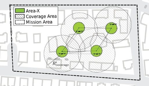
Figure 8.2. Example of a WNR for Mobile Cellular Infrastructure inside its Mission Area. The single UAV with its Ricoverage tries to maximize the fleet Coverage Area by moving inside Area-X while still keeping the formation. For a color version of this figure, see www.iste.co.uk/ali-yahiya/tactile.zip
8.2.1.1. Data
Data traffic refers to the traffic generated by or by virtue of the application running on the networked robots. When the fleet is given a task alongside an application, the data related to the task execution is the data traffic. In the example scenario, the user traffic coming from the backbone to the users on the ground, and vice versa, is the data traffic. Although important as a payload, it has almost no direct effect on the fleet operation and it can be physically separated. However important and subject to different shaping and restrictions (phone calls vs. best effort Internet traffic), failures in data traffic delivery do not jeopardize fleet and robot operations. In general, it is not possible a priori to characterize this traffic as it is application dependent. It is, however, possible to provision it using the application specifications.
8.2.1.2. Control
Control traffic refers instead to the traffic generated by and from the actual fleet and its component elements. The message that concerns task assignment to a specific robot, its feedback, formation coordination and robot remote operation makes up the control traffic.
In the example scenario, when the UAVs enter the area, they are dispatched to specific locations. This dispatch can come from a centralized entity or even by the fleet self-organizing after a local survey. In whichever case, the robots need to communicate with each other or with a distant entity in order to know where to go. In some cases, each robot can perform an area survey and send its data elsewhere to be computed to adjust fleet operation. This is the control traffic. Different from the data traffic, failures in the control traffic do jeopardize fleet and robot operations and thus the whole traffic category has to be treated differently.
As the robot operation is supposed to be autonomous, in the specific case of WNRs, the remote operation of robots is considered to be handled at application level and thus can be deemed part of the data traffic.
Control traffic can instead be enclosed in more strict terms. It is possible to classify it into the following sub-categories:
- – inertial kinesthetic (pose and velocity);
- – absolute positioning (GPS, GLONASS, Galileo);
- – low-frequency sensors (fixed imagery, compressed sensory data);
- – high-frequency sensors (LIDAR, RADAR, video imaging, audio capture).
8.3. Traffic shaping and TI haptic codecs
To treat traffic differently, it is necessary to define a way to identify it and then to apply discriminating actions to the identified parts. Given that in general the WNR traffic will lie on an IP basis, it is likely that the already established mechanisms for IP traffic shaping will be put in place, and these are summarized in the Service-Level Agreements of the Quality of Service paradigm applied to the component networks of the whole WNR. However, there is no SLA definition for WNRs as the work of the related IEEE Technical Committee has not progressed further. In this chapter, we thus propose to define the WNR traffic in terms of TI infrastructure and codes, in order to map the necessities of WNRs in an already existing established framework. TI has been chosen as it is the only one that combines either low-latency, strictly high-latency traffic and high bandwidth in a single set of definitions.
8.3.1. Introduction
Different, however, from the standard TI use cases, for WNRs there is an added challenge: the presence, at the same time, of prioritized traffic for general operation and prioritized payload (the data traffic).
Referencing the mobile cellular station scenario previously introduced in section 8.2.1, hierarchies can be defined inside control traffic, where inter-robot telemetry traffic has priority over remote operation traffic, going out to the backbone to a remote server, that in turn has priority over low-rate traffic that is used, for instance, in the algorithms for fleet maintenance. Inside the data traffic, more classic hierarchies can be maintained, with tolled phone calls having precedence over best-effort Internet.
Lots of questions arise at this point such as if it is necessary to include all the hierarchies together or if it is better to separate them and leverage physical layer separation where available.
Different strategies could be put into operation. One of them is to treat control traffic as always having higher priority over data traffic. Another is to carefully optimize interleaving traffic and control on a per-scenario basis. A third solution would be to define novel algorithms and solutions that are capable of dynamically changing priorities according to the environment. In any case, this research line is outside the scope of this work, that is the preliminary step of defining these traffic classes and their sub-classes.
8.3.2. Mapping WNR control traffic to TI
The first step of this analysis is to clearly define the WNR control traffic. As previously defined in section 8.2.1.2, control traffic can be subdivided into sub-categories that collect together functionalities with the same requirements.
8.3.2.1. Kinesthetic/inertial and absolute positioning
The first and maybe most important traffic class is the one that carries inertial/kinesthetic information. The mobility is the most important degree of freedom in WNRs and thus follows that information regarding this is to be treated with the highest reliability and speed. In the cases where the piloting is done remotely either with a human-in-the-loop (remote piloting) or machine-in-the-loop (remote formation control), it is necessary that updates in robot position and velocity are relayed to a given entity with the minimum possible tolerance. Failure to do so could well result in equipment damage and divergence in maintenance algorithms. Thus, in these cases, the traffic carrying this information would need the highest priority class. Even when the piloting is completely autonomous, it is still necessary to share, among the robots, the information about pose and velocity to run, for instance, keeping formation. This case is also exemplary for another requirement: the link bidirectionality. Not only does a robot send data outside, but it is expected to receive navigational commands or even direct inputs to its control loop. In any case, the highest environmental dynamicity is expected. According to Matheus and Königseder (2017), the necessary bandwidth is narrow and is dependent of the degrees of freedom involved. The subclass is called inertial as the data is generated, for each robot, by its own instruments and internal navigation systems (inertial measurement unit, altimeter) and it is differentiated by the data generated by absolute positioning systems (GPS, GLONASS and Galileo). This is due to the update frequencies of absolute positioning being different, and lower, from the inertial ones. Furthermore, absolute positioning could not always be present and active all the time. In the following table, it is possible to sample the traffic features.

8.3.2.2. Low-frequency sensors
With the WNR algorithms becoming increasingly complex, they often need more information than kinesthetic data. An underwater robot exploring a cave could use a SONAR system to scan its surroundings. If the robot is located at the end of a chain of other robots that relay communications to a distant station, it could also send the sonar imagery to the station. In respect to the previous sub-category, the traffic that carries the imagery has a greater bandwidth and also a slightly lower reliability limit. The sonar images are generated periodically, they do not constitute a constant stream, and they can be compressed and passed through an error correction algorithm. A whole broad category of information falls within these boundaries and includes, for instance, samples of connected users (and their statistics) in the mobile cellular station scenario or samples of detected chemical data when UAVs are used to survey pollutants. Robots can also be consumers of this kind of traffic. WNR algorithms could include fog or even local-based computational distribution, and thus, the traffic is always bidirectional: in the underwater robot scenario, the robots could share the SONAR information and cooperate computationally to apply filters and analysis to the imagery. This traffic can be assimilated to the one often common in vehicular networks and, specifically, in scenarios of low or absent dynamicity. In this case, the following table can be used as a reference (Cao et al. 2016; Campolo et al. 2017), where the traffic is further subdivided into low-frequency video, that includes image compression algorithms, and low-frequency aggregate, for uncompressed data.
8.3.2.3. High-frequency sensors
WNRs can also rely on direct computation of video data to run the algorithms (Natalizio et al. 2019), and there are cases where high-bandwidth data analysis is put inside the robot control loop. For instance, in a distributed UAV surveillance scenario, the robots are dispersed over an area and capture video that is then distributed to the WNR component for cooperative evaluation. The video quality, in terms of perceptive metrics like PSNR, is used to tune target network parameters like jitter and latency between the video source and its sink. As the scenario is a wireless one, these parameters are then translated into a set of constraints on the robot’s relative positions. It then forms a closed control loop that involves robot positioning and video quality. The same reasoning could be applied to a high-frequency sonar feed in an underwater exploration scenario. High-bandwidth flows have different features with respect to the other cases, that translate into even more stringent limitations when it is necessary to maintain bidirectionality of links. In a distributed surveillance scenario robots could cooperate in the video analysis to detect intrusion without relying on external computation resources and the WNR should be capable of sharing the video feed among robots (Muzaffar et al. 2020; Marshall et al. 2008). Based on these features, the following table can be composed, where for flying robots even more stringent boundaries are set, to take into account the increased environmental dynamicity.

8.3.2.4. Tactile Internet codec translation
The TI task subgroup group IEEE 1918.1.1 (Steinbach et al. 2018) is bound to define the codecs for the proposals. In this case, the codecs correspond to the definitions of network-side support for the TI. Two main codec categories are identified: tactile and kinesthetic and the stated objective is to reduce the average packet rate in haptic communications in order to make the two endpoints of a Tactile Internet communication appear to be locally available even in the presence of delays.
The tactile codecs correspond to the encoding and transfer of the information related to human perception of touch while the kinesthetic codecs are related to the information about limb movement in humans.
The kinesthetic codecs are of great importance for WNRs as the kinesthetics referred to overlaps with the kinesthetic/inertial information referred to in section 8.3.2.1. Even though the standard does not yet fully define the codecs, an important groundwork has been laid in identifying classes of traffic and the way they should be treated. The standard divides the codecs into delay-tolerant and delay-intolerant ones. This difference stems from the fact that it is necessary to put in place a stabilizing control mechanism when in the presence of significant delays, usually more than 5 ms. When the expected or detected latency is below the threshold, then the delay-intolerant codecs are run, to compress the transmitted information and reduce the number of exchanged packets in the network. When the latency is above the threshold, then the objective is to stabilize the system. The investigated alternatives so far include:
- – algorithms that exploit the human perception of kinesthetic stimuli (Weber’s law (Culbertson et al. 2014));
- – algorithms based on data reduction.
In WNRs, Weber’s law algorithms need to be carefully analyzed before being adopted as they are designed for anything other than machine-in-the-loop systems and the data reduction algorithms show performance degradation when used in highly dynamic environments (Steinbach et al. 2018).
For these difficulties, to date, kinesthetic codecs have been explored but not yet defined in the standard and delay compensation mechanisms are of great interest for WNRs.
More important than delay is the loss compensation. In the wireless networks provisioned, loss probabilities are non-negligible and mechanisms need to be put in place to compensate for message losses. An example of compensation mechanism (in this case, for the packet loss) is described in Manfredi et al. (2020). In this case, a layer of redundancy is added in the packet flow that handles the formation control of an UAV fleet to take into account possible burst losses.
8.4. WNRs in the Tactile Internet architecture
According to the previous sections is it now possible to define a new TI use case for WNRs and populate it with a set of KPIs. One of the most striking features with respect to the other use cases is that in WNRs the traffic and the TI encasing it is bidirectional. It has to be provisioned that each robot could communicate with any of its peers via a TI set of interfaces. Table 8.1 summarizes the use case.
Table 8.1. WNR use case for TI features
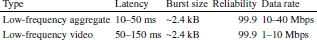
| Type | Latency | Burst size | Reliability | Data rate |
|---|---|---|---|---|
| Kinesthetic/inertial | 1–10 ms | 2–8B ∀ DoF | 99.999 | 1–4 kpkt/s |
| Absolute positioning | 30–40 ms | 2kB | 99.9 | 5–512 kbps |
| Low–frequency aggregate | 10–50 ms | ~2.4kB | 99.9 | 10–40 Mbps |
| Low-frequency video | 50–150 ms | ~2.4kB | 99.9 | 1–10 Mbps |
| UAVs HD video | 10–100 ms | ~2.4kB | 99.9 | 1–100 Mbps |
| Robot high frequency | 30–40 ms | 4kB | 99.999 | 1–10 Mbps |
The KPIs can then be used to map WNRs into the TI framework interface features and architecture.
8.4.1. WNRs in the TI architecture and interfaces
Tactile Internet architecture defines a set of entities and interfaces that are connected together and evaluated with a set of KPIs described by the use case the TI is deploying at that moment. After having translated the WNR traffic requirement into a set of KPIs, it is now possible to use them to map the WNR into the TI architecture and interfaces, translating each part of the WNR into the most appropriate part of TI. To better present the mapping, it is possible to leverage again the Mobile Cellular Infrastructure scenario of section 8.2.1 and shown again in Figure 8.3. In this scenario, a set of UAVs, a swarm, is dispatched to distribute itself in a given area where mobile users are located. The UAVs carry three network interfaces:
- – a portable cellular base station that has its own range;
- – a network interface for the UAVs to relay the mobile user data;
- – a network interface for the WNR operation.
It also deploys an intermediate station, i.e. the UAV carrier, a local base station, that is in communication, at the same time, with the UAVs, or a subset of them, and with a remote base station using a long-range link.
For the moment, we focus on the WNR operation and suppose that the user data, the data traffic of section 8.2.1.1, is outside the scope of this chapter. While not using the same frequencies and technologies, the UAVs could leverage the presence of the intermediate station to reach the remote base station for the data traffic. In any case, it is necessary to at least provision the interfaces for just the control traffic and then add on top on them the per-application requirements of the data traffic.
Among the UAVs, a subset of them is selected to act as relay points with the base station, to be used by the ones too far away to be in direct communication, or perhaps without a sufficient link quality, with the intermediate station. These gateways, other than relaying the selected traffic, collect and aggregate information to be sent to the intermediate station.
The WNR is running an algorithm that automatically distributes the UAVs according to a set of parameters, which could be the link quality among specific couples, the load from the users on the ground and the resources of the specific UAV. The single algorithm, or a set of them, could be either centralized, distributed or even isolated, and thus, the decisions could be taken at the swarm, intermediate station or even remote base station level. Load balancing decisions could be taken remotely, using optimization algorithms that need large computational resources and formation keeping can be done directly inside the swarm.
In this scenario, the UAVs continuously exchange their movement vectors and samples of their estimated absolute position among themselves, as well as aggregate values for their low-frequency sensors (estimates of the connected users, load and resource information, battery power left). Aggregates of this data could be sent from the gateway UAVs to the intermediate station. Selected UAVs could also activate their high-frequency sensors (i.e. cameras) and send the data to the intermediate station or to the remote station.

Figure 8.3. A WNR implementing the Mobile Cellular Infrastructure scenario. The UAVs are distributed in the area and are in contact with each other and the intermediate station provides a link with a remote base station
8.4.1.1. Functional architecture
The basic TI entity, the tactile device, that contains sensors, actuators and their nodes, can be immediately translated to a mobile robot. A robot can contain, in fact, its navigation sensors and the engines are actuators. The fact that there is usually a central processing unit connected to them via a bus makes the integration of TD, sensors and actuator nodes seamless in a robotic entity inside the TI.
An initial mapping is almost straightforward. In WNRs, a tactile edge, composed by the various TDs, is the robot swarm, that has a remote control station counterpart in another tactile edge, remotely located, as shown in Figure 8.4. As the remote base station is supposed to have full control over the UAVs, it is identified as another tactile edge with its own controllers (not shown in the figure). The placement of the gateway node and the network controller, or together in the gateway-node controller, needs extra care in WNRs due to the peculiar nature of WNRs. The GNC of a WNR can be located in each robot as part of the TD and also in the intermediate station, according to the possibilities described in Holland et al. (2019). This vehicle’s capabilities vary wildly according to the application, and thus, it is important to decide if the intermediate station belongs to the tactile edge or not and act accordingly per-application. The same reasoning applies to the tactile service manager, that can be placed in the swarm or remotely.
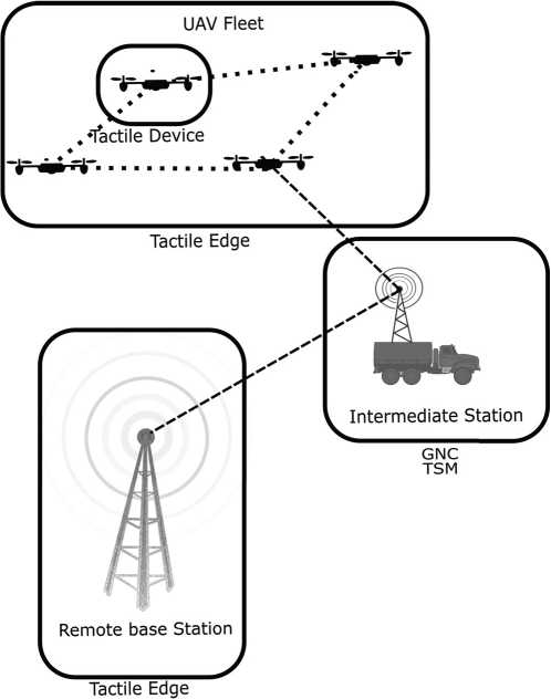
Figure 8.4. Identification of the TI infrastructure in a WNR scenario. The remote base station and the UAVs themselves represent two tactile edges and the GMC and TSM is located inside the intermediate station
The placement and mapping of the support engine is also complex. In WNRs, the selection of a wide set of algorithms, that range from network load balancing to task assignment, can be done distributedly. In this case, differently from the TI standard, each TD contains the SE or a part of it. In the other cases, the SE can be located in the remote station or in the intermediate station.

Figure 8.5. Identification of TI Interfaces in a WNR scenario. Interface Tb is used among the UAVs and Ta is used to connect it, as a tactile edge, to the intermediate station. Interface S is also used as the intermediate station also contains the TSM. Interface A connects the remote base station.
8.4.1.2. Interfaces
If all the robots inside a WNR are TDs, to communicate among each other the interface to be used is the Ta, while interface A is used by selected nodes (the gateways) to communicate with the remote station. In the cases where the intermediate station is deployed, then the robots could communicate with it using a Tb interface. This is different from the standard TI as it is defined that all the TD have an A interface active. The identification of the interfaces S and O is complex. As the SE can be distributed among nodes, being placed in the intermediate station or even in the remote station, the interfaces S and O could be merged with the Ta or even Tb or A.
8.4.1.3. Bootstrapping
The literature (Holland et al. 2019) defines a set of protocols to bootstrap the system. These protocols have been designed with the aim of providing different solutions to TI bootstrapping in case of different scenarios. The protocols describe the steps for the device and interfaces to follow in order to activate the Tactile Internet in a scenario. Some of them are unsuitable for WNR operations as these include phases where the system is in a dormant state (the robots are inside the intermediate station, moving towards the area of interest of the example scenario) and long-range wireless links that could be subject to disruption. Furthermore, the WNR is managed, either in a distributed or centralized way, as a whole. The robot operation parameters as defined in advance refer to a machine-to-machine scenario and are often synchronized.
These peculiarities reduce the choice of possible bootstrapping protocols to the ad hoc TI paradigm, that assumes no infrastructure is a priori online and that the communication is initiated by the tactile edge. In reference to the example, it is supposed that the intermediate station arrives in the designated area and then launches the UAVs. While the UAVs fly into their initial position, the tactile devices are activated and connected via the Tb interfaces. Once the tactile edge is formed, it starts the bootstrapping by requesting to communicate with the intermediate station and then the remote station. The delays and periodic handshakes accounted for in Holland et al. (2019) do represent a small resource delta with respect to the necessary control traffic.
8.4.1.4. KPI mapping
According to the section content, it is now possible to define the features of the TI interfaces involved according to the needs of the WNR scenario. It is provisioned that Ta interfaces will always have to support the kinesthetic/GPS data among the UAVs, as well as the low-frequency sensor data. Thus, these interfaces will have to support the KPIs of Table 8.1. They will also have to support the low-frequency aggregates. The interface Ta will need to support aggregates of Tb and the extra data the Gateway UAVs collect from the swarm, similar to the low-frequency video features of the same table. There would also be events when the high-frequency sensors would be activated on selected UAVs. As per-scenario, it would be necessary to aggregate or create new interfaces in order to transmit increased bandwidth data up to the intermediate station. Multiple Ta interfaces from multiple UAVs could be arranged to split and transmit the high-frequency data and multiple gateways could connect to the intermediate station at the same time. In any case, the A interface should be capable of supporting multiple high-frequency streams as shown in Figure 8.6.
8.5. Conclusion
In this chapter, we have started from the definition of Wireless WNRs, introduced some important examples and then defined the expected traffic inside and through it. This was done to verify whether it is possible to encase the WNR paradigm into the TI and provide a guideline for researchers and implementers that wish to continue to create and develop wireless networked robotics. We have demonstrated that it is possible to translate WNR traffic features into the KPIs of TI and then use them to map the WNRs inside it. We have identified a new use case for TI to include WNRs, how to map the components of WNRs into the TI framework and what interfaces and bootstrapping protocols to use. We hope that this groundwork could also be used to continue the work on the WNR Technical Committee and its standard.

Figure 8.6. A WNR uses aggregate Ta TI interfaces to support high-frequency sensors
8.6. References
Boss, G.J., Hamilton, I.R.A., Mukherjee, M., Mukherjee, M. (2016). Deployment criteria for unmanned aerial vehicles to improve cellular phone communications. US Patent 9,363,008.
Campolo, C., Molinaro, A., Iera, A., Menichella, F. (2017). 5G network slicing for vehicle-to-everything services. IEEE Wireless Communications, 24(6), 38–45.
Cao, H., Gangakhedkar, S., Ali, A.R., Gharba, M., Eichinger, J. (2016). A 5G V2X testbed for cooperative automated driving. 2016 IEEE Vehicular Networking Conference (VNC), IEEE, pp. 1–4.
Culbertson, H., Unwin, J., Kuchenbecker, K.J. (2014). Modeling and rendering realistic textures from unconstrained tool–surface interactions. IEEE Transactions on Haptics, 7(3), 381–393.
Fotouhi, A., Qiang, H., Ding, M., Hassan, M., Giordano, L.G., Garcia-Rodriguez, A., Yuan, J. (2019). Survey on UAV cellular communications: Practical aspects, standardization advancements, regulation, and security challenges. IEEE Communications Surveys & Tutorials, 21(4), 3417–3442.
Holland, O., Steinbach, E., Prasad, R.V., Liu, Q., Dawy, Z., Aijaz, A., Pappas, N., Chandra, K., Rao, V.S., Oteafy, S., Eid, M., Luden, M., Bhardwaj, A., Liu, X., Sachs, J., Araújo, J. (2019). The IEEE 1918.1 “tactile internet” standards working group and its standards. Proceedings of the IEEE, 107(2), 256–279.
Isler, V., Sadler, B., Preuchil, L., Nishio, S. (2015). Networked robots [TC spotlight]. IEEE Robotics Automation Magazine, 22(3), 25–29.
Jalali, A. (2018). Broadband access to mobile platforms using drone/UAV background. US Patent 9,859,972.
Kansal, A., Rahimi, M., Estrin, D., Kaiser, W.J., Pottie, G.J., Srivastava, M.B. (2004). Controlled mobility for sustainable wireless sensor networks. 2004 First Annual IEEE Communications Society Conference on Sensor and Ad Hoc Communications and Networks, 2004. IEEE SECON 2004. IEEE, pp. 1–6.
Manfredi, S., Natalizio, E., Pascariello, C., Zema, N.R. (2020). Stability and convergence of a message-loss-tolerant rendez-vous algorithm for wireless networked robot systems. IEEE Transactions on Control of Network Systems, 7(3), 1103–1114.
Marshall, A., Yap, K.M., Yu, W. (2008). Providing QoS for networked peers in distributed haptic virtual environments. Advances in Multimedia, Article ID 841590.
Matheus, K. and Königseder, T. (2017). Automotive Ethernet. Cambridge University Press, Cambridge, UK.
Muzaffar, R., Yanmaz, E., Raffelsberger, C., Bettstetter, C., Cavallaro, A. (2020). Live multicast video streaming from drones: An experimental study. Autonomous Robots, 44(1), 75–91.
Natalizio, E. and Loscrí, V. (2013). Controlled mobility in mobile sensor networks: Advantages, issues and challenges. Telecommunication Systems, 52(4), 2411–2418.
Natalizio, E., Zema, N.R., Yanmaz, E., Pugliese, L.D.P., Guerriero, F. (2019). Take the field from your smartphone: Leveraging UAVs for event filming. IEEE Transactions on Mobile Computing, 19(8), 1971–1983.
Steinbach, E., Strese, M., Eid, M., Liu, X., Bhardwaj, A., Liu, Q., Al-Ja’afreh, M., Mahmoodi, T., Hassen, R., El Saddik, A., Holland, O. (2018). Haptic codecs for the Tactile Internet. Proceedings of the IEEE, 107(2), 447–470.
Zema, N.R., Natalizio, E., Ruggeri, G., Poss, M., Molinaro, A. (2016). Medrone: On the use of a medical drone to heal a sensor network infected by a malicious epidemic. Ad Hoc Networks, 50, 115–127.