10 Proposed Applications to Biomedical Photonics
In the present chapter, expected applications of molecular layer deposition (MLD) to biomedical photonics are proposed. Although most of the proposals have little experimental confirmation, they will hopely provide some insights in the fields of biomedical research.
10.1 Therapy for Cancer Utilizing Liquid-Phase MLD
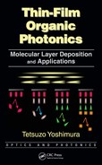
Liquid-phase MLD [1, 2, 3 and 4] is expected to be a powerful process in cancer therapy. Figure 10.1 shows a liquid-phase MLD process for stacking different kinds of functional molecules with designated arrangements on cancer cells [1]. The human body is the chamber and the cancer cells are the substrates for MLD in this case. In step 1, molecule A is introduced into a human body. Molecule A selectively adsorbs on cancer cells. In step 2, molecule B is introduced into the human body and is stacked on molecule A. In a similar manner, molecules C and D are introduced successively, and molecular wires having an A/B/C/D structure can be built on cancer cells. Such a tailored structure will be applied in cancer therapy.
10.1.1 PHOTODYNAMIC THERAPY USING TWO-PHOTON ABSORPTION WITH DIFFERENT WAVELENGTHS
An example of expected applications of liquid-phase MLD is photodynamic therapy (PDT) for cancer shown in Figure 10.2 [1]. In PDT, photosensitizers like Talaporfin sodium [5] are selectively adsorbed on cancer cells. The photosensitizers are then exposed to a light beam. When the photosensitizers are excited, by absorbing the light, they generate singlet oxygen, which damages the cancer cells.
In conventional PDT, a molecule is used as the photosensitizer. By using the tailored molecular wire fabricated by MLD for the photosensitizer, variations of the therapy will expand. As an example, we propose PDT utilizing the four-level two-photon absorption. Figure 10.3 shows this concept [1]. In the four-level two-photon absorption [6], as shown in Figure 10.3(a), a photon with a wavelength of λ1 excites an electron from the S0 state to the Sn state in a molecule. The excited electron in the Sn state transfers to the T0 state. Then, a photon with another wavelength of λ2 further excites the electron to the Tn state to induce a chemical reaction. This mechanism enables us to widen the region where PDT is effective as mentioned below.
In conventional PDT, the excitation light cannot reach the deep part of the region containing cancer cells. By using two-photon absorption with different wavelengths, a three-dimensional attack on cancer cells will be possible as shown in Figure 10.3(b). In the four-level two-photon absorption, the chemical reaction occurs only in regions, where photons with λ1 and photons with λ2 coexist; therefore, the chemical reaction can be selectively induced in specific regions by controlling the direction of the light beam.
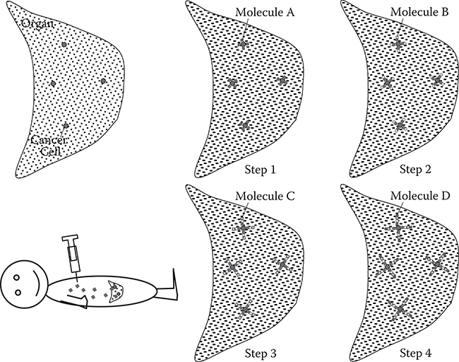
FIGURE 10.1 A liquid-phase MLD process for stacking functional molecules with designated arrangements on cancer cells.
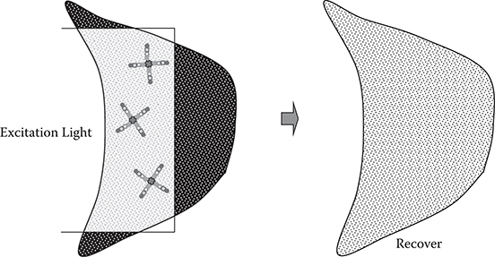
FIGURE 10.2 Schematic illustration of photodynamic therapy.
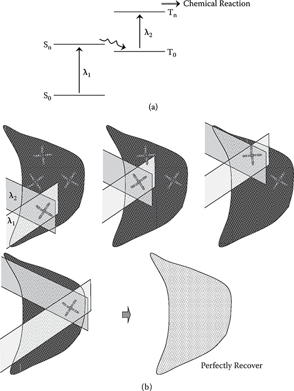
FIGURE 10.3 Concept of photodynamic therapy utilizing two-photon absorption. (a) Mechanism of two-photon absorption, and (b) three-dimensional attack on cancer cells using two light beams with different wavelengths.
Liquid-phase MLD is suitable for constructing the photosensitizers for two-photon absorption. For example, in step 1, molecule A, selectively adsorbs on the cancer cells, is introduced into a body by injection. In step 2, molecule B, with two-photon absorption, is introduced. Molecule B is then stacked on molecule A.
When Molecule A is porphyrin, which selectively adsorbs on cancer cells, and Molecule B is β-carotene, which is connected to the porphyrin on the cancer cells, by exposing the molecules to light of λ1~500 nm and light of λ2, an electron in a β-carotene molecule will be excited to S1 state, then transferred to T1 state by the intersystem crossing, and finally be excited from the T1 state to Tn state, generating a singlet oxygen molecule by the energy transfer from the β-carotene molecule.
The wavelength of ~500 nm for λ1 is too short for actual operation because hemoglobin in blood has strong absorption in the wavelength region. To resolve the problem, donor/acceptor group substitution into the β-carotene molecule, which moves the absorption spectra toward the longer wavelength side as mentioned in Section 5.7, might be effective.
For the selective connection of β-carotene to porphyrin, π-π interaction might be used since both β-carotene and porphyrin have widely-spread π electrons. Another way for the selective connection would be performed by chemical reactions described in Subsection 3.1.1. When –CHO group and –NH2 group are respectively substituted into β-carotene and porphyrin, MLD can be performed by the reaction between –CHO and –NH2 shown in Figure 3.12.
Protoporphyrin, tetraphenylporfin, biacetyl, comphorquinone, and benzyl, etc., for example, are known as molecules with the four-level two-photon-absorption characteristics. In order to apply to the human body applications, the molecules should be selected that are solved in water and exhibit the two-photon absorption with λ1 and λ2 in a range of 600–1000 nm, where light absorption due to hemoglobin is weak.
10.1.2 IN-SITU SYNTHESIS OF A DRUG WITHIN HUMAN BODIES
Finally, another example of expected applications of liquid-phase MLD is proposed. As Figure 10.1 shows, liquid-phase MLD can construct molecular structures by stacking molecules with designated sequencies. This can be regarded as a kind of in-situ syntheses within human bodies [1].
When a molecule of a drug is too large to deliver to target sites in a human body, the drug delivery might become possible by synthesizing the drug from small molecules at the target sites, where the drug is required, by liquid-phase MLD within the human body as follows. First, small molecules A, B, C, and D are prepared. Molecule A is used for selective adsorption onto a target site, for example, cancer cells. Namely, molecule A plays a roll of an anchor for initiation of the drug synthesis at the target site. Molecules B, C, and D are parts of the large molecule of the drug and are used for the synthesis of the large molecule. By injecting molecule A into a human body, it is selectively adsorbed at the target site. Next, molecule B is injected to be attached to molecule A selectivey. By an injection of molecule C, it reacts with molecule A and/or B. Finally, by an injection of molecules D, it reacts with molecule A, B and/or C to complete the construction of the large molecule of the drug. This may widen the range of drug choices.
When a molecule of a drug is poison for some parts in human bodies, a drug delivery with less poison conditions might become possible by synthesizing the drug from non-poison small molecules at target sites by liquid-phase MLD within human bodies in similar ways as mentioned above.
10.2 Indicator for Reflective or Emissive Targets Utilizing R-Solnet
Figure 10.4 shows the indicator concept for reflective or emissive materials using R-SOLNET [8]. The PRI materials are placed between an optical waveguide and microfluidic circuits (MFCs). From the optical waveguide, a write beam is introduced into the PRI material. If materials 1 and 3 are reflective or emissive, the write beam and the reflected or emitted beams are superposed to increase the refractive index in the beam-overlapped regions because the refractive index of the PRI material increases with beam intensity. This effect induces self-focusing to create a SOLNET, that is, a self-organized path between the optical waveguide and MFCs 1 and 3, enabling us to indicate the locations of the reflective or emissive materials as well as to guide the write beam, the reflected beams, and the emitted beams.
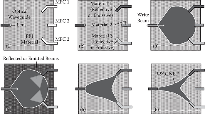
FIGURE 10.4 Indicator concept for reflective or emissive materials using R-SOLNET. From T. Yoshimura, “Proposed applications of 3-D optical interconnect technologies to integrated chemical systems,” Digest of the LEOS Summer Topical Meetings (Bio-Inspired Sensors and Application/Imprinting on Photonic Integrated Circuits), Portland, Oregon, 129–130 (2007).
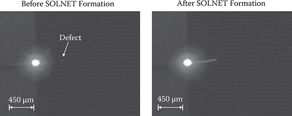
FIGURE 10.5 Indicator for defects and dusts utilizing R-SOLNET.
Figure 10.5 shows an example of the indicator for defects and dusts [9]. In this case, a defect is the reflective material in a PRI sol-gel thin film described in Section 7.3. A write beam with 0.5 mW of power and a wavelength of 405 nm was introduced into the PRI sol-gel thin film for 30 sec under heating at 200°C. It was found that SOLNET is drawn to a defect in the PRI sol-gel thin film, indicating the locations of the defect and, at the same time, guiding the write beam to the defect.
It should be noted that indicator mechanisms may be able to provide methods to find particular targets like cancer cells with emissive cap molecules within the human body and thus guide laser beams to the target. The proposed process is shown in Figure 10.6 [1]. First, emissive cap molecules are attached to cancer cells by MLD in the body. After inserting optical fibers and injecting PRI materials into a region close to the cancer cells, a write beam is introduced from the optical fiber. An R-SOLNET is then constructed to connect the optical fiber and the cancer cells. By introducing surgical laser beams into the SOLNET, cancer cells are destroyed. It may be possible to monitor, in situ, the degree of cancer cell destruction by detecting the backward luminescence emitted from the emissive cap molecules.
10.3 Integrated Photoluminescence Analysis Chips
In integrated photoluminescence (PL) analysis chips [8], MFCs that contain emissive materials are inserted between two optical waveguide films, as shown in Figure 10.7. When excitation light beams with λex in wavelength of a laser diode (LD) are introduced into MFC n from the upper optical waveguide, PL is generated. The PL is collected by the lower optical waveguide, and is guided to photodetector (PD) passing through wavelength filter m, which transmits light beams of λm. By using arrayed MFCs where different materials are injected, PL intensity measurements at λm can be done for the different materials at one time. The same operation can be performed by placing the wavelength filters in series to demultiplex the PL efficiently.
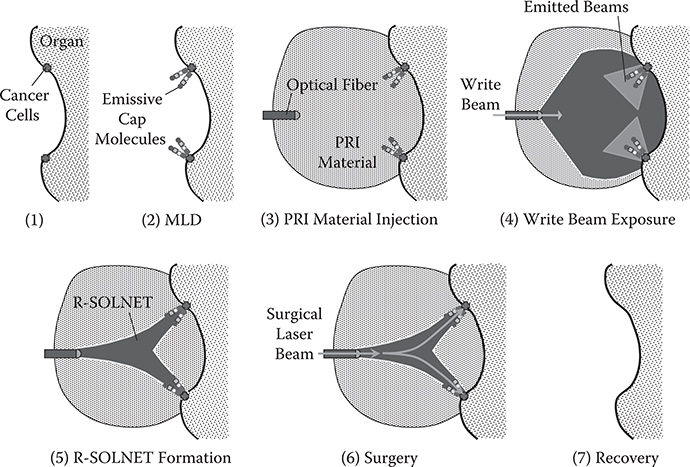
FIGURE 10.6 Possible example of cancer surgery to find cancer cells and guide laser beams to them by MLD and R-SOLNET.
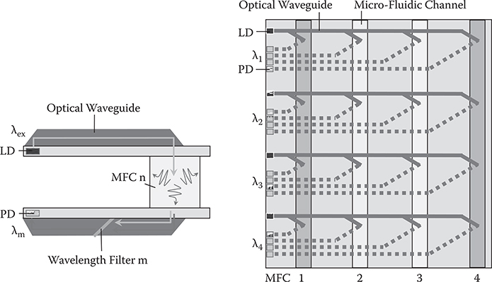
FIGURE 10.7 Integrated photoluminescence analysis chip with 3-D optical circuits. From T. Yoshimura, “Proposed applications of 3-D optical interconnect technologies to integrated chemical systems,” Digest of the LEOS Summer Topical Meetings (Bio-Inspired Sensors and Application/Imprinting on Photonic Integrated Circuits), 129–130 (2007).
By setting an array of optical circuits with embedded wavelength filters for different wavelengths, spectral analysis of PL can be performed for many kinds of materials at one time.
10.4 Molecular Recognition Chip
Molecular recognition chips consist of molecule-sensitive waveguides (MSWs), as shown in Figure 10.8 [8]. The MSW is, for example, a waveguide ring resonator with receptors for particular molecules. When wavelengths of light beams in an input waveguide are scanned, optical power transmitted to the PD at the edge of the output waveguide exhibits a peak at the resonant wavelength of the MSW. When molecules are adsorbed on the MSW, the refractive index of the MSW changes, which induces shifts of resonant wavelengths. For example, when molecule 1, molecule 3, and molecule 4 are contained in the atmosphere, resonant frequencies of MSW 1, MSW 3, and MSW 4 shift. Thus, constituent molecules can be recognized at one time.
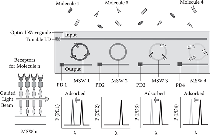
FIGURE 10.8 Molecular recognition chip with the molecule-sensitive waveguide (MSW). From T. Yoshimura, “Proposed applications of 3-D optical interconnect technologies to integrated chemical systems,” Digest of the LEOS Summer Topical Meetings (Bio-Inspired Sensors and Application/Imprinting on Photonic Integrated Circuits), 129–130 (2007).
The MSW can also operate as a device to measure absorption spectra of the adsorbed molecules by introducing white light and analyzing the transmitted light by using a spectrometer.
References
1. T. Yoshimura, “Molecular layer deposition and applications to solar cells and the cancer photodynamic therapy,” Japanese Patent, Tokugan 2010-206098 (2010) [in Japanese].
2. T. Yoshimura, “Liquid phase deposition,” Japanese Patent, Tokukai Hei 3-60487 (1991) [in Japanese].
3. T. Yoshimura, Growth methods of polymer wires and thin films, Japanese Patent Tokukai 2008-216947 (2008) [in Japanese].
4. T. Yoshimura, Integrated photonic/electronic/chemical systems, solar energy conversion systems, light collectors, and optical waveguides, Japanese Patent Tokukai 2009-4717 (2009) [in Japanese].
5. J. Akimoto and K. Aizawa, “Intraoperative photodynamic diagnosis and therapy for malignant glioma using novel photosensitizer Talaporfin,” in Meeting Digest of IPDA 10–18, May 28, 2010, IEICE.
6. C. Brauchle, U. P. Wild, D. M. Burland, G. C. Bjorkund, and D. C. Alvares, “ Two-photon holographic recording with continuous-wave lasers in the 750–1100-nm range,” Opt. Lett. 7, 177–179 (1982).
7. V. D. McGinniss and R. E. Schwerzel, Photopolymerizable composition containing a photosensitive donor and photoinitiating acceptor, U.S. Patent 4,571,377 (1986).
8. T. Yoshimura, “Proposed applications of 3-D optical interconnect technologies to integrated chemical systems,” Digest of the LEOS Summer Topical Meetings (Bio-Inspired Sensors and Application/Imprinting on Photonic Integrated Circuits), Portland, Oregon, 129–130 (2007).
9. S. Ono, T. Yoshimura, T. Sato, and J. Oshima, “Fabrication of self-organized optical waveguides in photo-induced refractive index variation sol-gel materials with large index contrast,” J. Lightwave Technol. 27, 5308–5313 (2009).