
Chapter 1. Classic Campus Network Deployments
If you look at current campus networks from a design perspective, not much has changed in the past fifteen years of networking. Speeds have of course been increased, and fullduplex is now the default, but almost all campus networks are still about Spanning Tree Protocol (STP), assigning VLANs to ports, and providing connectivity to applications, regardless of whether these applications reside in internal datacenters or in the cloud. Spanning Tree Protocol and VLANs were introduced very early in the history of campus networks for scalability and redundancy purposes. Security has just added an extra layer of complexity for configuration. Actually, the campus network has become so reliable and available that many end users (and also managers) view the campus network the same way they view running water and power—the network is just there.
Cisco provides a validated design for campus networks on its website inside the design zone (https://www.cisco.com/go/designzone/). These Cisco Validated Designs (CVD) are lab-tested and provide detailed explanations of the used technologies, possible design choices, and reference configurations that work for most campus networks. Although the design (and configuration) is validated, it does not automatically mean that the design will fit all campus networks. There are always corner cases or specific requirements from the organization that will require small (or large) changes to the design and the configuration.
This chapter is not a repetition of the most recent CVD for campus networks but provides an overview of commonly found campus network deployments. The chapter covers the following topologies:
Three-tier campus network topology
Collapsed-core campus network topology
Single-switch campus network topology
Design choices related to campus networks
Campus Design Fundamentals
In general, the campus (area) network is that part of an enterprise network installed in buildings and offices (and more recently also industrial environments). It is used to connect user endpoints, such as computers, laptops, phones, sensors, cameras, and so on to the enterprise network. It’s the first step in connecting users to the enterprise network. The campus network consists of both a wired and a wireless local area network.
A campus network design (or topology) is commonly built using three distinct functional layers, as illustrated in Figure 1-1.

Figure 1-1 Overview of Campus Functional Layers
The access layer is where endpoints, both user-specific as well as generic, connect to the enterprise network. The access layer consists of both wired as well as wireless high-speed network access. Because this is the layer where endpoints connect, security services are a critical part of this layer. These security services are implemented using IEEE 802.1X network access control, port-based access lists, IP-based access lists, and possibly Cisco TrustSec. As different types of endpoints connect to the same infrastructure, VLANs are used to isolate different functional devices, and Quality of Service is used to provide control over the available bandwidth for specific applications or services, such as video or voice conversations.
The second functional layer is known as the distribution layer. This layer provides scalability and resilience as they are used to logically aggregate the uplinks of access switches to one or more distribution switches. Scalability is accomplished via the aggregation of those access switches, while the resilience is accomplished because of the logical separation with multiple distribution switches.
If, for example, an access switch has a failure, this failure is contained at the distribution switch to which that access switch is connected. Other distribution switches (and thus other access switches) will not experience problems because of that broken access switch. The same level of resilience would be difficult to accomplish if that misbehaving switch is connected to multiple distribution switches. It would require a more complex configuration on both distribution switches. This added complexity in configuration can be reduced by using advanced technologies where two physical switches are configured in such a way that they act as one. This can be accomplished using Virtual Switching System (VSS) or StackWise Virtual on Cisco Catalyst switches or virtual PortChannel (vPC) for Cisco Nexus switches.
The core layer is the highest level in the hierarchical network. Its function is primarily to route traffic between the different campus network switches and the organization’s datacenter, Internet, cloud services, and other connected services. The core layer is required to keep the configuration and operation of the campus network manageable as the number of distribution switches increases in the campus network.
If, for example, an enterprise had six distribution switches and no core layer, each of those six switches would require a connection with all other distribution switches, resulting in a total of 15 (5 + 4 + 3 + 2 + 1) uplinks. If a seventh building were introduced, the number of uplinks needing to be managed would be increased by 6, and so on. Figure 1-2 shows the network diagram for a network without a core layer.
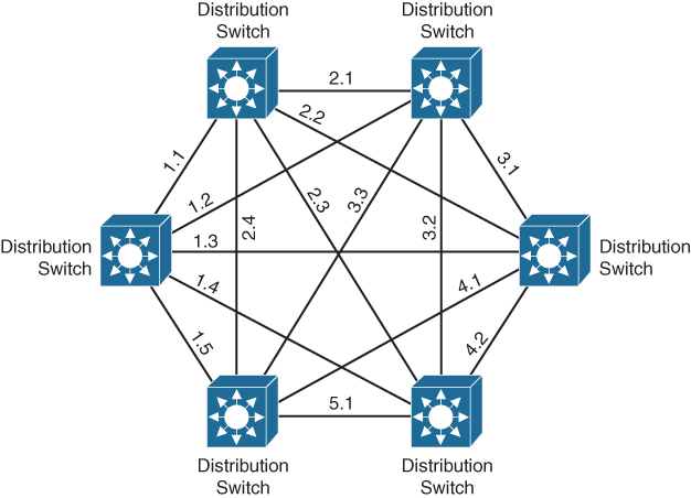
Figure 1-2 Campus Network Without Core Layer
With the introduction of a core layer, where each distribution switch is connected to two core routers (or switches), the network and configuration become much more manageable and scalable, as can be seen in Figure 1-3.
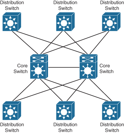
Figure 1-3 Campus Network with a Core Layer
In this setup, each distribution switch has two uplinks, one to each core switch. If an extra distribution switch needs to be added to this network, only two extra links on the core switch are required instead of adding six links, as shown previously in Figure 1-2. In case of a failing distribution switch, only two interfaces on the core switch will see that issue instead of having an issue on all distribution switches. The other distribution switches remain active with no errors or failures.
These three layers combined provide for a campus network topology that is scalable, resilient, and manageable. The topology also allows for adding security, quality of service, and other network services that the enterprise could require.
Three-Tier Design
The most extensive campus network topology is called a three-tier network design. In this design, the three functional layers described in the previous section are all executed by separate switches and other network equipment. Figure 1-4 displays a large campus network based on a three-tier hierarchy.
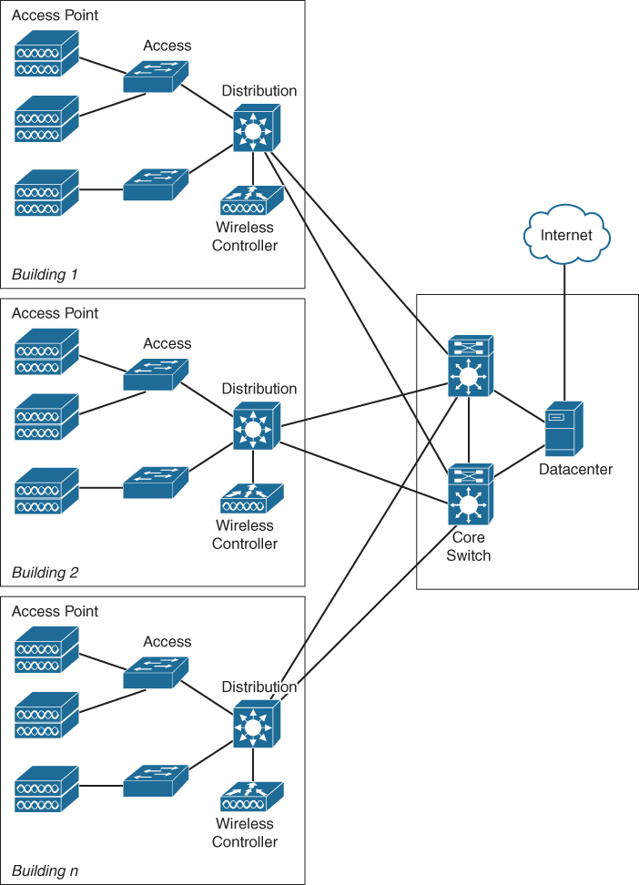
Figure 1-4 Large Campus Network
The three-tier campus network is mostly deployed in environments where multiple offices and buildings are located closely together, allowing for high-speed fiber connections to the headquarters owned by the enterprise. Examples could be the campus network at a university, a hospital with multiple buildings, or a large enterprise with multiple buildings on a privately owned campus.
Two-Tier/Collapsed-Core Design
One of the more modern adoptions of the CVD campus design is a collapsed-core campus network. In this design, the function of the distribution switch and core switch is merged into a single switch. Figure 1-5 displays a collapsed-core campus network design.
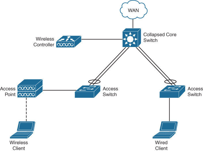
Figure 1-5 Collapsed-Core Network
The key principle behind this design is that there are no loops in the network. Each stack of access switches in a satellite equipment room is connected to the core switch using (usually two) uplinks combined into a single portchannel. The Wireless LAN Controller (WLC) is connected to the core switch, whereas the access points, printers, and workstations are connected to the access switch.
Using local breakout for the wireless network, both wired and wireless clients will share the same functional IP space allocated to this campus network. The different wireless network topologies for campuses are described later in this chapter. It is, of course, possible to have the controller in the datacenter, with its own advantages and disadvantages.
It is common for a collapsed-core network to have the core switch configured in high availability. This is accomplished by having either two switches in a single stack or two core switches in VSS mode. In either design option, the uplinks from the access switches in the satellite equipment rooms are physically separated over the two core switches (that act as one). Even with this high availability, there are physically and logically still no loops in the network. This topology can have the added benefit of removing complexity such as Spanning Tree Protocol.
In general, the access switches act as a Layer 2 switch with a management IP and have all the VLANs defined for the campus network. The core switch provides the Layer 3 functionality for the different VLANs using switch virtual interfaces. The core switch in turn has Layer 3 uplinks to the WAN for connections to the datacenters and the Internet. Depending on requirements, it is possible to use VRF-Lite to logically separate the different IP networks into different VPNs over the WAN to provide isolation of different endpoints.
Collapsed-core campus network designs have become common and typical for a single (large) building.
Single-Switch Design
In smaller environments, such as branch offices or smaller enterprises with fewer endpoints connecting to the network, it is not economically and functionally sound to have separations in the access, distribution, and core layers, so these functions are combined in a single switch. Figure 1-6 displays this network campus design.
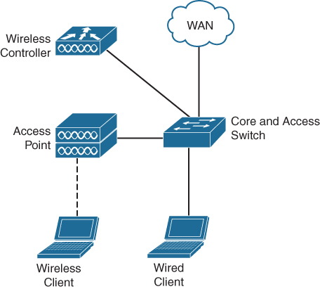
Figure 1-6 Single-Switch Campus Network
As the different functions are merged into a single switch, more complex technologies such as Spanning Tree are not required and can be disabled. This is similar to a collapsedcore network where Storm Control can be used to reduce the impact of broadcast storms on the network. The Layer 3 connections are usually configured on the same switch (most modern access switches support Layer 3 switching with static routing), but in very small networks the Layer 3 connections can also be handled by the router that provides connection to the WAN.
High availability in this type of campus network is, if required, accomplished by creating a stack of two switches, which allows the users to “patch over” the connections to the other switch in case of failure.
The wireless network design itself is dependent on the type of organization. If the campus network is a small branch in a larger enterprise, the access points are configured in FlexConnect, and the controller is located in the central datacenter. If the campus network is a small business or small enterprise, usually a small wireless LAN controller is connected to the access switch to provide wireless controller functionality. The controller functionality could also be cloud-based, depending on the chosen solution.
Wireless Networks
Wireless networks have become common in any enterprise network. In the past decade, the wireless network has changed from a nice-to-have feature (for management) to a mature network infrastructure that more often than not is the primary connecting interface for enterprise endpoints. Wireless networks make use of the shared frequencies in the 2.4Ghz and 5Ghz band. These bands, with distinct specifications within the different IEEE 802.11* standards, make the deployment of a wireless network a complex process that requires specialist knowledge. This section provides a conceptual overview of how Cisco wireless networks operate and which kind of wireless deployments are found in campus networks. Many Cisco-based wireless networks are controller-based wireless networks. In this concept, there is a wireless LAN controller (WLC) and access points.
The WLC is the central point of configuration and management for the complete deployment. The wireless networks, security settings, and configuration of IP interfaces for clients are defined within the configuration of the controller. Also, the operational management of the wireless spectrum is executed by the controller.
The access points (APs) have one or more wireless radios (most commonly two radios, one in 2.4Ghz and one in the 5Ghz band) and handle the communication of the wireless network. Commonly in campus networks, the access points are connected and powered from the wired switch. The access point itself does not have any configuration of its own but receives all information and configuration from the controller.
When an AP boots up, it obtains an IP address and attempts to find a controller. Once it finds the controller, it tries to register with that controller and establish a Control and Provisioning of Wireless Access Points (CAPWAP) tunnel. The CAPWAP tunnel is in essence a transport tunnel for both control traffic between the AP and the controller as well as client traffic.
Once the tunnel is established, the controller sends the proper wireless configuration settings to the AP. The radios are enabled and the wireless networks are broadcasted. In turn, the AP listens for information on the wireless network and shares that information with the controller, so the controller can tune wireless parameters of all the APs in its control to provide as optimal as possible coverage and operation of the wireless network. This latter process of sharing information and managing wireless properties is also known as Radio Resource Management. Figure 1-7 displays a schematic approach of the CAPWAP tunnel and communication flow.
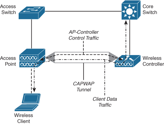
Figure 1-7 Schematic Approach of a Wireless CAPWAP Tunnel and Communication Flow
Once a wireless client wants to connect to the network, it tries to associate itself to a specific wireless network. The AP forwards that request to the controller. The controller in turn handles that association request and executes the authentication process for that client. In this process the AP forwards the messages between controller and client. Once the client is successfully authenticated and associated, a Layer 2 connection exists between the wireless client and the controller. The AP is in essence a bridge between the shared half-duplex wireless network and the controller, forwarding ethernet frames back and forth between the client and the controller. This is shown in Figure 1-7 as the open-arrow dash-dotted line marked as Client data traffic.
Based on this general controller principle, there are four common deployments for a Cisco wireless network:
Central controller with central breakout
Local controller with local breakout
Central controller with FlexConnect
Mobility Express
The following sections describe these deployments in more detail.
Central Controller with Central Breakout
In this deployment, several APs of different campus networks are registered and managed on a central controller inside the datacenter. The client traffic is transported via the CAPWAP tunnel over the WAN toward the central controller, and the wireless client traffic enters the wired network inside the datacenter. Figure 1-8 displays the topology for controller-based central breakout wireless network.

Figure 1-8 Wireless Network Topology Based on Central Controller with Central Breakout
The advantages of this setup are as follows:
Only a single controller needs to be configured and managed for the complete enterprise wireless network.
Traffic is transported from the different campus locations over the WAN toward the central controller so that client traffic can be inspected and optimally routed through to the enterprise applications or the Internet.
There are some disadvantages for this kind of deployment as well:
If the controller has a problem, the problem is essentially replicated across all campus networks. This can have severe impact on being able to get maintenance windows for upgrades, as the complete wireless network is updated all at once.
There is a huge dependency on the WAN. If the WAN is disconnected, the wireless network is down as well.
Also, communication between clients on two different APs always flows through the controller, which adds extra load to the WAN.
Local Controller with Local Breakout
In this specific deployment, the controller is placed within each campus network. CAPWAP traffic remains onsite (within the campus network), and the breakout for wireless clients is from the location of the WLC. Figure 1-9 displays a wireless topology based on local controller with local breakout.
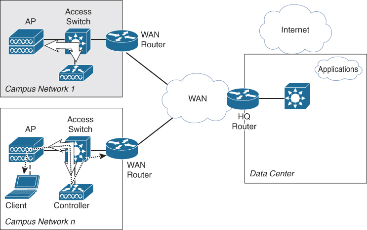
Figure 1-9 Wireless Topology with Local Controller and Local Breakout
One of the key benefits of this deployment is that the wireless network of a campus location is not dependent on the availability of the WAN. Another benefit is manageability and the fault domain. If an onsite controller is broken, only that specific location has wireless issues. The drawback, of course, is that each campus location needs to have its own controller, which not only adds cost but also introduces the requirement of a central tool to manage the configuration of the distributed controllers.
Central Controller with FlexConnect
This deployment option uses a central controller for the configuration and management of the APs; however, the traffic of clients is not sent out via the central controller but locally over the Ethernet interface of the AP. Figure 1-10 displays the topology of a central controller with FlexConnect.
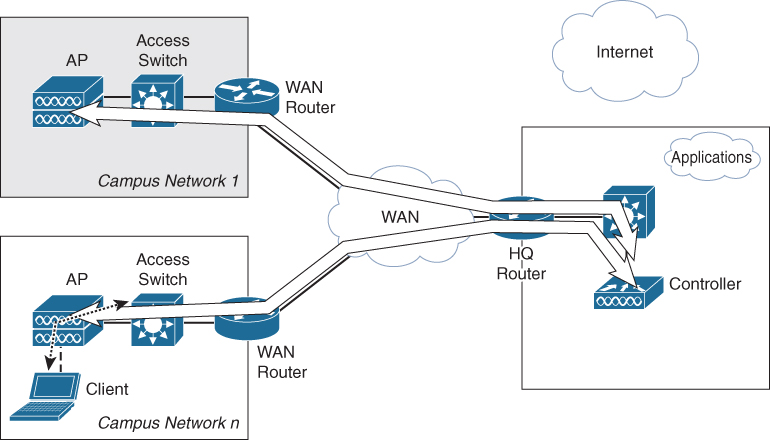
Figure 1-10 Wireless Topology Based on Central Controller with FlexConnect
The primary targets for this kind of deployment are smaller branch locations with up to 100 APs inside the campus network. Although this feature works well, clients roaming between two access points will incur a mac-move from one port on the switch to another. If this happens frequently, the switch will log messages that can be interpreted as an error, while it is normal behavior.
Mobility Express
Instead of using a dedicated local controller for radio resource management and configuration management, it is now also possible to use Mobility Express. Mobility Express is available on 802.11ac Wave2 access points. It allows the AP to become a lightweight controller to provide central configuration, radio resource management, and some other features to APs in the local network. Mobility Express is limited up to 50 APs, depending on the type of 802.11ac Wave2 AP that is used as controller. FlexConnect is used for the breakout of client traffic, and failover is realized (and configured automatically) between all 802.11ac Wave2 access points in the network that can become a new master AP.
Functionally, the AP has controller software running besides the AP functions with a separate IP address and management. Figure 1-11 provides a schematic function of a Mobility Express–enabled access point.

Figure 1-11 Mobility Express Enabled Access Point
Within the AP, the network interface is shared via the operating system (C-OS) to both the IP address of the AP as well as the controller software. Each has its own IP address, and the AP is managed by the IP address of the controller software.
Anchor Controller
On top of these four Cisco wireless network deployment options, there is also a special use case for wireless guest services that involves a second controller, called anchor controller. In this case, the specific wireless guest network is not terminated on the normal controller (which also terminates the AP), but the client traffic is forwarded via a second tunnel to the anchor controller. This anchor controller is often placed in a DMZ, to prevent wireless guest users from accessing the internal network.
Each deployment option for wireless has its own advantages and drawbacks. Which choice is valid depends on several factors, including not only technical but also organizational aspects, such as the size of the organization, number of campus sites, availability of the WAN, and security requirements. Cisco provides several design considerations and technical factors in its Wireless Deployment Guide. Of importance for campus networks is that the wireless network has become the primary connection option for many enterprise networks.
Design Choices
As with any design, several choices or options are available within the framework to adapt the concepts to the specific requirements of an enterprise, whether it is a single switch, collapsed core, or a full three-tier campus network. Two design choices genuinely affect the way the campus network behaves and have an impact on scalability and possibly even an impact on the transformation to Intent-Based Networking.
Handling Redundancy
There is one inherited complexity when it comes to local area networks (LANs). This complexity is redundancy in Layer 2 of a LAN. A Layer 2 network is built upon the assumption that all devices within the same Layer 2 domain are directly reachable from one another (for example, a single broadcast domain). Every device in a single broadcast domain can be reached over a single path. Furthermore, single paths in any network guarantee a single point of failure in case that path has a failure.
As a network engineer you want to remove these single points of failure without introducing too many complex problems. Over the years many concepts and protocols have been designed and implemented to overcome this problem in Layer 2. And thus there are some design choices in a hierarchical campus network design model.
The most common option to realize redundancy in a Layer 2 domain without having a loop in the network is Spanning Tree. It is a protocol that uses the shortest path algorithm from Moore-Dijkstra and a root election. Every Layer 2 network has a single root, and every other switch is connected in the most optimal path to that root switch. Every other alternative path is blocked for traffic by Spanning Tree Protocol. Figure 1-12 displays a campus network with Spanning Tree enabled where single uplinks are blocked.

Figure 1-12 Campus Network with Spanning Tree Blocking Uplinks
There are a few drawbacks to Spanning Tree Protocol in general. One is that if the switch sees an incoming Bridge Protocol Data Unit (BPDU) packet, Spanning Tree Protocol will kick in and no traffic will flow as long as the shortest path algorithm is running. A second problem is that the root election is primarily based on a MAC address and priority. If you do not configure them, it is possible that the distribution switch is not configured as root, but instead an access switch or a non-manageable switch that is accidentally connected by an end user. Troubleshooting Spanning Tree Protocol is a complex task in large environments. And last but not least, every alternative path is blocked by Spanning Tree Protocol, so only half the available bandwidth is used.
Another option to have redundancy is to make the Layer 2 domains smaller and use Layer 3 on the redundant paths. As opposed to Layer 2, IP (as Layer 3 protocol) is designed with the assumption that multiple paths are available for the destination IP address. So if the uplinks between two layers are based on Layer 3, the problem of loops in the Layer 2 network is mitigated. Figure 1-13 provides a campus network with Layer 3–based connections between distribution and access layer.
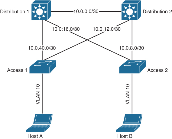
Figure 1-13 Campus Network with Layer 3 Uplinks Between Access and Distribution Switches
Unfortunately, using Layer 3, for example, between the access switch and the distribution switch, means that a host in VLAN10 on access switch A cannot talk to another host in the same VLAN10 on access switch B. Although these two VLANs have the same VLAN identifier, they are logically two separate broadcast domains. Another problem is the introduced complexity of configuring point-to-point IP addresses on the uplinks.
A third option to have redundancy in Layer 2 and using all bandwidth is by introducing technologies so that two physical switches act together as one, whether it is via a stack, Virtual Switching Solution (VSS) on Catalyst switches, or Virtual PortChannel (vPC) on Nexus switches. The access switch thinks it is communicating with a single switch over two interfaces bundled in a Portchannel. The technology is proven and is commonly used in campus networks.
Because there are no loops in this network, it is a valid design to either remove Spanning Tree configuration completely or use a single Spanning Tree instance for all VLANs in the campus network. By using technologies such as storm control, it is possible to prevent broadcast storms and loops. BPDU Guard helps in preventing other switches from introducing Spanning Tree in the campus network. You do have to be careful that the BPDU packets are sent over the default member interface of a portchannel and not over the portchannel itself. So you cannot use Spanning Tree Protocol to detect failures of the portchannel. Figure 1-14 displays a Collapsed-core campus topology with VSS.

Figure 1-14 Campus Topology with VSS in Distribution Layer
Other technologies such as UniDirectional Link Detection (UDLD) can be used for that matter. Removing STP provides the benefit of preserving single path broadcast domains, but introducing VSS can have a (limited) drawback on complexity for operating and troubleshooting the distribution switch. The benefit of not having Spanning Tree often outweighs this disadvantage. In smaller campus networks a stack of Cisco switches can also be used to accomplish similar functional behavior.
In general, all options are used extensively in campus topologies. It is very common nowadays to use VSS or VPC for connecting access switches to the distribution switches. It is a valid design option as long as access switches are not interconnected and loops still exist in access switches. In some environments, such as a campus network for a production facility, VSS or VPC cannot be used because of cabling restrictions (for example, some satellite rooms can be connected only via another satellite equipment room), and Layer 3 can be a good option in such situations. It is up to the network designer to balance out all options in conjunction with the specific requirements and physical constraints of the campus network to create the most optimal campus network design with redundancy.
Cloud-Managed
The cloud is perhaps not immediately thought of as a design choice for campus networks, but actually there are several situations where it does have an effect on your deployment.
With the acquisition of Meraki, Cisco now also has a completely different line of solutions for the design and deployment of campus networks. Meraki networks are based on two key design principles:
Cloud-managed: Every Meraki device, whether switch, access point, or firewall, is managed through a portal in the cloud. The devices might have a limited interface to do the minimal required configuration to get the device connected to the Internet. The rest of the configuration is managed completely through a cloud portal. If you want to create a new wireless network (SSID), it’s done via the cloud portal and pushed to the access points. Creating a new VLAN is done via the portal and again pushed via Internet to the device.
If there is no Internet connection, the switch or access point will continue to work; you just cannot manage the device.
Easy graphical user interface: The other key design principle is ease of use. As with many cloud-managed services, they are commonly easy to use and configure. (It’s part of the business case for cloud-managed services.) A Meraki engineer once said that if a technology or feature cannot be enabled/configured with the flip of a switch in the portal, that feature will not be implemented. Another reason for this key design principle is also that Meraki networks are aimed for small and medium enterprises. These enterprises usually do not have a fully trained network operations staff available but more a general systems operator/manager and external partners that supply extra hands and experience if needed. So configuring a Meraki network (and its devices) needs to be simple and easy.
These design principles are, of course, reflected in their network switches and access points. And although the conceptual structure of a campus network topology (three-tier, collapsed-core, or single-switch) is not dramatically changing, there are some extra design choices that can be made for some (smaller or specific) situations.
Perhaps one of the most visible extra design choices is for wireless networks. With Meraki, it is now possible to use a cloud-based controller instead of having a controller on the campus network. By not having a local controller (for smaller collapsed-core and single-switch enterprise environments), there is a reduction in the number of network devices at a specific site, and by not using a central controller, a possible strain on the WAN (both bandwidth as well as availability) is also reduced. As long as the site has an Internet connection, there is a wireless connection. Another benefit is that the cloud portal provides an easy overview of connected clients and sites, which can make remote troubleshooting easier.
As with any design choice, there are also drawbacks. Specifically in larger enterprises it can become a problem to implement and operate two distinct and different platforms. It is, for example, more difficult to create a single pane of view for all managed network devices and connected endpoints. Also, it could be that, due to the design principles, certain features are either limited or not available with the Meraki products, and there is a requirement for that specific feature. A good example for this situation is a wireless network that needs to be designed and configured in an office or warehouse with some complex spectrum behaviors.
A similar design choice is applicable for the wired part of a campus design. Although functionally the concept of a collapsed core or single switch is not changing, if the specific campus network does not require advanced routing protocols or complex security mechanisms, a cloud-managed campus network can be a valid choice to have the benefits of ease of use and central management without too many complex tools.
Summary
In general, three types of topologies are deployed in campus networks:
A three-tier deployment in which each function of a campus network (access, distribution, and core) is placed in dedicated switches. A three-tier deployment is commonly found and used in enterprises where the campus is comprised of several (large) buildings with a high-speed fiber network (LAN) interconnecting those buildings with the main building that contains the datacenter. Inside each building access switches connect to the distribution switch, which in turn is connected via the highspeed LAN between the buildings to the core switch. Quite often in this kind of deployment the connection between the core and distribution is based on Layer 3, so that VLANs are isolated within a building.
Within a collapsed-core deployment the distribution and core function are merged into a single logical core switch. Access switches still connect to the distribution switch, and the distribution switch is connected to a WAN/MAN for connectivity to the datacenter. This kind of deployment is commonly used in environments where there is either a single building or buildings are connected to the datacenter via external WAN providers.
The last deployment topology commonly found is a single-switch deployment, where all three functions are merged into a single switch. This is the simplest campus network deployment and is commonly found in branch offices and smaller enterprises.
On top of the wired deployment topology, a wireless network is being deployed. Over the past decade, wireless networks have transitioned from “nice-to-have” to the primary connection method for enterprise endpoints. Most wireless deployments found inside campus networks are controller based, where the access points communicate with a controller. The controller centrally manages both the wireless configuration and the security settings as well as radio resource management and client authentication.
Although wireless has become increasingly more important and the speeds inside the campus have increased over time, the designs and technologies used in campus networks have not changed much. VLANs are still used to logically separate endpoints into different logical fault domains, and the Spanning Tree Protocol is intensively used to prevent loops in the network. Campus networks have become so available, reliable, and trustworthy that many users see the campus network similar to power and running water—it is always there and it just works.