
Chapter 8. Phase Two: Prepare for Intent
Chapter 7, “Phase One: Identifying Challenges,” described how phase one is used to identify and organize challenges for a successful transformation to Intent-Based Networking (IBN). This chapter describes phase two of the transformation.
It is assumed that phase one has been completed successfully and management has signed off on the action plan from the first phase. This approval is important for this phase because new technologies or tools can be introduced, and some common workflows might need to change as well. It is also assumed that the operations team is deeply involved in all tasks in phase two. This is critical for the acceptance of new workflows or tools within the operations team and to enable change.
The main focuses of this phase are to meet all requirements, solve identified challenges from phase one, and prepare the network (including the network operations team) for the transformation to IBN.
Phase two accomplishes these focuses by executing the following steps, which are covered in detail in this chapter:
It is not necessary to execute these tasks sequentially, although some tasks might have preference or priority over another. Elaboration to why a task might have preference over another will be explained at the specific task.
Matching Requirements
One of the most important steps in this phase is making sure that not only the network infrastructure but also the organization matches the requirements for an intent-enabled campus network. As described in Part I, “Overview of Intent-Based Networking,” IBN is a perspective on Cisco DNA. It describes how the network should be designed and operated to face the changes that will happen (or are already happening). IBN assumes with this perspective a number of requirements to be met. This task is used to make sure all requirements for IBN as well as the transformation to IBN are met. These are grouped around the organization (process) and networking (hardware and software).
This step is probably the most complex within this phase as it can take a long time for changes to settle in. Although it is possible to perform the next task in parallel, it is strongly recommended to keep the primary focus on this task as it also enables a smoother implementation of subsequent tasks.
Organizational Requirements
Although it might sound strange at first, matching the organizational requirements is one of the most important tasks within this phase. An Intent-Based Network is much more about how to operate and manage the campus network than the technologies. Also, based on the output of the first phase, hardware and software might need to be replaced to be able to run an Intent-Based Network, which can take multiple years to accomplish within a large enterprise. The transition to an Intent-Based Network can be compared with the transition to the cloud in the past. Enterprises had to be ready for that transition too. The following requirements should be met within this phase to enable a successful transformation to an intent-based network.
Maturity Level of an Organization
Chapter 7 described the concept for the maturity level of an organization. For any transformation to be successful, the organization needs to have a certain level of maturity. If not, there is a high risk that a transformation will start with a lot of optimism and energy, but as soon as pressure occurs for the transformation, often the enterprise and/or staff fall back into the old ways and the transformation fails. Part III, “Organizational Aspects,” provides more details on this behavior. If an enterprise has at least a level 3 (and preferably on some items a level 4) on the maturity levels, this risk is reduced because there is a described vision, including a strategy and commitment to achieve that described vision.
The way an Intent-Based Network operates also requires a high level of standardization for both configuration and procedures to be successful. (Each Intent is essentially a small piece of configuration that can repetitively be deployed on the network.) Inherently, IBN requires that same level of maturity of the enterprise for a successful transformation.
Therefore, one of the most critical and important tasks in this phase is to make sure that the enterprise at least has a maturity level of three and preferably four on certain aspects. Phase One determines the current level of maturity. Table 8-1 describes which maturity level must minimally be reached within this task.
Table 8-1 Overview of Maturity Levels to Achieve Within the Enterprise
Aspect |
Maturity Level |
Remarks |
Incident management |
3 |
Written procedures for incident management provide the benefit of consistent workflow through incidents. |
Change procedures |
3 |
Change procedures within the network must be written down to increase the chance of a successful implementation of IBN. |
Disaster recovery and risk management |
3 |
Disaster recovery and risk management are often overseen as the network is usually very reliable. However, having a level 3 on this aspect provides the benefit that the business understands the risks and impact of a major failure in the network. (It also helps the business understand that networking is not a cost center but a business enabler.) |
Lifecycle management |
3 |
Lifecycle management describes at which point in time the hardware and/or software needs to be replaced within an organization. If this aspect is at level 3, processes are in place to initiate hardware and software replacements before a failure occurs or the support on the equipment has ended. A written and documented lifecycle management process proactively supports running modern and supported network equipment that is ready for adopting new technologies. |
Design and configuration |
3 |
Regardless of whether designs, configurations, and software images are standardized, documentation must exist for the IT environment to be able to standardize them. |
Vendor and product selection |
4 |
The transition to an Intent-Based Network takes a long time. It is important to have a written vendor strategy including a consistent product selection that focuses on the future usage as well as hardware replacement. |
Generic IT vision and strategy |
4 |
IBN might require new hardware to be procured. Having a generic IT vision and strategy for the upcoming five years will benefit both in procuring new hardware as well as keeping commitment from management during the transformation. |
Implementing (and supporting) change inside an organization commonly takes a much longer period of time than the technical implementation that enables that change. For example and from personal experience, technically connecting an enterprise to a trusted supplier to automatically send purchase orders and receive invoices electronically might only take two months. (The actual link takes even less time.) But it will probably take the staff of the individual departments of each organization at least a year to get accustomed to that automated behavior and that faxing/mailing or phoning an order is no longer required.
This example is common for any change, and a parallel can be made in achieving higher maturity levels within an organization. Changes take time both in writing down visions, strategies, and procedures and in allowing staff to get accustomed to them. The end result will be that the quality of the organization as a whole will improve as well.
It is, of course, not required to overspecify all aspects in tightly written procedures where the procedures have become leading over the processes. Keep the written procedures pragmatic and manageable; procedures must always be supportive of the processes and not vice versa. A pragmatic approach to the procedures will not only keep the organization lean and flexible, but make it much easier for the employees to follow those procedures and therefore adopt the change more rapidly.
Resource Availability
Traditionally, projects are set up to implement changes for an organization, whether this is the upgrade to a new mail system or replacing network equipment at a specific branch location. In most cases, project managers are given a limited budget (often too little), a critical deadline, and a number of external resources. Sometimes the project manager has an incentive to deliver the project on time (via a bonus or an even bigger project).
What happens is that after the project is finished, the project is signed off with possible shortcuts and open items, and the operations team is faced with these open items. The operations team is given yet another new tool to manage a small piece of the network, and they have to deal with it on a day-to-day basis, while the project team is disbanded and the project manager has moved onto the next project.
A Cisco DNA is designed not only for the digital business to succeed, it also defines a design for a network infrastructure that is easy to understand and resilient for changes and specializations, while remaining as standardized as possible. Intent-Based Networking (IBN) is a perspective to that architecture; it describes how you can operate and manage a Cisco DNA. IBN is essentially written and targeted for the network operations team so that they can cope with the challenges and changes they are facing or will face in the near future.
IBN is also about changing the operation itself, leveraging the power of tools to do repetitive work consistently and predictively and to be easily scalable. The operations team needs to manage and operate those tools on a day-to-day basis, as well as they need to undergo changes. Their jobs will not be lost, but their tasks and responsibilities will change over time.
Conclusively, it is a requirement that all tasks related to the preparation and implementation of an Intent-Based Network need to be executed in a close relationship with the network operations team, or preferably by the network operations team itself.
Unfortunately, the operations team is often already overloaded with delayed work and responding to incidents. If a person has too much on his or her plate, that person only has focus for the work that needs to be done. The person often literally does not have time to consider changing certain aspects of the work at all.
Ideally, all phases are to be performed by the operations team so that the team can take ownership of the transformation. The operations team needs to see that the required changes are beneficial to the team.
Therefore, it is an important requirement to get commitment from management to make resources within the network operations team available for the different tasks related to the transformation to an Intent-Based Network. One of the possibilities to achieve this within the network operations team is to add extra (external) staff to the operations team so that the workload is shared among more staff, which results in increased availability within the network operations team. That allows the network operations team to perform the tasks necessary for transformation themselves.
Alternatively, the operations team supports an external project team for the transformation, where the operations team has a (semi-) final say in specific choices as long as these decisions benefit the ultimate goal of implementing Intent-Based Networking.
In conclusion, two organizational requirements must be met within this task:
The organization needs to operate at a certain maturity level that encompasses written and documented visions, strategies, and procedures. It is clear that the organization also adheres to and follows the vision and procedures in the day-to-day operation. Changing an operation to that level of maturity can take some time as it demands commitment from management and behavioral change from staff. While an increase in maturity will bring documentation in the form of designs and procedures, these documents must never become leading; rather, a pragmatic approach should be taken so that the steps toward the desired maturity level are small.
Instead of having external project teams execute changes isolated from the network operations team, the network operations team is deeply involved, preferably fully enabled, to execute the different projects and tasks to transform to Intent-Based Networking.
Network Infrastructure Requirements
Another aspect of the task to match requirements is to meet the requirements on hardware and software for an Intent-Based Network, because IBN is based on Cisco DNA. Cisco DNA sets forth a number of requirements in both hardware and software for the network infrastructure devices. For example, not all network devices can run virtual network functions or support virtual routing and forwarding (VRF) to isolate logical networks on the IP layer. The task continues on the inventory of hard- and software that was made in phase one and mandates that all network equipment used for IBN meets the requirements.
Phase one produced two tables related to the inventory task executed. Table 8-2 and Table 8-3 are a copy from the example provided in phase one.
Table 8-2 Overview of Installed Hardware and Software
Device Family |
Device Type |
Device Name |
SW Version |
Update SW Required? |
Install Date |
Replacement Required? |
Replacement Moment |
Routers |
C2951 |
C1-RT01 |
15.2 |
No |
Jan 2016 |
Yes |
Jan 2021 |
Switches |
WS-C3650-24PS-S |
C1-AS01 |
3.7 |
Yes |
Mar 2017 |
No |
|
Switches |
WS-C6509-E |
C1-DS01 |
12.2 |
N/A |
Oct 2014 |
Yes |
ASAP |
Wireless |
AIR-CT5508 |
C1-WS01 |
8.5 |
N/A |
Jan 2017 |
Yes |
ASAP |
… |
|
|
|
|
|
|
|
Table 8-3 Aggregated Overview of Campus Network Hardware
Device Family |
Device Type |
Total Switches |
IBN Ready |
Remarks |
Switches |
WS-C3650-24PS-S |
40 |
Conditional |
Max 3 VNs* |
Routers |
C2951 |
2 |
No |
|
Switches |
WS-C6509-E |
3 |
No |
End of life |
Wireless |
AIR-CAP2602I |
200 |
No |
End of life |
Wireless |
AIR-CT5508 |
2 |
No |
End of life |
… |
|
|
|
|
*IP Base of the Catalyst 3650/380 provides maximal 3 virtual networks (or VRFs); switches running IP Services (ending with E in the SKU) can have maximal 64 virtual switches. |
||||
The specific actions related to this task are dependent on the contents of these two tables. If all hardware is IBN ready, but not running the appropriate software, then a plan should be written and executed to upgrade the devices to a software version supported for IBN. For example, IOS-XE version 16.6 or higher is required for Model-Driven Telemetry. This plan should be written and executed in close cooperation with the operations team.
However, it is quite realistic to state that besides software upgrades, the hardware, for example, switches or wireless controllers (or even access points), needs to be replaced as well. In that case, the upgrade plan needs to be combined with an investment plan.
The investment plan needs to be written in a clear and concise manner where several priorities should be organized and matched against the available budget, available resources, state of equipment (install date, end of life), and impact. As an example, replacing a Cisco Wireless Lan Controller (WLC) 5508 would be of a higher priority than replacing a Cisco Catalyst 3650 switch with a Cisco Catalyst 9300 switch because the WLC 5508 is end of life and does not support assurance, whereas the Catalyst 3650 switch is supported for IBN and the first steps to IBN can be taken with that 3650 switch. The execution of this task to replace the necessary hardware and upgrade the software can span multiple years because the investment cost can exceed the maximum IT budget for a year. Also, fiscal administrative rules and regulations can dictate that the hardware can only be replaced when the hardware is fiscally written off. A complete investment plan should be defined that contains all hardware that needs to be replaced. Whether this investment plan spans multiple years is based on the depreciation value of the devices, the available IT budget, the number of devices to be replaced, the different branch locations, and the resources available. If the investment plan covers multiple years, it is important to obtain commitment and approval for those planned years by management beforehand to keep the transition at an optimal momentum.
In case this task spans multiple years and the maturity level of the organization is approaching the minimal level, it is possible to combine this task with the subsequent tasks and next phases.
Use Case: Importance of Lifecycle
SharedService Group manages a worldwide network of equipment. The network originated from mergers and acquisitions. As such, some locations were IBN ready, while many others were not. Although formal lifecycle management was lacking, SharedService Group leveraged ITIL processes for incident management and had standardized on incident management. After they ran an inventory of their equipment and matched these against the IBN requirements, it became clear that some isolated branch locations were able to migrate to IBN while others would require hardware replacement as some of those locations had end of life equipment installed.
Internally a program was created to execute lifecycle management on all locations that had older hardware. The program considered both the operational end of life/end of support status as well as the administrative status of the equipment.
With the appropriate budget, the program was set up, and management decided, in close collaboration with operations, that the program would not only physically perform hardware replacements but also document the processes for lifecycle management so that operations could continue the same approach after the program was finished.
It was also decided that those locations that were IBN ready would move toward the next tasks and phases in parallel to the program. Once a location was physically IBN ready, it would immediately receive the most current configuration and adopt IBN.
The execution of the program in parallel with a limited set of branch locations moving toward IBN was only possible because of the maturity level of SharedService Group in combination with commitment from management.
As you can see from the use case, it is possible to run a number of tasks or even phases in parallel; however, this is possible only if the enterprise is at a minimal maturity level with sufficient commitment and resources available. If this is not the case, it is recommended to perform tasks and phases sequentially as much as possible.
If an enterprise does not have a lifecycle management procedure, however, it is possible to combine the upgrade plan and the investment plan with a set of procedures to create and develop a lifecycle management process. This is beneficial as the effort within this task can assist in obtaining a higher maturity level for that aspect.
A lifecycle management process describes the full lifecycle of any product or service, from inception to the end of its lifetime. Lifecycle management is common for manufacturing companies but is also applicable for any IT-related product. Figure 8-1 displays a state diagram for an example lifecycle management process.
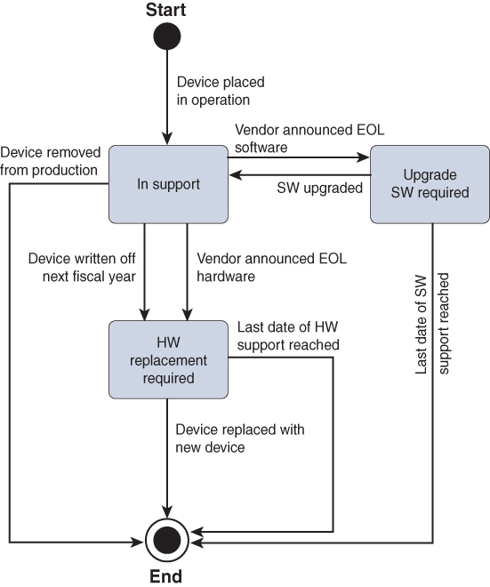
Figure 8-1 Example of a Lifecycle Management Process
This state diagram displays the “lifecycle” state of a device within lifecycle management based on a number of principles that are common within IT.
In general, each IT product consists of both hardware and software, whether this is a phone, laptop, switch, or router. Vendors provide support on both the hardware and the software. At a certain moment in time, the software might reach end of life and support is no longer provided for that software version. In that case, the state transitions from “In support” to “Upgrade SW required.” Once the software is upgraded, the state goes back to “In support.”
Similarly, if the vendor announces an end of life for the hardware of the device, the state of the device transitions to “HW replacement required.” If the support date is passed, the lifecycle of the device is ended as well, as there is no support for the device anymore.
In parallel, administrative regulations often dictate that investments above a certain monetary value need to be written off in a number of years. In other words, the costs related to the investment are often equally divided over five years instead of having the costs in a single year. If the device is written off and still in production, the support for the device will reach the “HW replacement required.”
Although this task is solely about matching the necessary requirements for the network devices to run an Intent-enabled network, this sample state diagram combined with the output of this task can be beneficial for defining and implementing a lifecycle management process.
Standardization of Campus Configuration
If you go through all the layers and functions of an Intent-Based Network from a configuration perspective, the requested Intents are translated into small pieces of configuration that are pushed onto the required network devices using automation. In other words, within IBN, the campus network consists of a standardized configuration as foundation, and the specific Intents or purposes are dynamically added to or removed from that foundation. To have a successful transformation to IBN, the configuration of the network infrastructure devices in the campus needs to be standardized.
This step is designed to convert the traditional specific port-centric configuration of switches to a policy-driven configuration with a highly standardized templated configuration of the switches and controllers in the campus network.
Migrating from Port Centric to Policy Centric
Often the campus network has evolved into a network with static and specific port configurations for the endpoints connected to that port. A port is commonly configured for a specific role, for example, an IP camera or a printer. The VLAN is configured statically as well as possibly some security features. If the printer is relocated, the operations team would need to configure the new access port the same way as the old port, and once everything was tested, the old port would be cleared from the old configuration (which is not always the case). This change would require the cooperation of the persons executing the relocation of that printer as well. This method of operation takes a lot of effort and coordination, and generally is slow. The campus network is truly port-centric based.
An alternative evolution found in the campus network is the creation of completely separate functional networks within the campus as a whole. If a network would be required for IP cameras, a separate physical network would be deployed only for those IP cameras. The ports are all statically configured for the IP cameras, and other types of endpoints are not allowed. The printers might be shared with the office network, but other types of endpoints such as sensors or logistics would each have their own physical network. Although this approach can be valid, it does introduce a number of limitations and restrictions.
For one, each network would require its own distribution switch (and possibly access switches). This adds up not only in installation cost but also in management of the network. Instead of managing a single campus network that meets all functional requirements for that branch, each network needs to be managed separately.
Second, if a new network is to be introduced on a specific location, a complete new network is built for just that purpose and added to the WAN router. This adds up to a highly complex and more difficult-to-manage network.
Third, like the previous example, relocating a printer would now not require a change of configuration, but a change of patch cables from one switch to another.
In summary, both campus network designs are not scalable and are essentially portcentric driven configurations. Without any form of standardization these networks are doomed to fail and will not be able to run as an Intent-Based Network.
However, over the past decade more and more campus networks have also introduced network access control, leveraging the IEEE 802.1X network access control standard.
The IEEE 802.1x standard provides network access control in any wired or wireless network. It consists of a number of components and several protocols. Figure 8-2 provides a schematic overview of the required components.
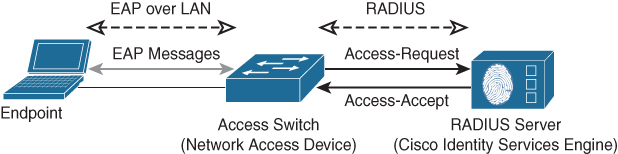
Figure 8-2 Required Components for an IEEE 802.1x-Based Network Access Control Deployment
The IEEE 802.1X protocol is explained in detail in Appendix A, “Campus Network Technologies.” In general, the switch tries to set up an authentication session with the endpoint and acts as a proxy to the central policy server using the RADIUS protocol. The RADIUS server provides the authentication (which device or user is connecting to the network), authorization (what is allowed on the network), and accounting (what has the device done) roles.
It is possible to define several authorization rules in any RADIUS server. The results of these authorization rules are added as RADIUS attributes in the Radius-Accept response back to the switch. One of the most powerful features in this authorization is the capability to dynamically perform a VLAN assignment for that specific endpoint for the duration of the session. Cisco provides a detailed guide for these types of authorization rules with the Cisco Identity Based Network Services 2.0 model.1
1 https://www.cisco.com/c/dam/en/us/products/collateral/ios-nx-os-software/identity-basednetworking-services/aag_c45-731544.pdf
In other words, if a Cisco switch receives that VLAN assignment (using a Vendor-Specific- Radius attribute), it overrides the VLAN configured on that access port with the VLAN received from the RADIUS server, essentially placing the endpoint in a different logical network. This feature enables the possibility of removing the specific port-centric VLAN assignment from the switch and placing it into the central policy server. If this transition is executed for every VLAN, the port-centric configuration of the campus network is essentially migrated to the policy server.
Cisco provides this functionality using the Identity Services Engine (ISE) solution. The Cisco Press book Cisco ISE for BYOD and Secure Unified Access, 2nd edition, by Aaron Woland and Jamey Heary, provides a great overview on how to introduce a RADIUS server into the campus network and leverage the VLAN assignment functionality to standardize the access port configuration.
If the organization does not use a network access control server, the first task within this step is to introduce that function into the campus network. The introduction of this functionality is not like a next-next-finish approach, but rather a phased step-by-step approach, which requires the cooperation of all teams inside the organization, as network access control touches all divisions (workstations, printers, servers, compute, networking).
Note
A next-next-finish approach is an analogy to how users install applications. They start the installer, click Next a number of times, and then click Finish to finish the installation, assuming that it can be installed and working correctly with little to no configuration.
Although IBN is also focused on security, in the situation where the enterprise lacks a network access control server, it is possible to only use the policy-assignment feature at first to enable the migration to a policy-centric deployment. The IEEE 802.1X access control standard can be deployed at a later stage.
Use Case: Migrating from a Port-Centric to a Policy-Centric Design
LogiServ Inc. provides network and IT services for roughly 250 employees at 30 locations in the campus network. Besides two larger campus locations, the other locations are serviced by a single access switch and an access router. The access router provides in general the Layer 3 access on each branch location using subinterfaces. Only in situations where multiple access switches are used (for example, in warehouses) is the Layer 3 terminated on the distribution switch. Traditionally when a new location needed to be added to the network, an IP network was selected from the IP plan and the router was configured with the appropriate IP space and a new access VLAN specific for that location/company. The configuration of the access switch was essentially copied from the latest location and manually adopted. Changes to locations were happening frequently but not on a daily or weekly basis. An automation tool to automate changes on the network was therefore not directly required. The network was port-centric configured.
However, as the number of branch locations was growing at a rapid pace and employees started to move between shared locations, the need for a standardized configuration was increasing to facilitate the roaming employees without any changes on the network infrastructure by the operations team.
Unfortunately, there was no budget available for a Cisco Identity Services Engine deployment; the use case was more on the automation side rather than security at first. Also, not all endpoints were able to use the IEEE 802.1X standard, and thus a different approach was taken.
As the use case was to migrate to a policy-centric network configuration and not security, the MAC address of a device can be used to identify the device and push the appropriate VLAN as authorization to the network switch. The VLAN assignment would only be required for special endpoints, such as access points, IP cameras, and printers. Fortunately, the VLAN number for these devices was the same across all branch locations.
PacketFence, an open source RADIUS server appliance, was deployed to the network. Several groups (roles) were defined, and each group would have its own VLAN assignment.
After importing the MAC addresses into the PacketFence database and enabling 802.1X with MAC Authentication Bypass on the switch, the VLANs were automatically assigned for each special device.
LogiServ clearly made a decision to start standardizing the network with VLAN assignments based on the MAC address of the devices that would require a special VLAN. It was understood that extra work was required by registering all MAC addresses of the special devices, but this weighed up against the current manual work.
The implementation of PacketFence provided the necessary capabilities to create a default access port configuration on all switches and let PacketFence override the VLAN if required.
The standardization of an access port configuration greatly improves the standardization level of the switch configuration and is a great benefit to automation and the transformation to Intent-Based Networks.
This same principle can be used with Cisco Identity Services Engine as well to convert the campus network from port centric to policy centric. For Intent-Based Networks, the preference is to deploy a Cisco Identity Services Engine as Cisco DNA Center integrates with ISE. This integration requires ISE version 2.3 or later. (At the time of writing, the ISE version 2.4 latest patch is the long-term supported stable version.)
If a network access control server is already deployed in the campus network, then use this server and introduce dynamic VLAN assignment to standardize the access port configuration of the campus network.
VLAN Numbering
The previous task within this step enables the campus network to move from static port configurations for each device to a policy-centric campus network. Intrinsic to this change is also that the VLAN numbers across the campus network need to be consistent for the same roles.
It is important (and also scalable and convenient) to use the same VLAN ID for each function of the network, so that the authorization policies inside the RADIUS server are independent of the location and thus more scalable. The access points are always connected to VLAN 2001, while management is VLAN 981, workstations in VLAN 100, and so on.
This task is used to identify VLAN usage mismatches and standardize the VLAN numbers across the campus network.
The complexity of this task is dependent on the diversity and evolution of the campus network for the specific organization. In general, the following actions can be executed sequentially to perform this task:
Step 1. Identify all VLANs used in the campus networks.
Create a table of all VLAN numbers used in the campus network across all locations. Also write down which VLAN is used for which type or group of devices. If it is known that certain endpoints are on fixed VLANs for a specific reason, make a note of that as well. Also note the VLANs that are used to connect the campus location to external WAN providers because they can also be standardized.
Step 2. Set up a unified VLAN numbering plan.
Just like an IP plan, analyze the results from the previous step and create a unified VLAN numbering plan. The key requirement is that the VLAN number is the same for each group of devices, regardless of the location.
Step 3. Define gaps/transition projects.
Use this action to create a list of old VLAN numbers and the new VLAN numbers per location. This list can be used for a project per branch location, including the appropriate change procedures.
One aspect that needs special attention is that with the introduction of standardized VLAN numbers, the VLANs will become available at all locations within the campus network. This means that all the VLANs need to have IP connectivity over the WAN as well. Use this action to introduce the necessary IP networks as well.
If a device is placed into a VLAN at a location without any IP connectivity, well, it will not have access to any resource and an incident will be raised.
Also consider when the changes are performed, if the configuration changes are deployed via an old VLAN that is to be removed, to prevent a lockout during the change. Also analyze the possibilities to change the VLAN numbering with minimal impact.
Step 4. Implement projects.
In the last step, the change procedures defined from step 3 will be implemented. Unfortunately, as the Layer 2 of a network is changed, this change will have impact on services provided to the end users. Part of the implementation project is the validation that the new VLAN plan is completely and successfully implemented, resulting in a consistent VLAN plan across the campus network.
Once these steps are completed, the VLAN numbers used within the campus network are standardized and a specific endpoint will now always be placed in the same VLAN.
Standardization of Configuration
The previous steps within this task have been focused on migrating from a port-centric configuration to a policy-centric deployment. VLAN assignments are handled by a policy from the central RADIUS server, and the VLANs are standardized across all campus locations. The configuration of a Cisco switch essentially consists of a global configuration and interface-specific configurations, such as access ports or uplinks. This step is used to standardize the global configuration for the network infrastructure devices commonly found inside the campus network.
Access Switch
In most campus networks the access switch is configured as a Layer 2 switch with a single IP address for management. Endpoints connect to the access switch, and VLANs are used to logically separate the broadcast domains and forward traffic to the distribution switch. This concept makes the access switch perfect to be standardized across all campus locations. Technologies like Spanning Tree, Switch Integrated Security Features (SISF), RADIUS configuration for IEEE 802.1X, and VLAN numbering are the same for all access switches. Only the management IP address, the switch name, and the domain name are different between all access switches. This makes the access switch a perfect fit for the definition of a first template. Once this template is created, the template can be deployed across all campus switches to standardize the configuration.
Note
A template in this context is a piece of Cisco CLI commands where specifics are defined as variables that can be entered by the operator when the template is deployed. The code in Example 8-1 is a template that can be used within Cisco Prime Infrastructure, Cisco DNA Center, and Cisco APIC-EM. The template is used to configure NTP and syslog.
Example 8-1 Template to Configure NTP and Syslog
ntp source $mgmtVLAN
ntp server $ntp6Server
ntp server $ntp4Server
ntp update-calendar
clock timezone CET 1 0
clock summer-time CEST recurring last Sun Mar 2:00 last Sun Oct 3:00
logging trap warnings
logging origin-id hostname
logging source-interface $mgmtVLAN
logging host $syslogHost
Within this template, the $ sign before a name denotes a specific variable. At the deployment of the template, the system asks the operator to enter the appropriate value for all variables in the template. The variable $mgmtVLAN describes the VLAN ID for management. Cisco DNA Center remembers the variables once deployed to a specific device.
Distribution Switch
The distribution switch in a campus network typically provides the IP connectivity to the different VLANs in which endpoints are connected. Also, the configuration of a distribution switch is also dependent on the size of each branch location (how many access switches are connected). However, a large part of the global configuration, such as the IP addressing, Spanning Tree configuration, and security technologies such as management access, can be configured using templates as well. Ideally each distribution switch will have the same set of basic templates and a single template that defines the unique aspects of a distribution switch for a specific branch location.
Wireless Network
Wireless networking is much more complex than a wired network. The primary reason is that the Radio Frequency (RF) spectrum is dynamic and each client can behave differently. Because the VLANs are standardized across the campus network, each local controller can now be standardized for several wireless settings, such as the SSIDs being broadcasted, the VLANs used, and the security configuration. The only aspect that is dynamic per location is the RF configuration. Tools such as Cisco Prime Infrastructure and Cisco DNA Center are excellent in creating and deploying a set of templates for wireless controllers to standardize the configuration of the wireless network.
At the end of this step, all switches and wireless controllers within the campus network have been configured using a minimal set of templates to standardize and harmonize the global configuration. Preferably, all access switches have the same template with only the IP address and switch name being different.
The distribution switch is a bit more complex but also capable of being standardized on portchannel numbers and other global configuration aspects.
Also, all VLANs are now available at all campus locations, and the central policy server is assigning the appropriate VLAN based on the identity of the endpoint. The campus network configuration is now prepared for an Intent-Based Network.
Introducing Assurance/Visibility
Within most enterprises large changes in the IT environment, whether a new application, hardware replacement, or a software upgrade, are executed in projects. Often these projects are resourced with external resources as the operations team is overloaded and cannot provide resources to support the project and keep an active association with the project.
Consequently, if problems arise in the project (like a special management tool is required for new hardware or an application is not working the way it is supposed to), the project team makes a decision based on the project requirements and deadlines and often cannot oversee the consequences of that decision for the operations team after the project is finished.
So at handover, the operations team is faced with those decisions (and leftovers) and needs to deal with them without control. And as the operations team was busy to start with, the new tool will probably not be used and the operations team will over time get annoyed over new projects.
To change this mind-set and behavior, a good association should exist between project teams and the operations team that will become responsible for day-to-day management after the project is finished. This association requires time from the operations team, and thus time needs to be made available from the day-to-day operations.
The network analytics component of IBN is meant to proactively support the operations team in their day-to-day tasks. It should alleviate the time pressure on the operations team so that the team can cope with more connected devices and an increasingly complex environment. The analytics component itself does not have a direct impact on how the campus network is managed other than just some information from the network devices is sent to the analytics component.
The analytics component is thus a perfect solution to quickly reduce the workload of the operations team by intelligently supporting the team during troubleshooting. The assurance component of a Cisco DNA Center (DNAC) solution is a perfect opportunity to introduce analytics to the operations team.
Use Case: How DNA Center Assurance Assists in Troubleshooting
SharedService Group provides wireless connectivity to its end users. Larger office locations leverage the use of a local controller with local breakout. At one moment incidents were reported that there were issues with the wireless network at one of the locations. In the transition to Intent-Based Networking, Cisco DNAC Assurance was enabled for a number of wireless locations. Cisco DNAC Assurance confirmed, by the client health score, that a large number of wireless clients were not connected to the network or had lost connection. Figure 8-3 shows a screenshot of that event.

Figure 8-3 Screenshot of Cisco DNAC Dashboard Related to Wireless Incident
The operator is able to zoom in to a specific moment in time to analyze a problem. But besides manual analysis, Cisco DNAC Assurance leverages machine intelligence to correlate the data against a number of known issues to proactively support the operations team in defining open issues based on the network’s configuration and behavior. For the problem at hand, an open issue was created as well. Figure 8-4 is a screenshot of an issue list that Cisco DNAC Assurance provides.
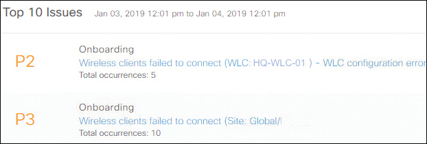
Figure 8-4 Screenshot of Open Issue List
Once the operator drills into the open issue, all information regarding that issue is displayed to the operator. The operator can quickly see how many users are affected and what the probable cause is. This is shown in Figure 8-5. As the data is smartly correlated, the operator is also shown when the issue occurred, which is shown in Figure 8-6. And to further provide support in fixing an issue more efficiently, a number of recommended actions are provided as well, which is shown in Figure 8-7.

Figure 8-5 Summary Description and Impact of an Open Issue
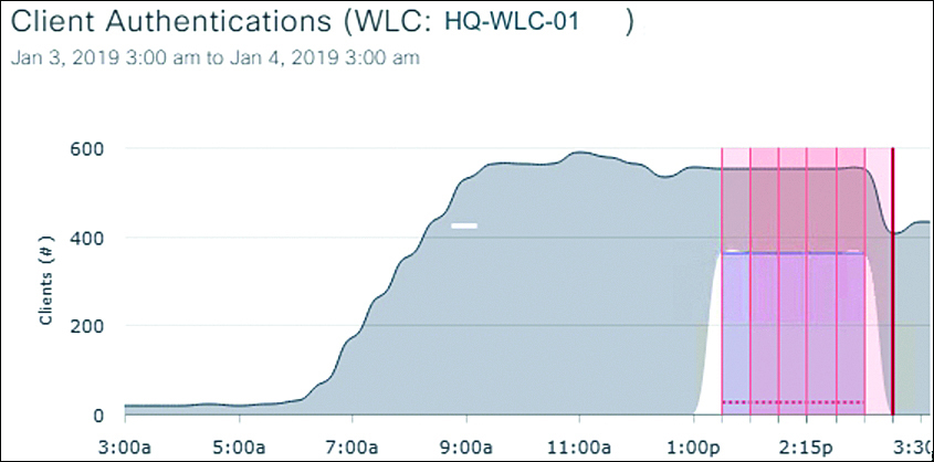
Figure 8-6 Overview of When Issues Occurred Over Time

Figure 8-7 Screenshot of Recommended Actions to Fix This Issue
The open issue (from Figure 8-4) was created by Cisco DNAC Assurance as the wireless clients were not authenticating. The operator could now quickly dive into the open issue and check whether a configuration change was made and whether there were issues with the authentication server. As both were not the case, the operator moved to step 2, which was to validate the path between the controller and the RADIUS servers. At that moment it became clear that an uplink to the WAN (which was not yet included in the monitoring by Cisco DNAC Assurance) had failed, which resulted in the reported wireless problems by the user. Resetting that link resulted in the resolution of that incident.
As you can see from the use case, the initial reported problem about the wireless network being down was not the actual problem. It was the victim of a different failure where the controller could not reach the authentication servers. Although Cisco DNAC Assurance was assuming a misconfiguration on the Wireless LAN Controller, the correlation of the data did help the operations team to isolate the problem quickly. This increase in finding a probable cause will support the operations team in reducing the workload and thus increase the opportunity to enable cooperation with the project team that implements major changes. It could even be possible that some major changes are implemented by the operations team themselves.
Cisco DNAC Assurance is an integral part of the Cisco DNAC solution. As such, a Cisco DNAC solution needs to be installed into the network. Once the Cisco DNAC solution is installed in the network, it can be enabled. The advantage of Cisco DNAC Assurance is that you can enable it without using any of its other features.
Once Cisco DNAC discovers a device and device controllability is enabled (which is on by default), Cisco DNAC will configure that device for a form of assurance, which is covered in more detail in the following sections. In the case of a Wireless LAN Controller, the certificate of Cisco DNAC is installed on the controller, the proper URL is configured, and the controller is rebooted to enable assurance. Once assurance is enabled on the controller, the controller will connect to DNAC and use model-driven telemetry to send data to the controller.
It is important to note that Cisco DNAC is not polling or subscribing to a controller, but the controller is in fact a client connecting to Cisco DNAC Assurance. This can have an impact on the network policies deployed on the network to restrict access between network devices and management tools. A number of ports are used for Cisco DNAC Assurance communication as well. It is important to check beforehand whether those communication ports are open between Cisco DNAC and the controller.
Table 8-4 provides an overview of these ports in the case of Cisco DNAC version 1.2.
Table 8-4 Overview of Ports Used Between DNAC Assurance and a Wireless Controller
Source |
SRC Port |
Destination |
DST Port |
Description |
WLC |
any |
Cisco DNAC |
TCP 32222 |
Used by Cisco DNAC for device discovery |
WLC |
any |
Cisco DNAC |
UDP 162 |
Used to send SNMP traps to Cisco DNAC |
WLC |
any |
Cisco DNAC |
TCP 443 |
Sending model-driven telemetry |
WLC/Cisco DNAC |
ICMP |
WLC/Cisco DNAC |
ICMP |
Used for checking reachability |
Cisco DNAC |
any |
WLC |
TCP 22 UDP 161 |
Used for configuration from Cisco DNAC |
An additional caveat of leveraging Cisco DNAC Assurance as a solution is that it is based on big data and machine intelligence. The sizing of Cisco DNAC must be appropriate for the environment. Also, the device needs to be compatible with Cisco DNAC Assurance, so it is important to check the device compatibility list in detail before enabling assurance. For example, AireOS code 8.5 is minimally required for assurance, but the Cisco WLC2504 and WLC5508 do not support assurance, although they can run the 8.5 code.
Within this step, the introduction of Cisco DNA Center Assurance is used to reduce the workload of the operations team. Inherent to this use case is that the organization will choose the Cisco DNA Center solution for the transformation to an Intent-Based Network. If this is not the case for a specific organization, the same principle can be leveraged using another visibility tool as long as that tool is focused and capable of proactively supporting the operations team with troubleshooting. In that manner the workload of the network operations team is reduced with a quick win of introducing an analytics component to the campus network.
Introducing Automation
If automation is not yet used within the operations team, it is another factor to greatly reduce the workload of the team besides an opportunity to allow the network operations team to gain more confidence with using automation tools. As IBN relies heavily on automation tools, the operations team needs to start relying on (and thus trusting) automation tools. If automation tools are already used, then this step can be used to increase the use of the automation tool. As this step aims to introduce automation and gain trust within the operations team, it is important to let the operations team make as many decisions as possible and allow them time to learn to cope with automation while at the same time reducing the fears of losing their jobs over automation. More on the latter aspect is described in Part III of this book.
Before jumping headfirst into the automation tool that gets the most hits on a search engine, it is wise to perform a quick analysis of requirements, including the action plan and priorities from the previous phase, to decide which tool will best fit in the current phase of the transformation.
Depending on the situation of the organization, it could be considered to use two automation tools in the transformation to IBN. If, for example, a large number of network devices need to be replaced, it is an option to start off with an automation tool already available (such as Cisco Prime Infrastructure, Cisco APIC-EM, or RedHat Ansible) and migrate to a Cisco DNA Center solution at a later stage. Similar checks and balances could result in similar decisions.
Once an automation tool is selected (or being reused), some operations can benefit from an automation tool.
Day-n Operations
One aspect of network operations that can easily leverage the power of automation to reduce the workload are day-n operations. The upgrade of switches is a task profoundly ignored by operations teams as the task to upgrade, for example, 200 switches to a new software version is often found to be cumbersome and laborious.
Automation tooling can provide a solution to this problem and provides a great way for the operations team to become familiar with automation tools. Both Cisco Prime Infrastructure and Cisco DNA Center have the capability to perform automated software upgrades, also known as SoftWare Image Management (SWIM). Although Cisco DNA Center uses a slightly different implementation of a software image management workflow than Prime Infrastructure, the concepts are similar.
Figure 8-8 provides a screenshot of SoftWare Image Management within a Prime Infrastructure solution.
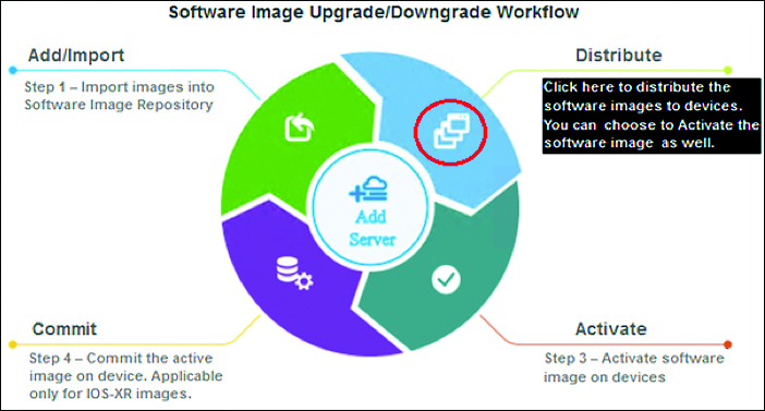
Figure 8-8 Screenshot of SWIM Within Prime Infrastructure
Both solutions leverage the concept of a repository and use a similar workflow. The repository is a location on the network where all the golden images for the different network devices are stored. Golden images (a Cisco DNAC-specific term) are those software releases selected to be deployed on the network. Other versions for the same switch type result in that switch being noncompliant. This repository can be the Cisco DNAC solution (or Prime Infrastructure) itself or an external FTP server. The following principal workflow is similar for both solutions.
Import to repository
Import the image for the switches in the campus network to the repository. Both Cisco DNAC and Prime Infrastructure have the capability to download directly from Cisco Connection Online (CCO). However, in larger enterprises, a software release could have been tested in a lab environment before releasing it in production, so it is recommended to manually import the image to the repository.
Distribute image
In this step the image from the repository is distributed onto the switches. It is possible to manually select specific switches or to allow the tool to push the image to all switches. The distribution step has the possibility to remove files from flash to create enough room for the new image to be copied. After copying the image from the repository to the switch, a verification step is executed to check whether the image was copied successfully.
Commit
Once the distribution of the image has been successful, the image can be committed. In other words, the image is configured as a boot variable in the running configuration of the switch. The software is not activated. This step can be combined with the previous step, but it is also possible (for more control) to execute this step separately.
Activate
The last step is to activate the new software image. By activating the image, Prime Infrastructure (and Cisco DNAC) saves the configuration, reloads the switch, and validates that the upgrade has been executed successfully. Besides possible caveats, a switch should return to a running state as the old version of the IOS image is still on the flash. So in case of a failure, the old image will be selected.
After the fourth step, the switches have been deployed with the new image. Although Cisco DNAC works in a similar method, the workflow is slightly different. As Cisco DNAC works with sites and network profiles, a golden image can be defined per site or globally. Once a golden image is defined for a specific switch type and role, some switches become noncompliant. Via an action in the interface, the operator can make all access switches compliant, and the above steps are executed automatically.
Use Case: Using Automation to Upgrade Switch Software
LogiServ Inc. provides IT services to a conglomerate of companies and manages approximately 40 switches. Although this is not a large number of switches, due to a history of acquisitions and mergers and specific industrial environments, approximately 5 different types of switches are deployed in the network.
In the past, LogiServ would update these switches by hand, logging in to each switch individually, copying and activating the image by copy-pasting commands in the evening or on weekends. The upgrade process would take close to two weeks of working in the evenings.
As Prime Infrastructure was used to primarily manage the wireless networks and monitor the routers, the SWIM process of Prime Infrastructure was used recently to standardize the images across all network devices.
During normal office hours the new images were distributed to the switches, where only one source image per switch was used. On a single Saturday, with announced downtime, the new images were committed and activated. Instead of working multiple evenings, a single Saturday morning was used to update all the switches in the network, including proactive comparison of the configuration after the upgrade.
As the use case demonstrates, the upgrade of switches is a typical task that benefits from automation. As this is a task that often does not have the priority of an operations team and in principle does not change the configuration, it allows the team to gain trust in automation tools and reduces the workload.
Day-0 Operations
Another aspect that can benefit from automation tooling are day-0 operations. In other words, automation can benefit the operations team greatly in the case of deploying new switches and configurations. However, this aspect is only beneficial if the number of new deployments is high—for example, because of lifecycle management to get all network devices intent ready.
If an automation tool is to be used for the provisioning of new network equipment, it also has the added benefit that the new devices will also receive a new standardized configuration.
This step leverages the capabilities of the Cisco APIC-EM and Prime Infrastructure, or Cisco DNA Center to provision configurations to new devices using Plug-and-Play (PnP). The step is explained using Cisco APIC-EM and Prime Infrastructure with an explanation of the differences based on a Cisco DNA Center workflow. A sample bootstrap configuration template follows.
In this workflow, APIC-EM’s PnP application is used in combination with DHCP from a seed device to set up the device with an initial configuration that contains enough information so that the device can be discovered by Prime Infrastructure (or Ansible). Prime Infrastructure’s templating engine is then used to deploy a standardized configuration to the device.
As for requirements, Prime Infrastructure and APIC-EM need to be installed and deployed on the network, including the required integration between Prime Infrastructure and APIC-EM. Also, within APIC-EM, the PnP application needs to be installed and active. Once these requirements are met, the following workflow can be used to automate day-0 operations using Prime Infrastructure and APIC-EM. The workflow for day-0 automation contains the following steps:
Define and import a bootstrap template.
A template that contains the bootstrap configuration is imported in a project within APIC-EM’s PnP application. This bootstrap template configures the new device with enough information, such as hostname, SSH keys, and credentials, so that the device can be discovered via Prime Infrastructure.
Enable PnP service with DHCP on seed device.
A seed device is required for PnP. This could be the distribution switch or the WAN router. On this device the DHCP service needs to be configured with the remember option and a specific DHCP option that PnP uses to discover the PnP server.
Start up switches and provide them with the bootstrapped configuration.
Once DHCP and PnP are enabled, the new switches are racked and stacked. They can now be powered on. Once the switch is booted, a PnP process is started to attempt PnP. This process will run as long as the boot process is not interrupted! So if you enter any key on the console, this process will be aborted!
The PnP process attempts to get an IP address via DHCP and will connect to the APIC-EM PnP server.
Within PnP the device will be visible within the project created in step 1. The bootstrap template is applied and the required variables are entered by the operator. APIC-EM will in turn push the configuration, and if required the proper image, to the device and configure the device.
At the end of this step the new switches have an IP address and are discoverable by Prime Infrastructure.
Discover devices in Prime Infrastructure.
Once the switches are provisioned, a discovery rule within Prime Infrastructure is (automatically) started, and the devices are discovered and added to Prime Infrastructure. This step automatically places the devices in monitoring as well.
Provision devices with appropriate template via Prime Infrastructure.
The last step deploys the appropriate configuration templates within Prime Infrastructure to the devices. These templates essentially finalize the configuration of the devices with the appropriate settings such as VLANs, logging configuration, and time servers.
After these five steps, the new devices are configured and provisioned. Although these steps might still seem to be a lot of work, the benefit of automation becomes true if multiple switches are to be configured at the same time, for example, in a new building. Field engineers can rack and stack the switches beforehand, and at a specific moment these steps can be executed for all switches by just powering them on; the operations team can perform the required changes remotely.
This process also provides the opportunity to have a more direct cooperation between projects (placing the new switches) and operations (managing the network).
Cisco DNA Center is the evolution of PnP from APIC-EM combined with templates of Prime Infrastructure. Within Cisco DNAC there is no need to define a project. New devices are placed in the inventory as new, unmanaged devices. Once the operator provisions that switch to a site, the network profile attached to that site will be applied to the switch. As the network profile contains a complete configuration for that site, including a golden image, the switch will automatically be updated to the correct image and obtain the correct information automatically.
DNA Center takes the automation of day-0 operations a step further.
The configuration template in Example 8-2 can be used for bootstrapping a new device.
Example 8-2 Sample Configuration Template for Bootstrapping a New Device
hostname $hostname
enable secret $secretPassword
service password-encryption
!
vtp mode transparent
!
vlan $MgmtVlanId
name Management
!
ip domain-name $DomainName
aaa new-model
aaa authentication login default local
aaa authorization exec default local
username admin privilege 15 secret 0 $password
!
int vlan1
 shutdown
!
interface Vlan$MgmtVlan
 description Management
 ip address $ipvAddress $ipv4Netmask
!
ip default-gateway $ipv4Gateway
!
ip tftp source-interface Vlan$MgmtVlanId
!
snmp-server group SNMP-MGMT v3 auth read SNMP-VIEW write SNMP-VIEW
snmp-server group SNMP-MGMT v3 priv read SNMP-VIEW write SNMP-VIEW
snmp-server view SNMP-VIEW iso included
snmp-server user prime SNMP-MGMT v3 auth sha $snmpAuth priv aes 128 $snmpPriv
snmp-server trap-source Vlan$MgmtVlan
snmp-server source-interface informs Vlan$MgmtVlan
!
snmp-server host $primeHost version 3 priv prime
snmp-server host $apicHost version 3 priv prime
!
ip ssh time-out 60
ip ssh version 2
line con 0
exec-timeout 20 0
logging synchronous
line vty 0 15
exec-timeout 20 0
logging synchronous
transport input ssh telnet
!
interface $Uplink1
!
switchport mode trunk
switchport trunk native vlan $MgmtVlan
channel-group 1 mode on
!
interface $Uplink2
!
switchport mode trunk
channel-group 1 mode on
switchport trunk native vlan $MgmtVlan
!
interface po1
!
switchport mode dynamic desirable
!
crypto key generate rsa mod 4096
!
Although the automation of day-0 operations might seem like quite some effort and not reduce the workload of the operations team, the opposite is true. Much effort is placed in the preparation of the day-0 operation. But once new switches are deployed, the configuration of those devices will occur semiautomatically and consistently because the same template is applied. In situations where multiple switches are to be installed, this automation step will save time.
An added benefit is that over time, the configuration of switches in the campus network will be standardized using the earlier defined templates.
Day-2 Operations
Some day-2 operations can leverage the power of automation as well. The common factor on automation is that the change itself can be defined as repeatable steps and needs to be executed on more than one switch. Changing a syslog server, adding or removing a user, and changing a RADIUS server configuration typically can benefit from an automation tool.
Use Case: Leveraging Automation for Configuration Changes
One of the companies I designed a network for was managed by three network engineers. For accounting purposes each employee was given a unique login and password. As the company grew, more network engineers were employed to monitor and manage the network. At one time, when an employee left the company, another engineer would log in to each individual switch and remove the user via the command line.
In today’s networks, automation using Python can be used to automatically connect to all switches and issue the command no user <name-of-employee> automatically. By using an input file instead of hardcoding in the Python script, the automation tool can be used for other changes as well. This script would greatly reduce the time required to execute this change.
Although day-2 operations seem to be perfect for automation, it is important to consider carefully when to start using an automation tool for these kinds of changes. The phrase “one error is human; many errors is automation” rings true. Automation can bring down a complete cloud environment if executed incorrectly. And if such a change goes awry, the potential trust for an automation tool would be reduced dramatically within the operations team. Therefore, you can use day-2 operations to gain further trust in automation within this step, but only if the automation tool is readily in place and has proven successful with other operations in the past.
Day-1 Operations
One of the primary principles of an intent-based network is that Intents are provisioned to the network devices using an automation tool. These Intents are almost always day-1 operations on the network, such as adding a VLAN or performing a change on an access list. The automation of these types of tasks is actually the end result of the transformation. As such, these operations do not quickly reduce the workload of the operations team and do not fit in this phase of the transformation.
Summary of Automation
To summarize, the introduction of an automation tool to the operations team is both essential and important in the preparation for an intent-based network. This step aims for three goals:
The introduction of an automation tool
Gaining trust of the operations team
Reducing the workload of the operations team
It is not directly required to automatically select the latest automation tool or immediately start using the automation tool that is the best fit for an Intent-Based Network (DNA Center). It is valid, based on a quick requirements and action plan check, to start the automation step in this phase using existing tools or technologies like Prime Infrastructure or RedHat Ansible.
It is important to perform this step in close cooperation with the operations team and allow for discussion and questions, as the past has demonstrated that the automation of anything will also introduce resistance and fear by the employees who execute those tasks. It is a valid strategy to take the least-liked “boring” tasks and showcase how the automation tool makes these tasks easier. Both day-0 and day-n operations are the best candidates.
Involvement of the operations team is important to reduce the fear and show the benefits. It is therefore recommended to not implement automation without members of the operations team, but rather allocate enough time and guide them to perform those changes via the automation tool. If there is a lot of resistance and fear, start with a change that is minor and does not have a great impact.
At the end of this step, there is a deployed automation tool that has proven its value, the workload of the operations team is reduced because of the tasks executed via the automation tool, and the operations team has a level of trust in the tool as well.
Risks of This Phase
Phase two encompasses all steps required to prepare the organization and the network for an Intent-Based Network. This preparation requires a number of small and big changes within both the organization and the network devices used within the campus network. Some of the steps and tasks described in this phase can take some time, depending on the agility and maturity of the organization. Consequently, some risks can be associated with this phase.
The potential long time required for this phase is probably one of the most prominent risks that can be identified. If the maturity level of the organization needs to be increased, this means that the organization needs to change and start working with documents, procedures, and so on. Changing an organization takes much more time than the introduction of a new technology. Executing organizational changes can be compared with walking on a high wire. If the pace of change is too slow, management will either lose focus (and thus commitment) or get impatient. If the pace of change is too high, employees will stop cooperating, which will make change even more difficult.
In both situations, the commitment from management can fade, and as a result the transformation to an Intent-Based Network can be canceled. Another scenario is that, due to factors external to the IT department, the initial commitment for Intent-Based Networking is put on discussion, for example, because of strain on resources, lower budget, an acquisition, and so on. In summary, because of the long time it can take to change an organization, there is a chance that the transformation will be canceled.
A lack of budget or lower revenue can also result in being unable to replace network devices in the campus network for Cisco DNA-ready equipment.
To mitigate these risks, it is important to know and actively inform stakeholders so that management stays committed. A vision and strategy from management on IBN will reduce this risk as well, depending on the maturity and perseverance of management.
Another risk identified within this phase is to prematurely end this phase and declare that the campus network is prepared for an Intent-Based Network. All steps in this phase are meant to prepare the organization and the network for a successful Intent-Based Network implementation. Failing in, for example, the introduction of a standardized configuration with a central policy can lead to unexpected results when an Intent is working for one branch location but not another. Even worse is when an automation tool is not introduced properly with the operations team supporting that kind of automation. The team will not use the tool and will still work in an overloaded work situation with reduced faith in any attempt to reduce that workload. If the steps in this phase are not completed successfully, complex and unnecessary problems will eventually occur in phases three and four. These problems will reduce the success and potential of an Intent-Based Network.
Another pitfall and thus risk is to allow all steps and tasks in this phase to be executed by (external) project teams. Although this approach is common within organizations, not involving the network operations team is a big risk.
Part of this phase is to establish trust in a new method working within the operations team. If an external project team introduces a new tool, whether it is perfect or not, the operations teams will not have the time to investigate, learn, and really use the tool.
They are used to executing per-device changes or operating in a specific way, and they will continue to do so until something really bad happens or until they are led step by step into a different way of thinking. It is a human bias that facilitates this behavior. More information on this behavior is described in Part III of this book.
It is therefore important that management allocates resources to the network operations team, so that the network operations team can execute the tasks themselves with the support of a project team. The project team must be supportive to the operations team and not vice versa.
It is self-evident that the network operations team needs to focus on operating the campus network as well. Therefore, it is a valid option to introduce a dedicated project team, in which members of the network operations team participate and have the final decision on all choices related to operating the network.
This phase cannot be compared to a next-next-finish project. Each organization is unique in its own ways, culture, and methods. In some types of organizations, a directive approach can work better than a more subtle approach. Although in general, a subtle, gradual approach is most often beneficial to all, the proverb that each war strategy is thrown away when the first bullet is shot is applicable to this phase as well. It is important to keep a sharp focus on the expected end results of this phase while mitigating the risks and adapting to the specifics of each organization. In other words, manage for the expected outcome as described in the different steps of this phase.
Summary
The second phase in the transformation to Intent-Based Networking is about preparing the campus network and the organization for an Intent-enabled network. This phase might very well be the longest phase in the complete approach as both the organization and the network are prepared. There are four steps in this phase, and it is suggested to run these steps sequentially.
Matching requirements: In this step the requirements for a successful transformation to IBN are met. These requirements are for both the organization (maturity level of organization and resource availability) as well as the network infrastructure (DNA-ready hardware and migrating from port centric to policy centric).
Standardization: The configuration of network devices is standardized, and a standardized consistent VLAN numbering plan is introduced.
Introduction of automation: Automation is introduced to gain confidence in tooling and reduce the workload on the network operations team.
Introduction of assurance: To reduce the workload on the network operations team.
This phase is probably the longest in the transformation to IBN. The predominant reason is that both the hardware needs to be DNA ready (which takes time), and the organization needs to be at a certain maturity level (which also takes time). Therefore, this phase also has a number of risks:
Lack of budget
Premature ending of this phase
Executing the required steps by an external project team
Lack of resource availability
In conclusion, these four tasks (matching requirements, standardization, introducing assurance, and introducing automation) combined make up phase two and conclude the preparations for an Intent-Based Network. The time required for this phase can be considerably long for a number of reasons. A primary reason is that the organization needs to be at a specific level of maturity in regards to IT and IT management. Most aspects must be at level 3 (processes are documented and being followed) with preferably a number of aspects at level 4, where a vision and strategy are defined and adhered to by both management and IT staff. Improving an organization’s level of maturity (and thus quality) will take a long time as it requires change within the organization.