
Part II: Transforming to an Intent-Based Network
As is made clear in the chapters in Part I, the way campus networks are traditionally designed and managed need to change. Cisco DNA as an architecture with IBN as a viewpoint will be the end goal of any campus enterprise network in order to manage and cope with all the changes and dynamics. And for new network infrastructures, it is “relatively” easy to set up the network using new equipment and a DNA Center solution. This allows the enterprise to slowly adopt SDA and IBN.
But the reality is often much harsher than the ideal world. The reality is that often there is already an existing production network, which cannot be removed and replaced with a brand new network infrastructure while the enterprise is put on hold for a number of months (or years). It’s like in the ideal world you would rebuild the factory while keeping production at the highest optimum. That is also impossible.
Also, most probably, the network operations team is already faced with demands from business to deliver faster, business not allowing downtime for scheduled updates (because then the business is interrupted), other challenges such as security incidents, being understaffed, and still keeping the network running and getting pushes from upper management to transition to the cloud as if it is a silver bullet for all IT-related problems.
But you realize that IBN is a new method of how to manage the campus network in a smarter way, reducing the strain on network design, changes, and operations. It is the way to move forward. But how do you take the first steps onto that journey, as Cisco describes it with the Network Intuitive, or in other words, a path toward IBN? And while IBN is a viewpoint and DNA is a future-ready generic network architecture, it still has to match with the uniqueness of the network you are responsible for. While each network (and its corresponding enterprise and operations team) is unique, the generic design principles, functions, and building blocks of DNA and IBN can be applied to that network while retaining its own requirements, specials, and specifications.
Consequently, each network infrastructure will transition and transform into a network based on IBN with its own unique path and way.
Chapter 5, “Intent-Based Networking,” described IBN as a perspective in detail. It also explained the functions and processes of IBN and how it is being operated. If you translate these functions and methods to an actual campus network infrastructure, then the core of IBN is that there is a basic fixed (static) campus network that does not change too frequently. Intents are defined as small but repetitive steps that are deployed on the network, and a central policy server is used to determine which policy (and thus configuration) is to be applied onto that network port.
Figure P-1 shows a minimalistic IBN-enabled campus network consisting of a distribution switch and one access switch.
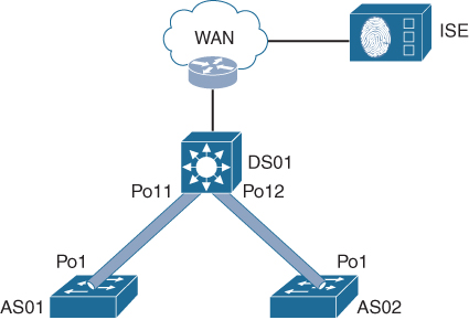
Figure P-1 A Minimalistic IBN-Enabled Campus Network
Initially there is no Intent available, and no endpoint can therefore connect. The fixed (static) basic configuration of the switches would be similar to the code examples P-1, P-2, and P-3.
Example P-1 DS01 Configuration
vlan 900
  name management
vlan 100
  name uplink-management
hostname DS01
domain-name mycompany.com
interface vlan 900
  ip address 10.1.1.1 255.255.255.0
interface vlan 100
  ip address 10.255.255.2 255.255.255.252
interface port-channel11
  switchport mode trunk
  switchport trunk allowed vlan 900
access-list 23 permit 10.0.2.0 0.0.0.255
line vty 0 15
  access-class 23 in
ip route 0.0.0.0 0.0.0.0 10.255.255.1
Example P-2 AS01 Configuration
vlan 900
  name management
hostname AS01
domain-name mycompany.com
interface vlan 900
  ip address 10.1.1.2 255.255.255.0
interface port-channel11
  switchport mode trunk
  switchport trunk allowed vlan 900
access-list 23 permit 10.0.2.0 0.0.0.255
line vty 0 15
  access-class 23 in
ip route 0.0.0.0 0.0.0.0 10.1.1.1
Example P-3 AS02 Configuration
vlan 900
  name management
hostname AS02
domain-name mycompany.com
interface vlan 900
  ip address 10.1.1.3 255.255.255.0
interface port-channel11
  switchport mode trunk
  switchport trunk allowed vlan 900
access-list 23 permit 10.0.2.0 0.0.0.255
line vty 0 15
  access-class 23 in
ip route 0.0.0.0 0.0.0.0 10.1.1.1
In the preceding examples, the access port configuration is omitted in the AS01 and AS02 configurations. All the access ports would be configured in the same way, implementing the 802.1X protocol and MAC Authentication Bypass for network access control.
At this stage no endpoint can connect to the network. If an Intent would need to be created and applied to this network, for example an Intent to allow employees on the network, then the automation function would be able to generate configuration snippets, such as shown in Example P-4 for DS01 and Example P-5 for the access switches.
Example P-4 Employee Intent Configuration for DS01
vlan 10
  name employees
vlan 101
  name handoff-employees
vrf forwarding definition IBN-01
  description employees
  address-family ipv4
interface vlan 101
  vrf forwarding IBN-01
  ip address 10.255.255.6 255.255.255.252
interface vlan 10
  vrf forwarding IBN-01
  ip address 10.2.1.1 255.255.255.0
  ip helper-address 172.16.1.10
ip route vrf IBN-01 0.0.0.0 0.0.0.0 10.255.255.5
!
Example P-5 Employee Intent Configuration for Access Switches
vlan 10
  name employees
interface PortChannel1
  switchport trunk allowed vlan add 10
!
Once these code snippets have been deployed to the network, the Intent for employees has become available. If at this stage an endpoint is connected to the network and authenticated as an employee, the access port is assigned to VLAN 10 using an authorization policy within ISE, and the employee is connected in an IP network and virtual network.
If the Intent needs to be removed, the only thing that needs to be done by the automation engine is to remove VLAN10 and the appropriate interfaces. The part of the configuration for the employee’s Intent is then removed.
This is essentially what happens within the automation part of an Intent-Based Network. A similar process occurs for SDA-based deployments with, of course, different technologies and commands.
The transformation of an existing campus network essentially has the goal to achieve this functionality for existing networks and existing policies. The transformation also includes the required tools, processes, and methods.
This part contains a description of a four-phased approach to achieve that goal for transformation from a technical or design perspective. It is focused on how the network infrastructure can be changed, in its configuration or used technology, while remaining generic enough to be applicable for most campus networks. Each chapter describes a phase in detail, including why certain steps, actions, or changes are required before moving toward the next phase. The four phases describe several elements or items that are needed to achieve that goal on the existing network. And as each network is unique, it could be that not all information is applicable to the network that is to be changed or implemented.
The transformation on any existing network toward IBN will take much more time in comparison with a brand new installation. The primary cause for this is that the changes need to be made in small steps, carefully considering several stakeholders and aspects normal in running a production campus network. Therefore, the phases in this part can be seen as steps in the strategy to move toward IBN.The chapters in this part of the book are as follows:
Chapter 7 Phase One: Identifying Challenges
Chapter 8 Phase Two: Prepare for Intent