CHAPTER 7. Network Interface Cards
SOME OF THE MAIN TOPICS IN THIS CHAPTER ARE
Choosing a Hardware Bus Type 104
The Wired for Management (WfM) Initiative 110
Load Balancing and Dual-Redundant Network Controllers 114
Troubleshooting Network Cards 119
The network interface card (NIC) is the piece of hardware that links a computer or workstation to the network media. The standard Ethernet NIC resides at the Physical level of the OSI Seven-Layer Reference Model and is the device responsible for translating data into zeros and ones for transmission on the network media for the network using electricity or light. To send data to and from other computers, the NIC’s driver software interfaces with the NIC’s hardware elements and with the protocol stack that runs on the computer.
Although this chapter concentrates mainly on network adapters that are used on Ethernet networks, be aware that there are other cards that function differently. For example, cards made for ARCnet do more than provide the functions of the Physical layer of the OSI model. They also provide the data link functionality. Token-Ring cards also work differently than standard Ethernet cards. Host Bus Adapters (HBAs) used by Storage Area Networks also incorporate more functionality on the card, thus relieving the server of having to expend CPU cycles managing some of the protocol details. However, the general troubleshooting methods discussed in this chapter can usually be applied to all these card types.
Virtually all cards manufactured today support Plug and Play (PnP), although some older operating systems do not—that would make life too simple. So, although you might find that installing a new workstation or upgrading an old one with a new network adapter card is an easy task, this might not always be the case if you are working on older equipment. In this chapter, we’ll look at the differences between card types and the items that are typically configurable for NICs. After that, we’ll list some of the methods you can use to troubleshoot network problems when you suspect that the NIC might be the problem.
Choosing a Hardware Bus Type
When you install a card in a workstation or server, whether it is a network adapter card or a SCSI disk adapter card, you insert the card into a slot that connects the card to a bus. A bus is nothing more than a communications channel that devices can use to exchange information with the computer’s CPU and memory.
Different kinds of cards can be inserted into slots to connect them to the bus in the computer. Before you make a decision on what kind of network card to purchase, you need to know what kinds of bus slots are available on the computer and which are available for use. For example, all major computer manufacturers today use the Peripheral Component Interconnect (PCI) bus (or a newer PCI standard, such as Mini-PCI in notebooks and small form-factor desktops). However, the universal serial bus (USB) is now a standard on all desktop computers made in the last five years (there are network adapters you can use with USB).
Note
While it will eventually be phased out in favor of PCI Express, another slot you’re likely to find in most systems is the Accelerated Graphics Port (AGP). You can usually distinguish this slot from other types of slots by its pin-out—only an AGP card fits into the slot—and its color, which is usually a beige or light reddish-brown. AGP slots generally are offset slightly from PCI or ISA slots (if your motherboard includes them). While some systems include both AGP and PCI-Express, newer systems may not include this slot at all. In any case the AGP slot plays no role in the installation of a NIC and is only mentioned here since you’re likely to encounter it when installing a network interface card.
The FireWire (IEEE 1394) bus, which Windows XP recognizes as a network adapter, is another competitor that offers bandwidth comparable to USB 2.0 and superior to that of USB 1.1.
PCI cards for both FireWire and USB can be purchased inexpensively if your computer does not come with them. As you read this chapter, keep in mind (1) the number of available slots you can use in an ISA/EISA bus or PCI bus, and (2) the number of devices you will use the USB or FireWire bus for. If your workstations are all newer models, you will find that only slots based on PCI technologies (PCI, PCI-X and PCI-Express) are available. About the only new PCs that use EISA or ISA slots are those which correspond to the PICMG PCI/ISA single-board computer and backplane standard.
Note
In addition to the bus types discussed in this chapter, you might occasionally hear about the MCA bus. MCA stands for Micro Channel Architecture. This bus was a proprietary standard that IBM created in 1987. Although MCA was, in most respects, superior to the other bus specifications at that time, it is not compatible with other buses. Because incorporating MCA technology required licensing it from IBM, card manufacturers never widely adopted MCA. Instead, the EISA specification was developed partly in response to the proprietary nature of MCA. Both MCA and EISA have been obsolete for several years.
Another network adapter that has just recently become an inexpensive solution for networking computers is the wireless network adapter, of which there are several types. The portability that wireless networking enables is one of its best features. There are some considerations, such as security, that are being addressed with newer standards. Wireless networks are discussed extensively in Part V, “Wireless Networking Protocols.”
In this discussion we’ll start with the older technologies (some of which are still widely used) and then go on to discuss newer network adapter cards.
ISA
The ISA (Industry Standard Architecture) bus was created in the 1980s and was the bus used by the first IBM personal computer architecture. Manufacturers adopted the term ISA as the IBM computer became a standard and vendors began to create many kinds of cards to expand the capabilities of the PC.
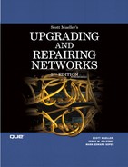
The first version of this bus provided for an 8-bit data channel. The IBM AT computer architecture used an enhanced version of the original ISA bus, allowing for data transfers at a rate of 8MHz, using a 16-bit data channel. This architecture was later expanded on, and the Extended ISA (EISA) bus was created. Although the EISA bus still operates at only 8MHz, it allows for a 32-bit path, allowing more data to be channeled through the bus. When you open a computer and look at the available slots, the ISA and EISA slots are usually the longer ones. The shorter ones are usually PCI (Peripheral Component Interconnect) slots. Figure 7.1 shows a picture of both EISA and PCI network adapter cards. The shorter footprint of the PCI card makes it easier to create PCs that have a much smaller design than in the past.
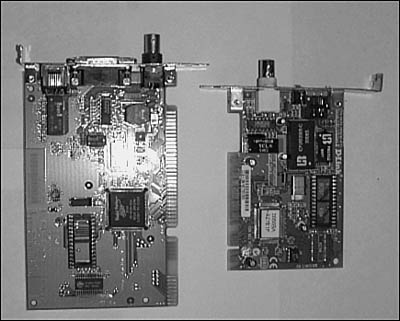
Figure 7.1. The network interface card on the left has an ISA interface, whereas the one on the right is designed for use in a PCI slot.
Note
As mentioned earlier in this chapter, most newer PCs—particularly those built since 2000—are unlikely to include ISA slots on the motherboard.
PCI
The PCI bus specifications have many advantages over previous standards, including dramatically faster data transfer rates and 32-or 64-bit-wide data paths. Devices on the PCI bus can also use a feature called bus mastering, whereby a card can take control of the bus and directly transfer large amounts of data to system memory without using the CPU. PCI has made the ISA/EISA buses obsolete.
Besides its performance advantage over the EISA bus, the PCI bus also allows for auto-configuration. A PCI card contains internal registers that hold information used for configuration when the system is booted. The kind of information that is stored in these registers includes a 3-byte class code, which indicates the card’s base class. For network cards, the value found in this register is 02h. Other possible classes include mass storage controllers (value = 01h), display controllers (value = 03h), the memory controller (value = 05h), and so on. There’s even a class represented by the value 00h, which is used for cards that were created before the definitions of class codes were finished, and a class using the value FFh, which indicates that the device doesn’t belong to any of the defined classes.
Other information contained in the PCI card’s registers tells the system-specific configuration information about the PCI card, such as IRQ (Interrupt Request, or in older documentation, Interrupt Request Line) and memory information.
Note
An IRQ is a hardware component of the computer that devices can use to send an interrupt signal to the CPU in an attempt to get the attention of the processor. For example, when a network adapter needs to transfer data from its buffer into the computer’s memory, it will use the IRQ assigned to it to notify the CPU that a request is pending. Using the IRQ line does not guarantee that the device will get an immediate response from the CPU, however. The CPU might be executing instructions that cannot be interrupted. This kind of interrupt, also referred to as a maskable interrupt, is the most used type of interrupt. Another type of interrupt is called a non-maskable interrupt, which is used to signal the CPU that a more serious condition exists and needs to be addressed. For example, a memory error or a critical hardware error is likely to generate a nonmaskable interrupt. Although the CPU can ignore a non-maskable interrupt by setting a flag, this is rarely the case.
Usually the PCI card is configured to use an available IRQ when the system detects it. If an unused IRQ isn’t found, the card can, under some circumstances, share an IRQ with another card. In that case, the system interrogates each card that shares the IRQ when the CPU receives the interrupt request. The card making the request can then communicate with the CPU to satisfy the request. Sharing IRQs should usually be done among similar devices.
The PCI bus also has several variants, such as the Mini PCI, CompactPCI, Low-Profile PCI, Concurrent PCI, PCI-X, and PCI-Express specifications, each of which is used to create a PCI-compliant bus in different computer configurations. For example, the Mini PCI bus is generally used in laptop or smaller computing devices. This PCI bus is implemented as a card that you can install in one of these smaller computer devices to enable connections to other peripheral devices, such as modems and (the topic of this chapter) network adapter cards.
Table 7.1 provides a useful overview of the different PCI bus types.
PCMCIA
Although PCI slots are used in most desktop and server computers for holding adapter cards, smaller computers, such as laptops, are another matter altogether. Because of their size, it’s not possible to include a similar setup of expansion slots that conform to conventional PCI specifications. PCI cards just won’t fit into the smaller form factor provided by laptop computers.
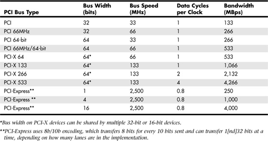
PCMCIA cards (or PC Cards if you prefer) are credit-card–size cards that can be used in laptops and other small computers. The acronym does not stand for “People Can’t Memorize Computer Industry Acronyms,” which is a popular phrase used to remember the acronym. Instead, PCMCIA is the Personal Computer Memory Card International Association, which is a nonprofit organization responsible for promoting standards for making cards for smaller computers, such as laptops. Although the first cards that were produced according to specifications by this organization were memory cards, you can now find all sorts of add-in cards for laptop computers, including network adapter cards. The term PCMCIA has been used in the past to describe these cards, but current products now use the name PC Card. Several varieties of cards currently are on the market, but most use a standard 68-pin connector. If you have to connect a laptop to the local LAN, you’ll need to evaluate this card to find one that works with your operating system. In Figure 7.2, you can see an example of an Intel PC Card network adapter.
Figure 7.2. PC Cards and CardBus cards (shown here) are much smaller than standard network adapter cards.
Note
You can use the URL www.pcmcia.org to find more information about PCMCIA cards. This trade organization has been around for many years and has been responsible for many developments in this small form factor card for use in laptop computers and, more recently, consumer devices such as digital cameras and set-top boxes for cable television. In addition, this organization also defined the standards for the PC Card and CardBus specifications, which have supplanted the older PCMCIA cards for the most part.
CardBus
In 1996, the PCMCIA organization developed the CardBus for use in small computing devices, such as laptop computers. This standard provides a 32-bit data path, which can enable PC Card devices to operate four to six times faster than earlier 16-bit cards. In addition, CardBus devices consume less power than older cards. In most cases a computer that uses CardBus is backward-compatible with older PC Card devices. CardBus cards have a gold strip on the connector (see Figure 7.2).
So, which kind of card should you choose for your networking needs? That can depend on many factors. For example, you might be limited on the kind of card by how many slots are available in the computers, and of what type. Note that if you have run out of slots for a network adapter, but have USB 2.0 ports in the system, you can plug an Ethernet adapter into a USB 2.0 port. Because USB 2.0 (also known as Hi-Speed USB) runs at 480Mbps, and Fast Ethernet runs at 100Mbps, you will not create a bottleneck for your network connection by using a USB network adapter.
Note
If you want to get a greater understanding of how the types of buses discussed in this chapter work, I recommend that you check out Upgrading and Repairing PCs, by Scott Mueller, which also is published by Que. Visit www.upgradingandrepairingpcs.com to learn more about this industry classic.
Note
Some large server installations don’t use network adapter cards. Instead, they use a technology called InfiniBand. InfiniBand was developed to solve many problems associated with I/O between the computer’s CPU/memory and external devices. By using fiber optics and a switched network, InfiniBand greatly extends the connectivity between the CPU, memory, and other components of a high-end system. You can learn more about InfiniBand at the Web site for the InfiniBand Trade Association: www.infinibandta.org. InfiniBand essentially removes I/O and disk interfaces from a server and substitutes a switched network of devices, much like those used in a Storage Area Network (see Chapter 11, “Network Attached Storage and Storage Area Networks”).
Different Cards, Different Speeds
Another factor to consider when making a network card purchase is the speed of your network. Standard 10BASE-T networks operate at 10Mbps. If you are upgrading, it is more likely that you’ll be using or upgrading to at least a 100Mbps network. If so, you’ll probably be upgrading the backbone cabling that connects your switches/routers also to a higher bandwidth, such as Gigabit Ethernet.
If you are creating a new network, simply choose 100Mbps cards. If you are upgrading an existing network, and if the cabling infrastructure supports 100Mbps, you can slowly migrate users to 100Mbps by purchasing cards that operate at both speeds. Virtually all current 10/100Mbps cards also support autosensing, which means that they can detect the speed of the network connection and adjust accordingly. When you swap out hubs or switches to upgrade to a faster network, you won’t have to worry about reconfiguring or buying new adapter cards for end-user workstations.
![]() Besides making purchasing choices for network adapter cards, plan ahead for other equipment you might need to buy, such as a new hub (or more likely a switch) to accommodate the speed of the network adapters that are used on your network. If necessary, get one that supports both speeds and autosensing (to detect the speed of the card/switch), and preferably one that works in dual 10/100 mode. For more information about switches, see Chapter 8, “Network Switches.”
Besides making purchasing choices for network adapter cards, plan ahead for other equipment you might need to buy, such as a new hub (or more likely a switch) to accommodate the speed of the network adapters that are used on your network. If necessary, get one that supports both speeds and autosensing (to detect the speed of the card/switch), and preferably one that works in dual 10/100 mode. For more information about switches, see Chapter 8, “Network Switches.”
Network Cable Connectors and Terminators
In Chapter 6, “Wiring the Network—Cables, Connectors, Concentrators, and Other Network Components,” the various kinds of network cables and connectors that can be used to create a LAN were examined. Although most older 10BASE-2 networks have already been upgraded to 10BASE-T (or faster) networks, there are still a few around that use thinnet coaxial cable with BNC connectors and terminators. If the computers on a thinnet network use “combo cards” (see Figure 7.3), you can upgrade to UTP cable without changing network adapters. These cards let you either connect a BNC T-connector to the card or use an RJ-45 jack for the newer 10BASE-T networks. However, I suspect that this will be a rare situation. If you are still operating with coaxial cables in your Ethernet network, you need to immediately turn to the upgrading section of this book and start your planning there.
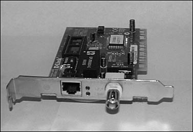
Figure 7.3. A combo card contains both a BNC and an RJ-45 receptacle and can be used on both types of networks.
The Wired for Management (WfM) Initiative
So far, this chapter has discussed some of the more typical factors to consider when choosing a network card for an upgrade or for retaining existing network cards for use in new computer acquisitions. However, depending on the size of your network, there is another factor to consider: the total cost of managing the computers on your network. The Wired for Management (WfM) initiative is a framework that most of the industry’s major players have adopted. You’ll find most of the information about WfM at Intel’s developer’s Web site (www.intel.com/design/archives/wfm/index.htm), including one particular key component: Wake on LAN (WOL) technology for network adapter cards.
To understand how WOL fits into this scheme, it’s best to start with a simple understanding of the key components of WfM:
![]() Universal Network Boot
Universal Network Boot
![]() Asset Management
Asset Management
![]() Power Management
Power Management
![]() Remote Wake-Up (Wake on LAN and Wake on Ring)
Remote Wake-Up (Wake on LAN and Wake on Ring)
Universal Network Boot
The Universal Network Boot component is based on technology that allows a computer to boot over a network and download an operating system, or other software, from a management server. The Preboot Execution Environment (PXE) technology is the key part of this component. PXE allows a computer to be remotely booted after the remote wakeup function is invoked. By using industry standard techniques, such as DHCP, TFTP, and TCP/IP, adopting PXE technology does not require extensive changes to incorporate it into new PCs. It also allows for older systems, which do not understand the extended uses of these standard protocols, to continue to function because they can simply ignore the extensions.
![]() For more information about the specifics of how PXE uses DHCP, TFTP, and TCP/IP and other protocols, see Chapter 28, “BOOTP and Dynamic Host Configuration Protocol (DHCP).”
For more information about the specifics of how PXE uses DHCP, TFTP, and TCP/IP and other protocols, see Chapter 28, “BOOTP and Dynamic Host Configuration Protocol (DHCP).”
Asset Management
The Asset Management component includes a database that keeps an inventory of software and hardware for systems on the network, and allows polling computers to get this information.
This means that a computer which hosts a database of the software and hardware components for other computers in the network can periodically query other computers on the network to ensure that those computers do indeed have the hardware/software components installed that the Asset Management software has stored in its database. This technology can detect such things as hardware additions (or software downloads performed by users).
From a security standpoint this is very important. For example, one of the major security problems in a large network is a user installing a modem (and thus bypassing all your network security mechanisms, such as a firewall). For software downloads, this component can also be an important security measure to ensure that “shareware” and other products are not downloaded to desktop computers. Any software that will be placed on desktop computers should undergo testing by your network administrative personnel before it is deployed on computers in the network.
Power Management
The Power Management component is included to provide support for the Advanced Configuration and Power Management Interface (ACPI) and for Advanced Power Management (APM), which helps reduce costs by reducing power consumption that PCs and assorted peripherals use. ACPI is a newer technology that has replaced APM. By placing a computer and its peripherals into a lower power state after a predefined time has passed with no user interaction, the computer’s electricity use is greatly reduced. This results in money saved and, in some cases, less stress on the computer’s components.
Remote Wake-Up
The Remote Wake-Up component is the component that is most relevant to this chapter. The WfM initiative supports two kinds of remote wake-ups for computers: by the LAN to which the system is connected, or through a telephone line connected to a modem (Wake on Ring). This second component is considered optional, but the capability to power up a computer by sending a specialized datagram to the computer is a key component that makes other components possible.
For example, taking inventory of existing software, or installing new software on a user’s computer, usually must be done during normal working hours. This can result in lost productivity because the user is not able to use his workstation. Performing this same function during off-hours, such as in the middle of the night, removes this expensive obstacle. One alternative is to tell users to leave their computers up and running so that you can use an automated software package to perform the inventory or software installation functions. Yet there will always be someone who forgets. And there’s the fact that while that computer is up and running, waiting to be inventoried or upgraded, electricity is being consumed. When you’re talking about hundreds of computers, that also can be an important cost factor.
To wake up a computer from a low-power state or to boot the system if it has been powered off, the network adapter must be capable of sensing a “magic packet” that is directed to it, or to use the newer “packet filtering” method.
The WOL Network Adapter Card
The network adapter that is used in a WOL situation can be a PCI card that you install in a computer just like any other network card. There is also a LAN on Motherboard (LOM) specification that places the network card function directly on the motherboard, eliminating the need for a separate card that uses up an expansion slot. The most common method at this time is to use a network card that you have to install, however.
Because the adapter card must be capable of listening to the network, awaiting a signal telling it that it’s time to wake up the computer, the card must have a power source. In Figure 7.4 you can see an example of this kind of card. The small cable is used to connect the adapter card to the motherboard to supply a power source so that the card is always listening for wake-up packets.
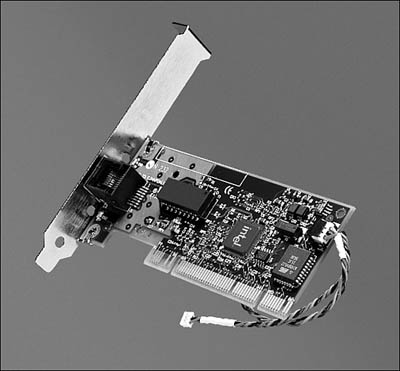
Figure 7.4. A small cable is used on some WOL cards to connect the card to the motherboard so that power can be supplied to the card.
You don’t have to do anything for motherboard solutions. The network adapter circuitry on the motherboard is already connected to the computer’s power source. However, most PCI cards available today require that you make a connection between the PCI card and the motherboard, using a small power cable supplied with the card just for this purpose. Read the documentation if you decide to use WOL cards on your network. Note that not only must the LAN card be WOL compliant, but the motherboard also must support this connection. Check the documentation!
The Alarm Clock: Magic Packets and Packet Filtering
There are two recommendations for signaling the LAN card that it’s time to wake up the computer:
![]() Magic Packets—The first method uses a “magic packet,” which is a special packet designed just for this purpose. When a specialized circuit in the network adapter card sees this packet on the network, it initiates the system wake-up.
Magic Packets—The first method uses a “magic packet,” which is a special packet designed just for this purpose. When a specialized circuit in the network adapter card sees this packet on the network, it initiates the system wake-up.
![]() Packet Filtering—In the second method, which is the preferred method in version 2.0 of the WfM specifications, the card recognizes ordinary network packets addressed to it, instead of a specialized magic packet. This second method is referred to in the specifications as packet filtering and is not to be confused with the same term when applied to firewall technology.
Packet Filtering—In the second method, which is the preferred method in version 2.0 of the WfM specifications, the card recognizes ordinary network packets addressed to it, instead of a specialized magic packet. This second method is referred to in the specifications as packet filtering and is not to be confused with the same term when applied to firewall technology.
Whichever method is used, either the computer can be booted when the LAN card receives a wake-up call, or it can simply resume normal operations if the computer has been put into a suspended low-power state without performing a complete shutdown. The preferred method is that the computer be placed in a suspended low-power state, but this is not an absolute requirement.
The “magic packet” method uses a special datagram that contains a source and destination address. The destination address can be a particular workstation’s address, or it can be a broadcast address used to wake up multiple systems. The data portion of the packet contains synchronization bytes and the workstation’s address repeated 16 times. Optional fields are also present in this datagram, but the point is that, by using this special kind of packet, the WOL network adapter to which it is addressed can begin the wake-up sequence of events. This allows it to either boot the computer or revive it from its low-power suspended state.
Should You Enable WOL?
Whether Wake on LAN is suitable for your LAN depends on how you manage your network. If you have frequent software updates or must be able to remotely manage workstations without having a technician sitting at the keyboard entering commands, you should consider using WOL and other WfM technologies. To do so you’ll also have to use management software capable of formulating and sending out WOL packets, if the network adapter requires it. Using the newer specifications, you might want to purchase cards that can wake the dead, so to speak, by detecting any network traffic directed to them.
If you manage a small network and need to make only infrequent changes, or if all of your computer systems are located in close proximity to each other, you might find WOL unnecessary since you can do things the old-fashioned way, by visiting each computer when an upgrade is needed or a problem arises.
WfM and WOL are standard on most 10/100Mbps network cards, except for the least expensive models. However, for any network in which stability is of even minor importance it’s generally not a good idea to opt for bargain basement NICs that may have problems further on down the line.
Multi-Homed Systems
Some computers need more than one network card. For example, if you have two subnets in your LAN that both need to connect to the same server, the server computer needs more than one network adapter. Although you can use a router to connect different subnets, it is probably cheaper to simply multi-home a server for a small network than to bother with the administrative overhead of configuring and maintaining a router.
In this case, the server can function both as a file or print server to both subnets and as a router. It is also possible, depending on the type of computer, to attach more than one network card to the same subnet. In any case, each network card must be set up with its own network address and host name. For example, a high-performance server might be used on an intranet to provide a WWW service and an FTP service to clients. If the server is capable of processing the requests at the required rate but the network adapter card is a limiting factor, you can install multiple cards and assign an address and host name for each service.
One popular reason for multi-homing a server today is to provide a hardware platform that can function as a proxy server for a network firewall. In this configuration, the proxy server application intercepts all traffic that passes between the two subnets to which it is connected, and acts as a go-between to enhance security on the network. The proxy server accepts service requests from one adapter and interacts with the service provider through the other adapter. The proxy server examines responses from the service and, if allowed, returns them to the requesting computer using the first network adapter.
![]() For more information about proxy servers, see Chapter 45, “Firewalls.”
For more information about proxy servers, see Chapter 45, “Firewalls.”
Load Balancing and Dual-Redundant Network Controllers
For important servers, a single network card that is used to interface with the network is a single point of failure. If the card goes bad, the costs involved can be quite high if a large number of users access the server. For many years computer manufacturers have come up with solutions to minimize downtime for important systems. The two most basic techniques that come to mind are clustering and redundancy. Clustering technology allows two or more computers to operate in a manner such that one or more computers in the cluster can service user requests at the same time, as in HP’s OpenVMS clusters. Another clustering technique, which is used in Windows 2000 Server and Windows Server 2003 clusters, uses a fail-over technique. One or more computers in the cluster are on standby and ready to take over if another member of the cluster fails.
This second technique is also an example of redundancy. For many years it has been possible to buy disk controllers that operate in a redundant fashion. Redundant node clusters, disk controllers, multiple CPUs, and other mechanisms have made the task of providing maximum uptime for computers an easy task. However, the network card remains a single point of failure.
That problem has been remedied. You can now purchase network adapter cards that work in a dual-redundant manner. That is, one card services network requests while the other waits in standby mode, checking periodically to be sure the other adapter is functioning properly. There are even versions of dual-redundant network adapters that both operate at the same time, providing a load-balancing capability as well as a fail-over mechanism.
For example, one manufacturer produces NICs that use a technique in which each NIC has its own MAC address, yet all cards that the administrator places in a “group” share the same IP address. Each group can contain from two to eight network cards, which should provide enough redundancy for almost any server. The added benefit of load-balancing to maximize network traffic throughput makes this an ideal solution for a high-end enterprise server that is used by a large client base.
Different methods can be used when load-balancing is implemented with network adapter cards. For example, one scheme is to use a round-robin technique for each packet sent out on the network. Another is to use the client’s MAC address and assign traffic for those packets to a specific controller. This technique might not be a good solution if most of the traffic is coming from a router because all the packets from the router share the router’s MAC address.
Although dual network adapters are not a factor in the desktop environment, they can provide security at that vital link in the network between an important enterprise server and the network. The cost of redundant network adapters, when compared to the expensive server hardware, makes this a cheap solution to a big problem. Because this technology has been around for only a few years, I suggest you check out several vendors, inquiring about the methods used for load-balancing and redundancy. Take into consideration also the management software, if any, that you will need to use to configure or troubleshoot the adapters.
Software Drivers
When networks were composed of mainly proprietary solutions for a particular vendor’s systems, the vendor could write a simple software driver that could handle all the functions for the protocols that the vendor chose to implement. In networks today, it might be necessary to use more than one type of protocol on a network, so now software drivers must be capable of handling more than one protocol.
In the case of servers or routers, another factor to be considered is a system that has multiple network cards installed. The driver software must be capable of distinguishing the different NICs, as well as the protocols supported on each.
The two main types of NIC software drivers that you can find today are ODI and NDIS. Predating both of these, however, is a driver called a Packet Driver, which FTP Software developed in 1986. Because different operating systems or networking software might work only with a specific kind of driver, you must be aware of the kinds of drivers that a network card can be used with if you are planning to upgrade NICs or, perhaps, undergo a more complex change, such as migrating to a new operating system. For example, if you are thinking of migrating to a Novell network, you should concentrate on devices that support ODI drivers. In a Microsoft networking environment, you would need to look for devices that support NDIS.
Packet Drivers
In the early days of PC networking, one of the main problems with network cards and protocol stacks was that they were too closely interrelated; that is, purchasing a network protocol software package meant you had to be sure that it supported the network card you were using. The operating system did not provide the code to interface with the card, but rather the specific protocol package. This, of course, meant that developers of protocol stacks had to spend lots of time developing code to support the many types of network cards that were on the market.
FTP Software developed the Packet Driver to create an interface that protocols could use to access functions the network card provides. Protocol stacks that use the Packet Driver can exist on the computer and use the network card at the same time. Previously, network drivers were tightly bound to the network card at boot time, and you had to make changes to configuration files and reboot the computer each time you wanted to use a different network protocol.
The Open Data-Link Interface (ODI)
Novell and Apple Computer developed ODI in 1989 with a goal of providing a seamless interface at the Network, Transport, and Data Link levels, as shown in the OSI reference model. The ODI specification can be divided into three components:
![]() Multi-Link Interface Driver (MLID)—This component controls communication between the network card and the link support layer. It consists of a section of code written by Novell called the Media Support Module (MSM) and the Hardware-Specific Module (HSM), written by the card vendor. The MSM provides the functions that implement standard network functions for the media types that are supported by ODI. The vendor writes the HSM code to handle the details of its particular card; the HSM code communicates with the MSM.
Multi-Link Interface Driver (MLID)—This component controls communication between the network card and the link support layer. It consists of a section of code written by Novell called the Media Support Module (MSM) and the Hardware-Specific Module (HSM), written by the card vendor. The MSM provides the functions that implement standard network functions for the media types that are supported by ODI. The vendor writes the HSM code to handle the details of its particular card; the HSM code communicates with the MSM.
![]() Link Support Layer (LSL)—This layer enables multiple protocols to exist on a single network card. The LSL is a gateway that determines to which protocol stack a network packet belongs and sends it on its way.
Link Support Layer (LSL)—This layer enables multiple protocols to exist on a single network card. The LSL is a gateway that determines to which protocol stack a network packet belongs and sends it on its way.
![]() Protocol Stack—This component gets packets from the LSL and then sends the packet to another higher-level protocol or application.
Protocol Stack—This component gets packets from the LSL and then sends the packet to another higher-level protocol or application.
Because ODI is modular, it makes writing protocol stacks or software drivers easier for third-party vendors. The code developer who works on the software to implement a protocol needs only to write to the specifications of the ODI interface, without regard to the underlying network card or the network media. The network card vendor has to worry only about writing code that can communicate with the MSM to implement the functions that are implemented by the card’s hardware.
The Network Driver Interface Specification (NDIS)
Microsoft and 3Com Corporation initially developed NDIS, with Microsoft continuing that development with more recent versions. NDIS serves the same purpose, more or less, that ODI does in that it allows for the development of software for multiple protocol stacks to exist on multiple network adapters in a single computer. The actual implementation details, however, are quite different.
In Windows NT/2000/2003/XP, transport protocols span a portion of the Transport layer, the Network layer, and a portion of the Data Link layer. Transport protocols, such as NetBEUI Frame (NBF) and TCP, are implemented by calling services in the NDIS interface. NDIS doesn’t completely hide the underlying network media from the protocol stack the way that ODI does. This limits most drivers to using Ethernet 802.3 or Token-Ring 802.5. Most drivers for ARCnet, for example, are written to take this into account and make the media look like Ethernet or Token-Ring to the software layers above.
Both ODI and NDIS provide support for each other. ODI provides a program called ODINSUP to support NDIS drivers. Windows computers come with NWLink, which is Microsoft’s implementation of the IPX/SPX protocols. Microsoft also offers an inexpensive product (Services for NetWare). In addition, Windows NT/2000/XP as well as Windows 2000 Server and Windows Server 2003 also include Client Services for NetWare, which allows Windows NT clients to access resources on NetWare servers. Gateway Services for NetWare perform similar functions using a single Windows server computer as a gateway to NetWare services. A separate product called File and Print Services for NetWare is available from Microsoft, and can be used on a NetWare client to give it access to resources in a Windows server network.
In Part VI of this book, “LAN and WAN Network, Service, and Application Protocols,” you will find more details about the various networking protocols that are available.
IRQs and I/O Ports
Although most network adapter cards support plug-and-play capabilities that allow the operating system to automatically detect and configure them, this capability is not implemented in all operating systems, such as many Unix variants. Because of this, you might find yourself having to configure a card manually when upgrading a system with a new card, or when adding other devices that might conflict with the NIC. The two main items you may have to modify are the values for the IRQ and the base I/O port.
IRQs
When a device on the computer’s bus needs to get the attention of the CPU, it uses a hardware mechanism called the Interrupt Request Line (IRQ). Hardware interrupts are executed by signaling the CPU through a set of wires that are connected to the pins that attach the CPU to the motherboard. It is a direct connection. Because various devices might need to get the CPU’s attention at any particular time, one IRQ is not sufficient. Instead, in most cases each device has its own interrupt line. When a device signals the CPU using an interrupt, it is telling the CPU that it has a processing request that needs to be satisfied as quickly as possible.
When the CPU receives an interrupt, it grants the device its attention for a short period—as long as it is not currently servicing another interrupt of a higher priority. It is also possible that the CPU is performing some task that is too critical to allow for an interrupt. When that is the case, the CPU does not allow a hardware interrupt to distract it. For that reason, this type of interrupt is called a maskable interrupt. This means that the CPU can be put into a mode in which it masks out these interrupts while it is busy on an ultra-important task, and then re-enables the interrupts when it is again capable of processing them.
The number of IRQs that are available on the system depends on the system bus type. Early PCs that were based on the ISA bus type had only eight hardware interrupts, numbered from 0 to 7, as shown in Table 7.2.
Table 7.2. ISA Bus Hardware Interrupts
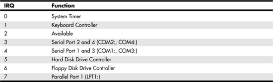
This small set of IRQs was sufficient for a small system with few devices. As you can see, only one IRQ—2—is available for an additional device in this layout. When the the 16-bit version of the ISA bus was developed, the number of interrupts doubled to 16 (numbered 0 through 15). However, to do this, two interrupt controllers were needed on the system; one of them funnels its interrupts through IRQ2. This means that there are actually only 15 interrupts available for use by other devices on the system. Table 7.3 shows the devices that usually use these IRQs.
Table 7.3. 16-bit ISA Bus Hardware Interrupts
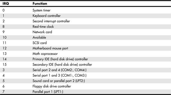
Notice that the IRQ numbers in Table 7.3 are not in numerical order. Instead, they are listed in order of priority, with those at the top of the table having a higher priority than those at the bottom. Because the additional eight IRQs were added by a mechanism that uses the original IRQ2, those IRQs all have a higher priority than IRQs 3–7. On some systems, IRQ9 is used to perform the same functions that were done by IRQ2 in the earlier design. For this reason, you might see this IRQ on a card labeled as 2, 9, or possibly IRQ 2/9.
The IRQs listed in Table 7.3 are also used by EISA and later bus systems, including the PCI family. However, starting with Windows 95, Windows began to support the IRQ sharing features built into PCI cards and slots. Depending upon the version of Windows you use on client or server systems, you might see two or more devices assigned to a single IRQ. On systems running Windows XP or Windows Server 2003, most PCI devices and cards are assigned to virtual IRQs starting at IRQ 16 rather than to traditional IRQs. Some of these virtual IRQs might be shared on some systems and by some devices, while other systems might assign a separate virtual IRQ to each PCI device.
If your computer is a plug-and-play system, particularly if it uses ACPI power management, you might find that you do not need to make any changes to the card or the system software to select the IRQ. Generally, the only way to change the IRQ used by a particular PCI add-on card is to use a different slot for the card. If you support older systems, you might need to assign ISA cards to particular IRQs. If you do, be sure to consult the documentation that comes with the card to determine which interrupts it can use and how they are set. IRQs in non-plug-and-play cards are usually set by jumpers on the card, but sometimes through a software configuration utility. A jumper consists of a set of pins that can be connected to form a complete circuit by placing a connector between them. Some ISA cards can be manually configured for IRQ and other resources, while others can be configured to run in plug-and-play mode.
Base I/O Ports
Again, if you find yourself in a situation in which your computer’s operating system does not provide plug-and-play capabilities, you might have to manually configure the value of the memory address that the network card uses to transfer data to and from the system. After the network card signals to the CPU that processing needs to be done, it uses a memory address called the base I/O port address for this purpose. Because many devices in the system might use memory port addresses, it is important to configure each device to use a different address so that any data transfers that are performed do not conflict with each other.
On most systems, 64KB of memory is set up to be used for I/O ports, so they do not represent a limited resource like the IRQ does. Consult your operating-system documentation to determine how to display the current memory assignments for this area of memory.
For example, in Microsoft Windows 2000/XP and Windows Server 2003, a utility called Microsoft System Information can be used to display various hardware and software configurations. In Figure 7.5 you can see the utility, displaying the I/O ports on a Windows Server 2003 computer. Note the other selections on the left side of the MMC window. You can check IRQs, memory usage, and other things when trying to diagnose problems with network cards and other devices.
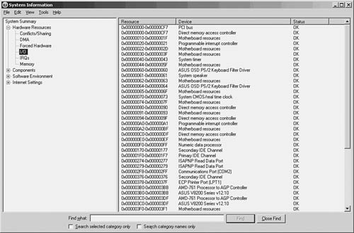
Figure 7.5. The Windows Server 2003 System Information utility can show you how I/O ports are assigned.
To run the diagnostic utility, select Start, Programs (All Programs for Windows 2003 systems), Accessories, System Tools, System Information. You can also click Start, Run; type msinfo32; and click OK. When the utility appears, select the Hardware Resources tab. Click the I/O Port selection on the left side of the MMC and your screen should look similar to that shown in Figure 7.5.
Notice that the first item listed is Conflicts/Sharing. Using this item, you can determine whether more than one device on this system is sharing an interrupt.
In addition to the base I/O port, some devices use a section of memory to buffer data temporarily. For this, they require a base memory address, which points to the start of the buffer. Your network card might or might not use the computer’s RAM, so check the documentation carefully if a conflict arises.
Troubleshooting Network Cards
When you install or replace a network adapter card and find that it does not function, there are several things you can examine to attempt to diagnose the problem. The cause might be a hardware problem with the card itself or with the computer. Or it might be the cable that links the card to the hub or switch, or the hub or the switch itself. It might be a simple problem of changing the configuration for the device. If you’re having a bad day, it might even be a combination of these things!
If you are using Windows, check the system error log using the Event Viewer to see whether any errors are being logged when the computer boots and is in the process of checking devices. Using the Event Viewer, you might find that you have a software configuration problem.
When adding a new network card to a workstation, you want to first review the documentation that comes with the card to determine what values you can use for the IRQ, base I/O port address, and so on. You might also need to look at documentation for other devices on the system because resolving a conflict might require you to change some other device instead of the network card.
The good news is that if all the cards in your system are plug-and-play compatible, you can be sure that an IRQ or memory address conflict is not causing the problem. In that case, begin troubleshooting efforts by checking the cable, hub, switch, and other hardware components that connect the computer to the network.
Checking the NIC Configuration on Linux
On Red Hat Linux 8.0 systems, if a network card is detected during setup, you are prompted to enter static IP addressing information, or to use DHCP. If you choose DHCP, and there is a DHCP server on your network, then you will probably do okay. However, if you can’t communicate on the network, there are some things you should check on Linux to ensure you have set up the system correctly for network activity.
Note
The following examples are based on using the Gnome desktop for Linux. Your choices may differ if using another desktop, such as KDE.
Finding Information About Your Network Card
To find out information such as the driver used by your network card, as well as to diagnose problems with the device, click on Start (the Red Hat for Red Hat Linux), System Tools, and then Network Device Control. In Figure 7.6 you can see that the current Ethernet device (eth0) has a status of inactive. Something is incorrect.
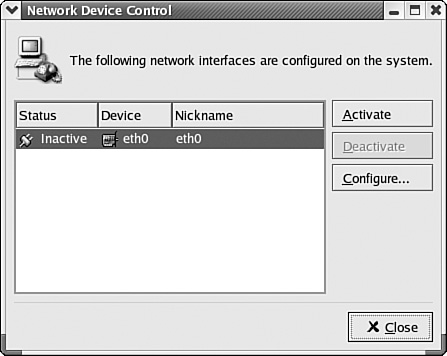
Figure 7.6. Linux will show you the network adapters connected to your system, and their current status.
Clicking on the Configure button brings up another window (shown in Figure 7.7) that you can use to further make changes to the settings for this particular network adapter card.
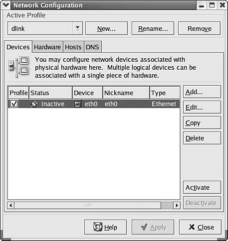
Figure 7.7. You can make changes to the settings of the network card here.
The Hardware, Hosts, and DNS tabs may be helpful, along with the Devices tab that starts this set of properties sheets. On the Hardware tab, for example, you can add or delete a particular device.
If you choose to add a device that is not recognized already by the operating system, the window shown in Figure 7.8 will appear.
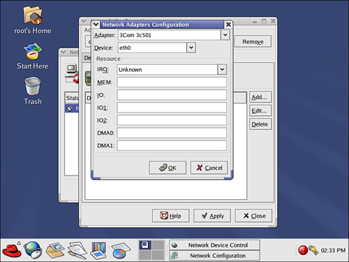
Figure 7.8. You must have the necessary technical information to install a network adapter card that is not recognized by the Linux operating system.
After you’ve filled in the necessary information, you can click OK and then exit the Network Configuration utility. You can then use the standard TCP/IP tools (such as ping and traceroute to check network connectivity).
In addition, you can always check the network configuration files (using such utilities as a text editor) if you are a more advanced user and want to be sure the system information is correct. If you are not an advanced user, at least make a backup of any file you edit, or use the GUI interfaces provided for these functions.
The files you might want to investigate include the following:
![]()
/proc/net/sockstat—To show raw statistics about TCP and UDP.
![]()
/proc/net/dev—To view statistics about a network interface.
![]()
/if_inet6—To view statistics about an IPv6 network interface.
Although these files can be used to watch what is happening on your network, there are others you should review to ensure that your network configuration is correct. Because new network vulnerabilities occur every few weeks, it is a good idea to keep these files as “high-advisability” items.
Checking the LEDs—Activity and Link Lights
All network interface cards have some combination of status LEDs (light emitting diodes) located on them. To determine the actual meaning of any LEDs, be sure to review the documentation for your specific brand and model of card. For example, some cards have an LED that is used to indicate the link status. In most cases, if the light is on, the link is okay—the NIC and the hub/switch can communicate with each other. If the light is flashing, there is a problem, which may lie in a bad cable, connectors, or even simple things such as having the transmit/receive wires reversed. NICs often use another LED to indicate network activity (when blinking rapidly, the network card is sending or receiving data). Because the standards used can vary on different network cards, refer to the manufacturer’s documentation to discover the meaning behind LEDs on your network adapter.
Network cards usually have at least one LED, which you can see on the outside of the computer—one for link status and one for network activity. Generally, if the card has only one LED (link) it should be lit if the card is capable of communicating with the hub or switch. Most switches also have an LED status light for each port, so it is a good idea to check that also. The problem might be in the hub, switch, or network card. It might even be the cable that connects them.
Tip
Today many network cards as well as switches can tell you more than just that network connectivity has been established (one LED), and that network communications are taking place (the second LED). Newer ports on both ends can let you know if the card/port is functioning in 10 or 100Mbps, half- or full-duplex mode. This can be very useful when troubleshooting slower network nodes. You should, of course, check the operating-system settings for a network device to be sure it is set for the correct mode.
If it appears that there is a problem with the link, localize the problem and determine where the fault is by trying the following:
![]() Check all connectors to be sure that they are firmly plugged into their sockets.
Check all connectors to be sure that they are firmly plugged into their sockets.
![]() Be sure that the card and the hub/switch port are set for the same type of link; that is, the switch might be set to full duplex while the card is not, or one end might be set to 10Mbps while the other is set to 100Mbps.
Be sure that the card and the hub/switch port are set for the same type of link; that is, the switch might be set to full duplex while the card is not, or one end might be set to 10Mbps while the other is set to 100Mbps.
![]() If your card supports auto-negotiation, try to enable or disable this feature on the switch or hub. If the card’s documentation indicates that it does support auto-negotiation, it might not be functioning properly. You might have to manually set the hub or switch port to the proper setting.
If your card supports auto-negotiation, try to enable or disable this feature on the switch or hub. If the card’s documentation indicates that it does support auto-negotiation, it might not be functioning properly. You might have to manually set the hub or switch port to the proper setting.
![]() Try another port on the hub or switch.
Try another port on the hub or switch.
![]() Try a different cable, preferably one that you know is in good working condition. If you are connecting directly to the hub or switch over a short distance, this should be relatively easy. If you are connecting from a switch to a patch panel to a run through the walls to a jack at a desk and then to the computer, you might have to try replacing a number of cables.
Try a different cable, preferably one that you know is in good working condition. If you are connecting directly to the hub or switch over a short distance, this should be relatively easy. If you are connecting from a switch to a patch panel to a run through the walls to a jack at a desk and then to the computer, you might have to try replacing a number of cables.
![]() Try to reseat the card in the slot.
Try to reseat the card in the slot.
![]() Try to move the network adapter to a different slot in the computer.
Try to move the network adapter to a different slot in the computer.
![]() Check the BIOS settings for the computer. Check the manual for your computer to determine whether you need to reserve certain IRQs for older adapters to keep PCI cards from trying to use the same values. In some computers it is possible to enable or disable a PCI slot by using the BIOS setup program. Be sure the slot is enabled if your BIOS supports this feature.
Check the BIOS settings for the computer. Check the manual for your computer to determine whether you need to reserve certain IRQs for older adapters to keep PCI cards from trying to use the same values. In some computers it is possible to enable or disable a PCI slot by using the BIOS setup program. Be sure the slot is enabled if your BIOS supports this feature.
![]() Substitute a card that you know is good to see if the problem still presents itself.
Substitute a card that you know is good to see if the problem still presents itself.
![]() If the network adapter is built into the system, restart the system and run the BIOS setup program to make sure the adapter is enabled. If necessary, you can disable a defective integrated NIC and substitute a PCI or USB Ethernet adapter. If none of the preceding seems to work, try the card in another computer where no problem exists. If it works there, then the problem obviously does not lie in the NIC, and you might have a software or hardware configuration problem on the computer in question.
If the network adapter is built into the system, restart the system and run the BIOS setup program to make sure the adapter is enabled. If necessary, you can disable a defective integrated NIC and substitute a PCI or USB Ethernet adapter. If none of the preceding seems to work, try the card in another computer where no problem exists. If it works there, then the problem obviously does not lie in the NIC, and you might have a software or hardware configuration problem on the computer in question.
Running the Adapter’s Diagnostic Program
Almost all cards come with a floppy disk that contains software drivers and a diagnostic program. Usually you will find that it is necessary to boot the computer into DOS to run the diagnostic program, and indeed some cards come with a floppy disk that is also DOS bootable. When using a diagnostic program like this, you should be careful that no other drivers or memory managers are loaded when you perform the test to help eliminate conflicts that can result in inaccurate results. Note that “DOS” does not mean a command-prompt window in Windows XP or Windows 2000. It means booting the computer into the actual DOS operating system. With Windows XP and Windows Server 2003, the Format command offers an option to transfer DOS files to a disk so it can be used to boot the computer into DOS mode.
The kinds of tests that can be run vary, but you will probably get a menu that allows you to run one or all of the tests that the program is capable of executing. This can include simple hardware-specific checks and loopback tests. Some cards provide for an echo test, in which two cards from the same manufacturer can send and receive packets from each other for a diagnostic test. If the card cannot pass all the diagnostic tests that the vendor supplies, and if you are sure there are no other problems (such as a bad slot in the computer’s system bus), then you probably have a bad card and need to replace it.
This method is also used for installing new network cards. Although most can be installed using the Add/Remove Hardware Wizard in the Control Panel, others need to be installed by setup programs on the floppy disk or CD that comes with the adapter.
Configuration Conflicts
If the card passes the vendor’s diagnostic tests and you can find nothing wrong with the physical components of the card, the computer system, or the hub/switch, then it is time to check the configuration of the card. Earlier in this chapter (in the section “Base I/O Ports”), you saw how the Microsoft MMC System Information utility in Windows 2000/XP and Server 2003 can be used to determine which memory address a device has been configured to use. You can also use these utilities to determine the IRQ and other configuration information for the devices installed in the computer. In Figure 7.9 you can see the Windows 2000 System Information window with the Conflicts/Sharing item selected.
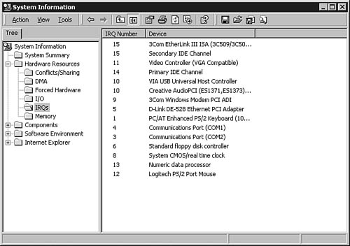
Figure 7.9. You can use the System Information MMC utility to check for device conflicts.
If you are working with a Windows NT 4.0 computer, you can use the Resources tab in the Microsoft Diagnostics utility to compare device settings. Check the Conflicting Device List field. If you find that other devices appear here, you can take appropriate action and reassign the IRQs or memory addresses as needed until all devices are functioning correctly. Reassigning these values will likely involve using software that comes with the particular adapter card. With Windows 9x, use Device Manager (a tab on the System properties sheet) to view IRQ and other hardware information if MSInfo32.exe is not installed.
Note
Remember that the PCI bus allows for the capability to share IRQs. Thus, if you notice that more than one device is using the same IRQ number, it might not really be the source of your problem. In general, only similar devices should be sharing the same IRQ. When the IRQ line signals the CPU for a shared IRQ, the system interrogates each device that shares the IRQ to determine which device is actually requesting attention from the CPU.
If you are using an older ISA card, you will probably have to use a jumper or a small switch on the card to change configuration information. If you’re using an EISA card, the ECU program can usually be used to help adjust configuration information.
For Unix and Linux users the situation is more complicated. In many older systems adding new hardware requires that you recompile the kernel and reboot. Many newer systems support plug-and-play and can recognize well-known hardware components and configure them automatically, but this is not always the case. Depending on the version of Unix or Linux, you might be able to examine configuration files to determine the interrupts and memory addresses a particular device uses. Check your system’s documentation for further information.
Because there are many releases of both Unix and Linux, your best bet when troubleshooting NIC problems is to start with the card manufacturer’s resources. Some cards can be configured by running a program that comes with the adapter, whereas others must be installed and configured using utilities the operating-system vendor supplies.
Checking the Computer’s Network Configuration
If none of the previous troubleshooting steps has uncovered the source of your problem, the problem just might lie farther up the protocol stack and might not be a problem with the hardware components. For example, if you are using a DHCP server to allocate IP addresses on the network, the computer might not have been able to successfully obtain configuration information from a DHCP server. Or, if you have configured the IP information manually and have a statically assigned address for the computer, check to be sure you didn’t mistakenly use the same address for more than one computer. Be sure that the address you assigned to the computer (and the subnet mask) is the correct one for the subnet to which the computer is attached.
After you’ve eliminated the hardware components as the problem source, there are other tools you can use to diagnose protocol and routing issues. Chapter 27, “Troubleshooting Tools for TCP/IP Networks,” covers the standard utilities that come with most TCP/IP implementations. These programs allow you to look at the actual frames flowing through the network, giving you a detailed look at what is actually going on. Even though everything else might check out okay, such as the link LEDs, your network adapter card might be sending out corrupted frames. In that case, toss it and buy a new card.
Preventative Steps to Take
Keeping track of system information for the computers in your network can make troubleshooting tasks a lot easier. For example, a spreadsheet that lists all the nodes on your network, along with configuration information, is very useful when you need to upgrade or replace a particular component. If you have this information already available before a problem arises, you will be able to devote more of your time to solving the problem. After you’ve ensured that the network card is functioning, troubleshooting is a lot simpler if you have a map to follow to determine where the network cable connects to another network device.