
CHAPTER 28. BOOTP and Dynamic Host Configuration Protocol (DHCP)
SOME OF THE MAIN TOPICS IN THIS CHAPTER ARE
Taking BOOTP One Step Further: DHCP 489
Installing and Configuring a DHCP Server on Windows 2000/2003 497
Using DHCP with Red Hat Linux 517
Configuring a Router or WAP to Provide DHCP Services 519
You should read this chapter and Chapter 29, “Network Name Resolution,” as though they were one, because they cover both sides of the coin when talking about how computers are uniquely identified on a network. This chapter deals with the specifics of how computers can be set up to automatically receive addressing and other information when they boot. This relieves the system administrator from having to manually configure each computer individually every time a global change is made. Chapter 29 discusses how other computers on the network go about determining the particular address of another computer on the network by registering themselves and querying the Domain Name System (DNS) database.
BOOTP is an old protocol. DHCP has also been around for awhile. However, DHCP is basically a protocol that builds on and expands the capabilities that BOOTP first provided. For this historical reason, and the fact that BOOTP is still in use in many networks, both are examined in this chapter. Most modern DHCP servers, including Windows 2000 and 2003 servers and the Unix/Linux family of operating systems, still support BOOTP.
What Is BOOTP?
BOOTP stands for the Bootstrap or BOOT Protocol. The standard method for booting a computer is to locate a boot block on a local drive and then go from there, so why are we discussing booting in a book that is supposed to be about networks? During the 1980s, BOOTP was developed to allow diskless workstations to boot by downloading the operating system from another network node. Many operating systems at that time used this protocol because it allowed the use of cheaper desktop workstations on the network—long before PCs became a standard desktop item. At the time, the X-Windows workstation was popular in Unix and OpenVMS networks. BOOTP was an economical way to provide an X-Windows desktop with an operating system without the need to equip the machine with disk drives and other devices not necessary for a simple client. Other types of network clients adopted the BOOTP protocol, allowing network devices to also be suitably configured by use of the protocol.
Note
The BOOTP protocol was originally defined in RFC 951, “Bootstrap Protocol,” in 1985, and further details were provided by RFC 1542, “Clarifications and Extensions for the Bootstrap Protocol,” in 1993. That RFC was made obsolete by several other RFCs, of which the most current is the proposed standard of the same name (RFC 2132). Another important proposed standard is RFC 1534, “Interoperation Between DHCP and BOOTP.”
Downloading an operating system is only one of the functions performed by BOOTP. In addition, the diskless workstation (or other client) can also obtain network addressing information. This is because the lowest-level BOOTP client is presumed to be “diskless.” It has no method to store configurable IP addressing information between power cycles.
The BOOTP protocol is not complex. Indeed, it is a simple protocol that is small and easy to implement in programmable read-only memory (PROM) chips. The following are some important features of BOOTP:
![]() A simple request/reply mechanism is used. The same packet format is used for both requests and replies.
A simple request/reply mechanism is used. The same packet format is used for both requests and replies.
![]() The UDP protocol is used to carry messages (ports 67 and 68, the same as are used by DHCP).
The UDP protocol is used to carry messages (ports 67 and 68, the same as are used by DHCP).
![]() Using relay agents, BOOTP exchanges can occur across routers.
Using relay agents, BOOTP exchanges can occur across routers.
![]() BOOTP can supply the client with an IP address, a subnet mask, and a default gateway. A BOOTP server can also give the client name of a trivial FTP server (TFTP) and a filename that can be used to download an operating system. This TFTP server is especially important for diskless workstations, as well as network devices that need to download an operating system. The trivial FTP server, which is a stripped-down simple version of FTP, is covered in Chapter 25, “Basic TCP/IP Services and Applications.”
BOOTP can supply the client with an IP address, a subnet mask, and a default gateway. A BOOTP server can also give the client name of a trivial FTP server (TFTP) and a filename that can be used to download an operating system. This TFTP server is especially important for diskless workstations, as well as network devices that need to download an operating system. The trivial FTP server, which is a stripped-down simple version of FTP, is covered in Chapter 25, “Basic TCP/IP Services and Applications.”
![]() Another protocol, the Reverse Address Resolution Protocol (RARP), operates at the second layer of the OSI network model and is also capable of providing an IP address to another node that is booting on the network. However, RARP is very limited. For more information about RARP, see Chapter 24, “Overview of the TCP/IP Protocol Suite.”
Another protocol, the Reverse Address Resolution Protocol (RARP), operates at the second layer of the OSI network model and is also capable of providing an IP address to another node that is booting on the network. However, RARP is very limited. For more information about RARP, see Chapter 24, “Overview of the TCP/IP Protocol Suite.”
Format of the BOOTP Packet
The client and server share a common packet format. This packet is passed to UDP (the User Datagram Protocol) and encapsulated inside a UDP packet. The UDP and IP headers are added, and the information is finally passed to the Data Link and Physical layers for transmission on the network medium.
![]() The IP and UDP protocols are also discussed in greater detail in Chapter 24.
The IP and UDP protocols are also discussed in greater detail in Chapter 24.
The fields of the BOOTP packet are used for the following purposes:
![]() Opcode—This 1-byte field has a value of either zero or one. If set to a value of one, the packet is a request from a client to a BOOTP server (or a DHCP server, as explained later). If the value is zero, the packet is a reply from a server to the client.
Opcode—This 1-byte field has a value of either zero or one. If set to a value of one, the packet is a request from a client to a BOOTP server (or a DHCP server, as explained later). If the value is zero, the packet is a reply from a server to the client.
![]() Hardware Type—Values in this 1-byte field are used to designate different kinds of hardware, different computer types, or network device types, for example. A value of one in this field indicates that the underlying hardware type of the network is 10Mb Ethernet, whereas the value of 32 is used for the emerging technology known as InfiniBand. You can find the full list of values at
Hardware Type—Values in this 1-byte field are used to designate different kinds of hardware, different computer types, or network device types, for example. A value of one in this field indicates that the underlying hardware type of the network is 10Mb Ethernet, whereas the value of 32 is used for the emerging technology known as InfiniBand. You can find the full list of values at www.iana.org/assignments/arp-parameters.
![]() Hardware Address Length—This 1-byte field indicates the number of bytes that the client hardware address field contains. For Ethernet, this value is six because it takes 6 bytes to represent the 48-bit Media Access Control (MAC) address used by Ethernet network cards.
Hardware Address Length—This 1-byte field indicates the number of bytes that the client hardware address field contains. For Ethernet, this value is six because it takes 6 bytes to represent the 48-bit Media Access Control (MAC) address used by Ethernet network cards.
![]() Hop Count—This 1-byte field is always set to zero by the client, though the BOOTP server uses this field when relaying BOOTP requests across routers.
Hop Count—This 1-byte field is always set to zero by the client, though the BOOTP server uses this field when relaying BOOTP requests across routers.
![]() Transaction ID—This is a 4-byte field that is a unique 32-bit integer the client sets so that it can match up replies from the server to the requests the client has sent.
Transaction ID—This is a 4-byte field that is a unique 32-bit integer the client sets so that it can match up replies from the server to the requests the client has sent.
![]() Seconds—This 2-byte field is expressed in seconds and is filled in by the client with a value indicating the time that has elapsed since the client started the boot process. This value can be used by secondary servers to recognize that the client’s primary server is not responding. In that case, a secondary BOOTP server can make an attempt to satisfy the request.
Seconds—This 2-byte field is expressed in seconds and is filled in by the client with a value indicating the time that has elapsed since the client started the boot process. This value can be used by secondary servers to recognize that the client’s primary server is not responding. In that case, a secondary BOOTP server can make an attempt to satisfy the request.
![]() Flags—In the original specifications for BOOTP, this 2-byte field was not used. However, in RFC 1542 this field was set aside to store flag bits. Only one has been defined so far. The most significant bit in this field is used as a Broadcast flag. The remaining bits are not yet defined and should be set to zeros.
Flags—In the original specifications for BOOTP, this 2-byte field was not used. However, in RFC 1542 this field was set aside to store flag bits. Only one has been defined so far. The most significant bit in this field is used as a Broadcast flag. The remaining bits are not yet defined and should be set to zeros.
![]() Client IP Address (ciaddr)—If the client already knows its own address (which is explained shortly), it will fill in that address in this 4-byte field. In most cases the client does not know its own IP address (because that’s one of the main things BOOTP is used to supply to the client), and in cases like these the value for this field should be zero.
Client IP Address (ciaddr)—If the client already knows its own address (which is explained shortly), it will fill in that address in this 4-byte field. In most cases the client does not know its own IP address (because that’s one of the main things BOOTP is used to supply to the client), and in cases like these the value for this field should be zero.
![]() Your IP Address (yiaddr)—This field is used by the BOOTP server to supply an IP address to a client requesting one. It also is a 4-byte field, the number of bytes needed to store an IP address. Although the client can fill in the ciaddr field with a requested address, this field contains the address the DHCP server returns to the client to use.
Your IP Address (yiaddr)—This field is used by the BOOTP server to supply an IP address to a client requesting one. It also is a 4-byte field, the number of bytes needed to store an IP address. Although the client can fill in the ciaddr field with a requested address, this field contains the address the DHCP server returns to the client to use.
![]() Server IP Address (siaddr)—The BOOTP server fills in this field, usually placing its own address here.
Server IP Address (siaddr)—The BOOTP server fills in this field, usually placing its own address here.
![]() Gateway IP Address (giaddr)—If a BOOTP proxy server is being used, the address in this 4-byte field is the address of the router or other device performing the proxy function. Proxy BOOTP services are discussed later in this chapter. Note that this is not the address the client should use as a default gateway for TCP/IP configuration (though it could be the same). This field is used only to relay BOOTP requests across routers to and from the actual BOOTP server. The default gateway information is supplied in BOOTP options, described later in this chapter (see the section “Enabling the DHCP Relay Agent”).
Gateway IP Address (giaddr)—If a BOOTP proxy server is being used, the address in this 4-byte field is the address of the router or other device performing the proxy function. Proxy BOOTP services are discussed later in this chapter. Note that this is not the address the client should use as a default gateway for TCP/IP configuration (though it could be the same). This field is used only to relay BOOTP requests across routers to and from the actual BOOTP server. The default gateway information is supplied in BOOTP options, described later in this chapter (see the section “Enabling the DHCP Relay Agent”).
![]() Client’s Hardware Address (chaddr)—If the client already knows its own IP address, it will place the IP address into this 4-byte field. The client must fill in this required field because the typical BOOTP server uses it in an index of values it keeps track of for its clients.
Client’s Hardware Address (chaddr)—If the client already knows its own IP address, it will place the IP address into this 4-byte field. The client must fill in this required field because the typical BOOTP server uses it in an index of values it keeps track of for its clients.
![]() Server Hostname (sname)—This field can be up to 64 bytes in length and contains a null-terminated ASCII string of characters that represent the server’s hostname on the network. This hostname can be a simple hostname or a fully qualified domain name (FQDN). This is an optional field.
Server Hostname (sname)—This field can be up to 64 bytes in length and contains a null-terminated ASCII string of characters that represent the server’s hostname on the network. This hostname can be a simple hostname or a fully qualified domain name (FQDN). This is an optional field.
![]() Boot Filename (file)—This field can be up to 128 characters in length and is used to supply the client with the filename it can download and use to boot. The value here is also a null-terminated string and includes the full path the client needs in order to locate the file.
Boot Filename (file)—This field can be up to 128 characters in length and is used to supply the client with the filename it can download and use to boot. The value here is also a null-terminated string and includes the full path the client needs in order to locate the file.
![]() Vendor-Specific Area—These 64 bytes are set aside to store vendor-specific optional information. The items are listed in Table 29.1 in the section “BOOTP Vendor-Specific Information Options.” The first four octets in this field will be a “magic cookie.” The last octet is the “End” tag, the value 255.
Vendor-Specific Area—These 64 bytes are set aside to store vendor-specific optional information. The items are listed in Table 29.1 in the section “BOOTP Vendor-Specific Information Options.” The first four octets in this field will be a “magic cookie.” The last octet is the “End” tag, the value 255.
The client’s hardware address (technically called the Media Access Control address, or MAC address) that is placed in the BOOTP packet is the same hardware address that will be found in the Ethernet frame that delivers the packet. However, after the Ethernet frame is received, the lower-level header information (such as the client’s hardware address) is stripped off before the remaining packet is passed up through the IP and UDP layers. At the point where the BOOTP protocol begins to examine the packet, the Ethernet frame header information is not available in most TCP/IP stacks. For this reason, the hardware address is duplicated inside the BOOTP packet. Remember that the RARP protocol is a link-layer protocol, so it can retrieve the client’s hardware address from the Ethernet frame, something most implementations of BOOTP cannot do.
Note
For those who are interested in the nitty-gritty details, the packets discussed here are transmitted on the wire in the order shown in the figures in this chapter. Additionally, the individual bytes are sent with the leftmost bit being the most significant. For multi-octet values, the most significant octet is transmitted first. This information might help you when diagnosing problems on the network using a LAN analyzer or other methods to intercept and interpret network packets.
The BOOTP Request/Reply Mechanism
Because it is usually implemented in a read-only memory (ROM) chip, the BOOTP protocol client is a simple, concise bit of code. The exchange of UDP messages between the client and the BOOTP server consists of a series of requests and replies. The same packet format is used for both types of messages with an Opcode field used to indicate whether the message is a request from the client or a reply from the server.
The following basic steps are involved in obtaining information from a BOOTP server:
1. The client sends a broadcast message at the link-layer level because the client at this point is unaware of its own IP address or that of any BOOTP server that might be on the network. In the IP header information for the request, the client usually sets the source IP Address field to 0.0.0.0 and the destination address to 255.255.255.255. Because this is a UDP packet being sent through IP, the client sets the destination UDP port number to 68 (the BOOTP server port) so that a listening server will know to intercept the packet. The Transaction ID field that the client places in the BOOTP request packet is used by clients to sort out which replies are meant for them. The first 4 bytes of the vendor-specific information area should be set to a magic cookie.
Note
A magic cookie is a method used by BOOTP to tell the server what kind of format to use when creating a reply for a client’s request. The magic cookie usually is the value 99.130.83.99 but can be a vendor-supplied value. The magic cookie is usually used to indicate that the vendor-specific area contains information for the server to examine. The remaining information in the 64-byte vendor-specific information is defined as a series of tags followed by a length field and then, in most cases, a variable-length field of information.
2. If the broadcast flag is set, the server next broadcasts a reply that contains the client’s IP address, the server’s own IP address, and other requested information.
3. If the broadcast flag is not set, the server can send a unicast address using the client’s IP address to the address supplied by the client. The server should always check the Client IP Address (from Client) field set by the client to be sure it is not the default value of 0.0.0.0. If it is not, then, depending on the implementation, the server will set the Client IP Address (from Server) field to the same value and send a directed (unicast) packet back to the client. However, note that this can vary from one implementation to the next, and the server might decide to override the client’s requested IP address and substitute another.
4. Another possibility that occurs when using a router or other host to act as a proxy relay agent is that the Default-Gateway server field will be filled in. In this case, the server knows to use this field to send a directed (unicast) packet to the router or other device that is relaying the message instead of trying to broadcast or send the packet directly to the client using the client’s address.
In step 2, even though the client might be capable of determining what it thinks its own IP address should be—by saving it to a disk file in the case of a workstation that does have that capability, for example—the server can choose to return a different IP address to the client. In that case, the client should stop using its previous IP address and accept the new one from the server. There is some disagreement in the literature about this situation, and you might find that it varies from one implementation to another. For example, some vendors allow the client to specify the address it wants to use, ignoring the one supplied by the server. In this type of situation, the client is usually using the BOOTP server to obtain other configuration information, such as a boot filename or vendor-specific items, when it already knows what its own IP address should be.
BOOTP Vendor-Specific Information Options
In addition to supplying a network node with an IP address and a boot filename (and the server from which the file can be retrieved), 64 bytes are reserved in the BOOTP Reply/Request packet that can be used to supply additional configuration information to the client. The client can also use the options fields to request certain information from the server.
The options used by BOOTP are a subset of those now incorporated into DHCP. Those listed in this section apply, therefore, to both BOOTP and DHCP. These options are defined (and discussed in greater detail) in RFC 2132, “DHCP Options and BOOTP Vendor Extensions.”
The format for data in the options field is standard:
![]() Option Code—This 1-byte field contains a code that identifies the particular option. The value of 0 is used for padding and the value of 255 is used as an end marker. Note that Option Code values from 128 to 254 are reserved for site-specific options.
Option Code—This 1-byte field contains a code that identifies the particular option. The value of 0 is used for padding and the value of 255 is used as an end marker. Note that Option Code values from 128 to 254 are reserved for site-specific options.
![]() Length Octet—This 1-byte value specifies the length of the option data to follow. This length does not include the Option Code or the Length Octets.
Length Octet—This 1-byte value specifies the length of the option data to follow. This length does not include the Option Code or the Length Octets.
![]() Variable-length optional configuration data—This data depends on what kind of information the option supplies.
Variable-length optional configuration data—This data depends on what kind of information the option supplies.
As noted earlier, the value of 255 marks the end of an options list in the packet.
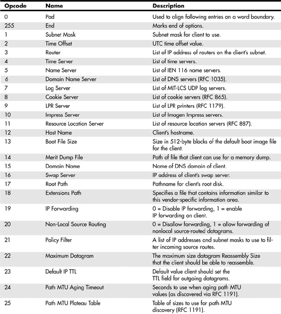
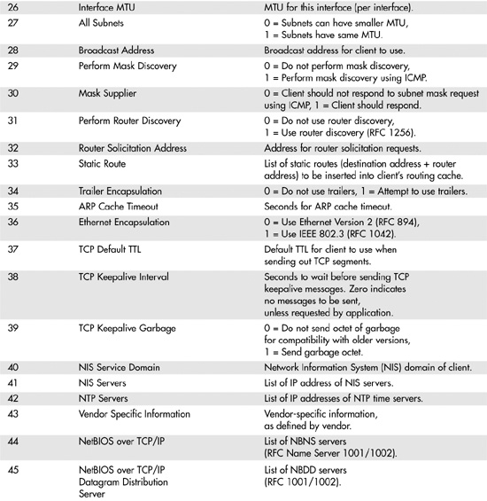
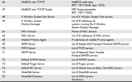
RFC 2132 defines a large number of options that can be used. Table 28.1 lists those that apply to both BOOTP and DHCP.
Table 28.1. Definition of BOOTP Vendor Extension Opcodes
Downloading an Operating System
After a client has obtained the data needed to configure itself for network access, it can use the boot file information supplied by the BOOTP server to locate and download an operating system. The BOOTP protocol only gives the name and path that can be used to locate the file. BOOTP does not perform any other functions to assist the client in obtaining a copy of the file. Instead, the client uses the Trivial File Transfer Protocol (TFTP) to retrieve the file.
![]() The Trivial File Transfer Protocol is discussed more fully in Chapter 25.
The Trivial File Transfer Protocol is discussed more fully in Chapter 25.
TFTP, like BOOTP, is a simple protocol to implement, making it easy to create client code that can be stored on a chip or embedded in a device’s firmware. There is no exchange of authentication information, such as a username and password, between the client and the TFTP server. Instead, the client simply requests a copy of the file and it is sent to the client on a packet-by-packet basis with the client acknowledging each packet. This start-stop, single-packet exchange method is slower than that which could be accomplished using TCP, but it is not intended for everyday file transfers. TFTP is more than adequate for downloading operating-system code during the boot process.
After the file has been downloaded to the client, it is executed and the client boots to become a full-fledged member of the network.
Taking BOOTP One Step Further: DHCP
Even though diskless workstations are a small percentage of the total number of network nodes in the world today, the concept of receiving configuration information from a central server has not gone away. The Dynamic Host Configuration Protocol (DHCP) was developed after BOOTP as a means for providing a workstation (or any other network device) not only with basic configuration information, but also with a lot of other configuration information, including the capability to add vendor-specific items to the networked computer. DHCP is an extension of the BOOTP protocol, and the relevant RFCs require that a DHCP server be backward compatible with BOOTP clients. This means that you can use a DHCP server on a network that contains newer clients that understand this protocol as well as older clients that still use BOOTP. Like BOOTP, DHCP uses UDP. Messages are sent to port 67 on the DHCP server. Messages from the server are sent to the DHCP client’s UDP port 68.
Note
The Dynamic Host Configuration Protocol is discussed in several RFCs. RFC 1541, “Dynamic Host Configuration Protocol,” was an early document, and RFC 2131, also titled “Dynamic Host Configuration Protocol,” further clarified the protocol. RFC 2131 added a new message type (“DHCPINFORM”), extended the classing mechanism to include vendor-specific classes, and removed the requirement for a minimum lease time. In addition, RFC 1533, “DHCP Options and BOOTP Vendor Extensions,” provides for various options to be included in either BOOTP or DHCP packets. RFC 1533 was updated by RFC 2132, which has the same title. You might notice that some of these RFCs were mentioned earlier in this chapter. This shows the close relationship between BOOTP and DHCP.
DHCP supports various configuration message options that a server can offer as a resource to a booting network node. This includes all the standard IP configuration information, such as IP address, subnet mask, and default gateway. The original BOOTP did not include all the options that were listed earlier in Table 28.1. BOOTP (and DHCP as well) has been augmented over the years to allow for more flexibility and to allow for a larger exchange of configuration data between the client and the server. RFC 1533, “DHCP Options and BOOTP Vendor Extensions,” added to the options that were first described in RFC 1497 and includes options for both BOOTP and DHCP. RFC 2132 superceded RFC 1533.
Note
If you want to find out about developments with regard to DHCP, you might want to look at the Web site www.dhcp.org. This unofficial site contains links to recent developments as well as links to the RFC documents that relate to DHCP.
Unix users also can use another Web site to download a free version of DHCP. The Internet Software Consortium has developed reference model implementations of DHCP and DNS (BIND) that you can compile on your local system. Visit the consortium’s Web site at www.isc.org. This site also sponsors an email mailing list for DHCP topics. You can subscribe or unsubscribe from the main page. The latest version of DHCP available at this Web site at the time of this writing is version 3.0.3, which was released on July 22, 2002. This version fixes serious vulnerabilities that were part of previous versions.
RFC 2131 provides for three mechanisms that DHCP servers can use to provide addressing information to clients:
![]() Automatic allocation—DHCP simply assigns a client a permanent address.
Automatic allocation—DHCP simply assigns a client a permanent address.
![]() Dynamic allocation—The most widely used mechanism, this method leases the address to the client for a certain amount of time, until the client wants to abandon the lease (that is, the workstation shuts down), or until the lease time expires and is not renewed by the client.
Dynamic allocation—The most widely used mechanism, this method leases the address to the client for a certain amount of time, until the client wants to abandon the lease (that is, the workstation shuts down), or until the lease time expires and is not renewed by the client.
![]() Manual allocation—Typically used by the administrator to manually enter addresses into the DHCP server’s database for computers or other devices.
Manual allocation—Typically used by the administrator to manually enter addresses into the DHCP server’s database for computers or other devices.
The dynamic method is the most useful in a network consisting of a large number of client computers that do not require a static address assignment. Using the dynamic method, the administrator can set the time limit for leases. Before a lease expires, the client will attempt to contact the server to renew the lease. If that fails, the client will seek another server from which it can obtain an IP address lease. This mechanism allows for IP addresses to be conserved when the network topology changes frequently. If an address is not being used because a workstation is down or has been moved to another subnet, the lease will eventually expire and the address can be reused.
Note
So what happens when there is no DHCP server when a client attempts to attain configuration information? Automatic Private IP Addressing (APIPA) can solve this problem for Windows 98, 2000, and later versions, as well as MacOS 8.5 and later and recent Linux versions. The computer sends out the standard DHCP packet. If no response is received, the computer will assign its own configuration information automatically. The address range used is 169.254.0.1 through 169.254.255.254. The subnet mask is set to 255.255.0.0. Note that this range of IP addresses is not valid on the Internet, and is intended for use only on a LAN. If you connect to the Internet using a router (or a cable or xDSL modem for a SOHO office), then you will need to configure your router to use Network Address Translation (NAT) so that the router can translate between this private address space and the IP address used on the Internet. Most SOHO routers are already configured to use NAT, so you won’t have to do anything. For more information about NAT, see Chapter 45, “Firewalls.”
APIPA is ideal for a small network. Just set your network configuration to automatically obtain IP configuration information and forget it. For more information about APIPA, see the section near the end of this chapter titled “What Is APIPA?”
These three methods are not exclusive. For example, for most situations it is easy to configure a desktop client to obtain network configuration information automatically using DHCP and then simply boot the client. Yet, for servers that need a static address, such as file/print servers, DNS servers, or Web servers, the administrator can place a manual entry in the server’s database so that the DHCP server will always provide the same address when the server boots.
Alternatively, it’s still perfectly okay to configure the server manually with static information and then mark the address as allocated (or reserved) on the DHCP server so that it won’t try to use the address. When using a small SOHO router with a cable/DSL modem, you can usually specify the range of addresses to be used or excluded. One instance in which you might want to do this is when using a Windows domain, whether it be Windows NT/2000 or Server 2003. A domain controller needs to have a static address, whereas the clients do not. Simply assign the static addressing information for the domain controllers and exclude these addresses from being assigned by NAT. Configure the clients to use automatic configuration (NAT) and the domain controllers to use static information.
Another note of interest is that cable/DSL providers also often turn to NAT. There are simply not enough IP addresses to assign every single computer and networking device in the world a unique address any more. So the Internet provider you use has a set of valid IP addresses, which are used to provide a connection to the Internet for the ISP’s clients. The clients are then assigned addresses by the ISP via NAT. And then if you use a cable/DSL modem router a second layer of NAT is used.
Note
A lease from a DHCP server is not as transient as it might seem at first. For example, when a client shuts down for a short period and then reboots, it is not automatically assigned a different IP address than it acquired during its previous lease. Instead, most DHCP servers keep track of IP addresses and the lease time. When a client reboots, it is reassigned the same IP address as long as no other client is using the address. Likewise, when the DHCP server itself is rebooted, all information should be retained in its database so that on reboot it will be able to continue to track existing leases or issue new ones.
However, keep in mind that if you move the client computer to a subnet that is served by a different DHCP server, the computer will be assigned an address from the pool of addresses available to that server and valid on the new subnet, and will thus obtain a new address that is valid on that particular subnet. On the same topic, if you have a server (such as a domain controller) that uses static configuration information, you’ll have to change that when moving the server to a different subnet.
DHCP servers are built into many network devices, including most routers, wireless access points (WAPs) with integrated routers, and cable modems. DHCP and other functions on these devices are generally configured through the device’s built-in web server.
![]() For information about configuring a router’s DHCP server, see “Configuring a Router or WAP to Provide DHCP Services,” p. 519.
For information about configuring a router’s DHCP server, see “Configuring a Router or WAP to Provide DHCP Services,” p. 519.
The DHCP Packet Format and Additional Options
Similar to BOOTP, DHCP uses a request/reply mechanism, and the packet format is almost the same for both to provide for backward compatibility. The layout of the packet used by DHCP looks very much like the layout of the BOOTP packet, with a few exceptions. The first 11 fields are the same. However, the last field, which is called the Vendor Extensions area in the BOOTP packet, is called the Options field in the DHCP packet. The format of the options is the same as it was for BOOTP. However, some of the options that are defined in RFC 2132 are specific only to DHCP. The options available for use with BOOTP clients are a subset of those available for use with DHCP clients. Although this field was limited to 64 bytes in the BOOTP packet, it now is a variable-length field that has a minimum of 312 bytes for DHCP options.
Additional Options Available for DHCP Servers
Following is a listing of the options that can be used for both types of clients. This list includes additional options defined in RFC 2132 that can be used, in addition to those found in Table 29.1, with DHCP servers and clients. The options listed here are not for use with BOOTP clients.
![]() Requested IP Address (Opcode=50)—The client can use this field to request a specific IP address.
Requested IP Address (Opcode=50)—The client can use this field to request a specific IP address.
![]() IP Address Lease Time (Opcode=51)—The client can use this field to request a particular lease time. The server can use this field to fill in the lease time it is willing to offer. The value used in this field is expressed in seconds.
IP Address Lease Time (Opcode=51)—The client can use this field to request a particular lease time. The server can use this field to fill in the lease time it is willing to offer. The value used in this field is expressed in seconds.
![]() Option Overload (Opcode=52)—This option enables the server to use the fields originally allocated in the DHCP packet for the server name and filename fields to store options. This can be done when there are a large number of options to convey to the client. A value of 1 flags the filename field as holding options. A value of 2 flags the server name field as holding options. A value of 3 indicates that both fields hold options.
Option Overload (Opcode=52)—This option enables the server to use the fields originally allocated in the DHCP packet for the server name and filename fields to store options. This can be done when there are a large number of options to convey to the client. A value of 1 flags the filename field as holding options. A value of 2 flags the server name field as holding options. A value of 3 indicates that both fields hold options.
![]() TFTP Server Name (Opcode=66)—This field is used to specify the TFTP server when Option Overloading has used the field previously reserved for this.
TFTP Server Name (Opcode=66)—This field is used to specify the TFTP server when Option Overloading has used the field previously reserved for this.
![]() Bootfile Name (Opcode=67)—This field is used to identify the boot filename when Option Overloading has used the field previously reserved for this.
Bootfile Name (Opcode=67)—This field is used to identify the boot filename when Option Overloading has used the field previously reserved for this.
![]() Server Identifier (Opcode=54)—DHCP servers use this field so that clients can distinguish between multiple DHCP servers answering a request. Clients then will use this address when they need to send unicast messages to the server chosen from the offers received. DHCP clients also use this option when they accept an offer from a server. The value for Server Identifier is simply the IP address of the server.
Server Identifier (Opcode=54)—DHCP servers use this field so that clients can distinguish between multiple DHCP servers answering a request. Clients then will use this address when they need to send unicast messages to the server chosen from the offers received. DHCP clients also use this option when they accept an offer from a server. The value for Server Identifier is simply the IP address of the server.
![]() Parameter Request List (Opcode=55)—This option enables the client to request certain configuration values. A list of option codes follows this option.
Parameter Request List (Opcode=55)—This option enables the client to request certain configuration values. A list of option codes follows this option.
![]() Message (Opcode=56)—The DHCP server uses this field to send an error message to the client, including it in the DHCPNAK message. The client can also use this field to specify a reason why it has declined to use certain parameters offered by the server. The client uses the DHCPDECLINE message type for this. Both of these message types are discussed shortly.
Message (Opcode=56)—The DHCP server uses this field to send an error message to the client, including it in the DHCPNAK message. The client can also use this field to specify a reason why it has declined to use certain parameters offered by the server. The client uses the DHCPDECLINE message type for this. Both of these message types are discussed shortly.
![]() Maximum DHCP Message Size (Opcode=57)—This value is the maximum length for a DHCP message that the client can accept. It is used in the DHCPDISCOVER or DHCPREQUEST messages, described later.
Maximum DHCP Message Size (Opcode=57)—This value is the maximum length for a DHCP message that the client can accept. It is used in the DHCPDISCOVER or DHCPREQUEST messages, described later.
![]() Renewal (T1) Time Value (Opcode=58)—This value is the number of seconds that elapse before a client holding an IP address transitions to the renewing state, at which time it will try to renew an existing IP address lease.
Renewal (T1) Time Value (Opcode=58)—This value is the number of seconds that elapse before a client holding an IP address transitions to the renewing state, at which time it will try to renew an existing IP address lease.
![]() Rebinding (T2) Time Value (Opcode=59)—This value is the number of seconds that elapse before a client holding an IP address transitions to the rebinding state.
Rebinding (T2) Time Value (Opcode=59)—This value is the number of seconds that elapse before a client holding an IP address transitions to the rebinding state.
![]() Vendor Class Identifier (Opcode=60)—This parameter can be used by clients to identify the vendor type and configuration of the client. The DHCP server should respond to this option by using Option 43 to return to the client vendor-specific information. Servers that do not support this option should ignore it.
Vendor Class Identifier (Opcode=60)—This parameter can be used by clients to identify the vendor type and configuration of the client. The DHCP server should respond to this option by using Option 43 to return to the client vendor-specific information. Servers that do not support this option should ignore it.
![]() Client Identifier (Opcode=61)—Clients can use this to specify a unique identifier. The server can use this value to search its database for addressing information for the client. The identifiers chosen by administrators should be unique on the subnet.
Client Identifier (Opcode=61)—Clients can use this to specify a unique identifier. The server can use this value to search its database for addressing information for the client. The identifiers chosen by administrators should be unique on the subnet.
Remember that two option values don’t have a data component. These are option zero (Pad option) and option 255 (which marks the end of the options list).
Option Overloading
When the Options Overload option is used in addition to the variable-length option field that is typically used for options, two other fields can be used to store options. This can be useful when a client or server has a maximum size for the total DHCP packet that is not large enough to store all the options the client/server needs to negotiate.
The Options Overload option data field can be 1, 2, or 3. As explained earlier, a value of 1 means that the server name field (sname) contains options. A value of 2 means that the boot filename field (file) contains options. A value of 3 means that both fields contain options.
In this case, other options can be used to store the values that are normally placed into these fields, if necessary. The following must also be done:
![]() The actual options field must still be terminated with the 255 end option field. The Pad option (zero) can be used to pad the options field.
The actual options field must still be terminated with the 255 end option field. The Pad option (zero) can be used to pad the options field.
![]() An option cannot be split across the options field, the sname field, or the file field. Each option tag and its value must be contained in the same field in the packet.
An option cannot be split across the options field, the sname field, or the file field. Each option tag and its value must be contained in the same field in the packet.
![]() The order of precedence for interpreting options is to read them first from the options field, then the sname field, and then the file field (depending on whether the Options Overload field is set to 1, 2, or 3).
The order of precedence for interpreting options is to read them first from the options field, then the sname field, and then the file field (depending on whether the Options Overload field is set to 1, 2, or 3).
![]() Some options can be used more than once in a packet, and if so, are concatenated by the client.
Some options can be used more than once in a packet, and if so, are concatenated by the client.
The DHCP Client/Server Exchange
Although based on the simple BOOTP protocol, the DHCP protocol client/server exchange is a little more complicated. Both sides communicate using a set of messages, as listed here:
![]() DHCPDISCOVER—The client broadcasts this message to locate DHCP servers.
DHCPDISCOVER—The client broadcasts this message to locate DHCP servers.
![]() DHCPOFFER—The server uses this message type to offer a set of configuration parameters to the client.
DHCPOFFER—The server uses this message type to offer a set of configuration parameters to the client.
![]() DHCPREQUEST—A client can use this message type to explicitly accept an offer from one server while implicitly implying that it is not going to use the offers made by other servers. This message type can also be used to confirm the configuration data when the client reboots or when it is attempting to extend a lease.
DHCPREQUEST—A client can use this message type to explicitly accept an offer from one server while implicitly implying that it is not going to use the offers made by other servers. This message type can also be used to confirm the configuration data when the client reboots or when it is attempting to extend a lease.
![]() DHCPACK—The client sends this acknowledgment to the server, including the configuration parameters that were accepted.
DHCPACK—The client sends this acknowledgment to the server, including the configuration parameters that were accepted.
![]() DHCPNAK—The server sends this negative acknowledgment to the client to inform the client that the address it has requested is not correct. For example, when a client is moved to a new subnet and attempts to renew an old IP address, the server can use this message to inform it that it needs a different one.
DHCPNAK—The server sends this negative acknowledgment to the client to inform the client that the address it has requested is not correct. For example, when a client is moved to a new subnet and attempts to renew an old IP address, the server can use this message to inform it that it needs a different one.
![]() DHCPDECLINE—The client can send this message to a server to indicate that a particular IP address is already in use.
DHCPDECLINE—The client can send this message to a server to indicate that a particular IP address is already in use.
![]() DHCPRELEASE—The client can give up an IP address and use this message to tell the server that the address can be recycled.
DHCPRELEASE—The client can give up an IP address and use this message to tell the server that the address can be recycled.
![]() DHCPINFORM—The client can use this message to request local configuration information from the server when the client has already been configured with an IP address by some other means.
DHCPINFORM—The client can use this message to request local configuration information from the server when the client has already been configured with an IP address by some other means.
The order in which these messages are exchanged appears in Figure 28.1.
Figure 28.1. The DHCP client/server message exchange is a simple process.
Requesting Configuration Information from the DHCP Server
The communication process between the DHCP client and server is simple. The client initially broadcasts a DHCPDISCOVER message on the local subnet to which it is attached. If known, the client can insert configuration options in this discover packet, such as the IP address and a requested lease time.
All DHCP servers that receive the DHCPDISCOVER request can respond with a DHCPOFFER message, including a suggested IP address and any other options it can offer. Because more than one server can respond to a DHCP request (remember that DHCP packets can be relayed across routers using BOOTP relay agents), it then must decide which offer to accept.
Note that in Figure 28.1 the DHCPOFFER packet is sent as a unicast packet instead of a broadcast packet. The DHCP server can unicast or broadcast messages, which is determined in this way:
![]() If the Gateway IP Address (giaddr) field in the client’s packet is a nonzero value, the server assumes that this is the address of an intermediary router and unicasts the packet to this address, using the DHCP server port (67).
If the Gateway IP Address (giaddr) field in the client’s packet is a nonzero value, the server assumes that this is the address of an intermediary router and unicasts the packet to this address, using the DHCP server port (67).
![]() If the Gateway IP Address field is zero but the Client’s IP Address (ciaddr) field is not, the server unicasts the packet to this address that the client has filled in.
If the Gateway IP Address field is zero but the Client’s IP Address (ciaddr) field is not, the server unicasts the packet to this address that the client has filled in.
![]() If both of these fields are zero and the broadcast flag bit is set in the client’s packet, the server broadcasts the packet to the client.
If both of these fields are zero and the broadcast flag bit is set in the client’s packet, the server broadcasts the packet to the client.
![]() If both of these fields are zero and the broadcast flag bit is not set, the server unicasts the packet to the client’s hardware address and the Client’s IP Address (yiaddr) field.
If both of these fields are zero and the broadcast flag bit is not set, the server unicasts the packet to the client’s hardware address and the Client’s IP Address (yiaddr) field.
When a selection has been made, the client broadcasts another packet that contains a DHCPREQUEST message. This packet must include the server identification option, indicating from which server the client has chosen to accept the offer.
When the servers see this broadcast packet, those not chosen by the client use it as a flag that their offer was not accepted, and no further communications need to take place between the client and these servers. The chosen server binds the client to the addressing configuration information, and then sends the client a DHCPACK acknowledgment message. This packet also contains the set of agreed-upon options and parameters. If the server cannot grant the request—the IP address requested by the client is already in use, for example—the server responds with a DHCPNAK negative acknowledgment message.
After the client receives an acknowledgment packet indicating that it can use the configuration information, it must still perform some checks to be sure that the information is correct and will allow the client to function on the network. A few simple checks are performed. For example, the client can use ARP to check that the IP address it is about to use is not already in use on the network. This can happen when a DHCP server has been configured incorrectly. If there are no challenges, the client has the information it needs and the configuration of its protocol stack is performed. The client now can participate in the network.
![]() The Address Resolution Protocol (ARP) is covered in more detail in Chapter 24.
The Address Resolution Protocol (ARP) is covered in more detail in Chapter 24.
If this last-minute test informs the client that the address is already in use, the client sends the DHCP server a DHCPDECLINE message. In this case, or if the client has received a DHCPNAK message from the server, the process backs off for a few seconds and begins again.
If the client does not receive either the DHCPACK or the DHCPNAK message within a set amount of time, it also restarts the configuration process.
Implicitly Releasing Configuration Information
In a DHCP environment, configuration information usually is granted for a set amount of time, called a lease. When the lease expires and the client has made no attempt to renew it, the configuration information can be used for another client. This can happen if a computer is moved from one subnet to another. Eventually, the original address it had obtained on the previous subnet will expire.
A client also can choose to implicitly release the addressing information. For example, a client that is gracefully shutting down can send a DHCPRELEASE message to the DHCP server, telling it that the lease is no longer needed.
The ipconfig command can be used by Windows XP Professional/2000 Client and Windows 2003 servers to release or renew a lease obtained from a DHCP server. To release an address lease, use the following syntax:
ipconfig /release
ipconfig /renew
If more than one network adapter is installed in the system, you can also specify the name of the adapter on the command line. This command releases the bindings obtained from DHCP servers for all adapters. If you are unsure of the adapter name, use the following command to display the current IP configuration for your computer:
ipconfig /all | more
The ifconfig command can be used on Unix/Linux systems to perform configuration tasks related to IP. The syntax of this command varies from one implementation of Unix to another. However, this command on a Unix system performs a wider variety of tasks than the Windows ipconfig command, so use caution when using ifconfig. This ifconfig command can be used to configure each network interface on the Unix system, including address, subnet mask, and other important parameters. A general version of the command to release an IP address leased from a DHCP server for Unix is
/sbin/ifconfig interface release
Note that not all versions of Unix use the ifconfig command to manage DHCP, either the server or the client. As always with Unix, check the printed documentation and the manual (man) pages.
For example, Red Hat Linux uses the command dhclient to obtain a lease (dhclient -l) or release an address (dhclient -r).
Reusing an Address After Reboot
When a client is rebooted, it does not have to obtain a new IP address. Instead, it can request that the address assignment made from a previous exchange with a DHCP server be used. In this case, when the client reboots it broadcasts a DHCPREQUEST packet that contains the requested IP address option. Servers that know about this configuration information should respond with a DHCPACK message to the client. However, if the information is invalid—the client is now on a new subnet, for example—the servers should respond with a DHCPNAK message to force the client into beginning the lease process again.
The client also makes its own checks, again using ARP to find out whether the address is in use by another client. If so, it sends a DHCPDECLINE message back to the server and starts the process over.
Using the DHCPINFORM Message
It is quite acceptable for the network administrator to configure some of the IP configuration information on a client and then let DHCP be used for the remaining data. For example, a client can be manually configured with an IP address and subnet mask by the administrator, and then set to get the remaining information from a DHCP server. In this case, the client will broadcast a DHCPINFORM packet that contains the manually configured information. The server then responds to this message with a DHCPACK message. However, the server should not fill in the fields telling the client what its IP address should be and should not include any lease time values. Additionally, the server should not check its own database to see whether a binding for this address already exists.
Because the DHCP server knows the client’s address, the DHCPACK message is sent as a unicast packet instead of a broadcast one.
Lease Expiration and Renewal
If a client is using a lease and the lease time expires, the client must immediately stop using the IP address granted by the lease. There are two timers that the client uses to keep track of when and how to renew a lease. These are called T1 and T2. After the time value specified by T1 expires, the client begins trying to renew the existing lease. The client makes attempts to contact the DHCP server from which the lease was obtained to get this extension. At this point, the client is said to be in the RENEWING state.
If no response is received from the DHCP server when the time stored in T2 has expired, the client enters a REBINDING state and attempts to communicate with any other DHCP server so that it can obtain a new IP address.
Obviously, T1 is a value that is less than the lease time, because a lease must be renewed before it expires. The value for T2, likewise, must be longer than that for T1.
If a client is unable to renew or acquire a lease before the expiration of the current lease, the client must stop using the information acquired through the lease and enter into an INIT state to start the process of acquiring configuration information all over again.
After a client has successfully renewed a lease or acquired a new one, it is said to be in the BOUND state. This is the normal state at which configuration is complete and the client computer is functional on the network.
In addition, an administrator usually can renew a release manually. The Windows command ipconfig can be used for this:
ipconfig /renew
As with the /release option, you can optionally place an adapter name on the command line to specify an adapter for this operation. If none is specified and more than one adapter is installed and configured using DHCP, all adapters will undergo the renew process.
Overview of How a DHCP Server Chooses the Client’s IP Address
RFC 2131 summarizes the process that a DHCP server goes through to decide what IP address to return to a client:
![]() Use the client’s current address as recorded in the client’s current address binding, or
Use the client’s current address as recorded in the client’s current address binding, or
![]() Use the client’s previous address recorded in a previous binding that has already expired or has been released, as long as it’s not already in use, or
Use the client’s previous address recorded in a previous binding that has already expired or has been released, as long as it’s not already in use, or
![]() Use the address found in the Requested IP Address option if specified and if not already in use, or
Use the address found in the Requested IP Address option if specified and if not already in use, or
![]() Use a new address from the pool of available addresses
Use a new address from the pool of available addresses
In the last case, an address is selected to match the client’s subnet or the subnet of the relay agent that forwarded the DHCP request.
Installing and Configuring a DHCP Server on Windows 2000/2003
Installing a DHCP server on Windows 2000 or Windows 2003 Servers is just as simple as most application installs. However, you’ll need to have some information ready before you begin the installation. You will need to know the range of addresses that the server will administer and lease to clients. If you have any servers on the network that need static addresses, you’ll need to know those if they fall within the scope of the DHCP managed addresses. For example, DNS and WINS servers must have static IP addresses, and most DHCP servers do also. In a large network, you also should consider using multiple DHCP servers and enabling routers so that they can forward DHCP packets.
Installing the DHCP Server Service on Windows 2000 or Server 2003
In this section you will learn about installing DHCP on both Windows 2000 and Windows Server 2003 server platforms. To install the server, follow these steps:
1. From the Control Panel, select Add/Remove Programs (Add or Remove Programs for 2003).
2. Click on Add/Remove Windows Components. For Windows 2000, click the Components button at the top of the Add/Remove Programs dialog box.
3. When the Windows Components Wizard appears, select Networking Services and then click Details.
4. From the Networking Services dialog box, select the Dynamic Host Configuration Protocol (DHCP) check box, and then click OK to close this dialog box. Click Next when the Windows Components Wizard reappears. A dialog box displays the progress of the installation.
5. The last dialog box tells you that you have successfully completed the Components Wizard. Click Finish.
Tip
If you know from the start that a particular server will be used as a DHCP server, you can select the DHCP network component during installation of the operating system and skip the preceding steps.
You won’t have to restart the computer to begin configuring the DHCP server.
Tip
You can check to see that the DHCP service and other services are running by using the Component Services administrative tool. From the MMC tree, select Services (local) to view the services running on the local server. In the list of services that show up in the right pane of the MMC console, look for DHCP Server. Its status should be “started.”
Before the server can begin managing IP addresses on the network, you will have to authorize the server in the Active Directory and then configure a scope of addresses that the server can administer.
Authorizing the Server
The DHCP manager snap-in for the Microsoft Management Console utility is used to manage the DHCP service on the Windows server. For Windows 2000 click Start, Programs, Administrative Tools, DHCP. For Windows 2003 click Start, Administrative Tools, DHCP. The MMC utility pops up with the DHCP Management snap-in ready for you to use, as shown in Figure 28.2.
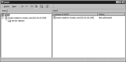
Figure 28.2. The MMC DHCP snap-in is used to manage the DHCP service on the Windows 2000 Server.
On the left side of the management console is a tree structure that can be used to manage one or more DHCP servers from a central location. Click on the server that falls under DHCP and you’ll see the Server Options folder for this particular DHCP server.
After you click on the server, you’ll notice that the icon to the left of the server name will change and a red arrow (pointing downward) will appear on top of the icon. This is a reminder that this server has not yet been authorized in the Active Directory. Windows 2000/2003 DHCP servers perform a process called rogue server detection. When a Windows 2000/2003 server boots and the DHCP service is started, it sends out a DHCPINFORM packet. Other DHCP servers, if any are configured on the network, reply with the DHCPACK message. Next, the service checks to see whether it is registered in the Active Directory. If it is not, it will not begin answering client requests. Figure 28.3 shows an example of the event log entry that the server makes when this occurs.
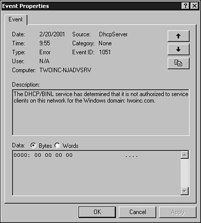
Figure 28.3. The DHCP server will log an error in the system event log file if it is not authorized to run on your network.
The DHCP server undergoes this rogue server detection process once each hour. Thus, each DHCP server can keep track of other authorized DHCP servers on the network.
Authorizing a server is simple:
1. Log on to the server using an administrator-level account.
2. Run the DHCP MMC snap-in by selecting it from the Administrative Tools folder.
3. Click once on the server you want to administer.
4. From the Action menu, select Authorize. It might take up to a minute or two before the process completes.
Use the Refresh option from the Action menu to determine when the process has finished. The red arrow is replaced with a green arrow pointing upward.
Using the MMC Action Menu
To configure a server, click once to highlight it, and then click the Action menu. The Action menu allows you to perform the following tasks if you select a particular DHCP server object:
![]() Display Statistics—This shows statistical information about the selected server, such as the time the server started, the number of requests and offers, and the number (and percentage) of addresses in use, among other things.
Display Statistics—This shows statistical information about the selected server, such as the time the server started, the number of requests and offers, and the number (and percentage) of addresses in use, among other things.
![]() New Scope—Use this to create a new scope of IP addresses that the server can offer to clients. After the server is authorized in the Active Directory, this will be the first action you take to set up an address space the DHCP server can use.
New Scope—Use this to create a new scope of IP addresses that the server can offer to clients. After the server is authorized in the Active Directory, this will be the first action you take to set up an address space the DHCP server can use.
![]() New Multicast Scope—Use this to set up a group of IP multicast addresses that can be distributed to computers on the network. You can use this to define multicast scopes for selected network computers.
New Multicast Scope—Use this to set up a group of IP multicast addresses that can be distributed to computers on the network. You can use this to define multicast scopes for selected network computers.
![]() Reconcile All Scopes—This menu option compares information in the DHCP database about address scopes with that stored in the Registry and reconciles any differences. Although it’s not a substitute for better disaster recovery operations (such as making backups), this can be used to recover a DHCP server and be sure that the scope of addresses it is allowed to use is valid.
Reconcile All Scopes—This menu option compares information in the DHCP database about address scopes with that stored in the Registry and reconciles any differences. Although it’s not a substitute for better disaster recovery operations (such as making backups), this can be used to recover a DHCP server and be sure that the scope of addresses it is allowed to use is valid.
![]() Authorize/Unauthorize—As explained in the preceding section, this action item allows you to authorize a server to function on the network by registering it in the Active Directory. This option is presented as Unauthorize if you’ve highlighted a server that is already authorized.
Authorize/Unauthorize—As explained in the preceding section, this action item allows you to authorize a server to function on the network by registering it in the Active Directory. This option is presented as Unauthorize if you’ve highlighted a server that is already authorized.
![]() Define User Classes—Use this to create classes of options. Clients can be assigned to a class to gain access to options not defined by their scope.
Define User Classes—Use this to create classes of options. Clients can be assigned to a class to gain access to options not defined by their scope.
![]() Define Vendor Classes—This option enables you to create vendor-specific option classes.
Define Vendor Classes—This option enables you to create vendor-specific option classes.
![]() Set Predefined Options—This enables you to set up predefined option classes. These include DHCP standard options (as defined in the RFCs), Microsoft options, Microsoft Windows 2000 options, and Microsoft Windows 98 options.
Set Predefined Options—This enables you to set up predefined option classes. These include DHCP standard options (as defined in the RFCs), Microsoft options, Microsoft Windows 2000 options, and Microsoft Windows 98 options.
![]() All Tasks—This gives you access to the Stop/Start/Pause/Resume/Restart tasks.
All Tasks—This gives you access to the Stop/Start/Pause/Resume/Restart tasks.
![]() Delete—This menu option deletes the selected entry in the MMC console tree.
Delete—This menu option deletes the selected entry in the MMC console tree.
![]() Refresh—This refreshes the current display.
Refresh—This refreshes the current display.
![]() Properties—This option brings up the properties page for the selected entry.
Properties—This option brings up the properties page for the selected entry.
When you first install the service, the first thing you need to do is create a scope of IP addresses that the DHCP server can use to allocate leases to its clients. After that, other options in the Action menu can be used to further configure the server.
Creating an Address Scope
After you have authorized a server on the network, you can create a scope of addresses that the DHCP server can administer to clients. From the MMC utility, click once on the server you want to administer, and then select New Scope from the Action menu. The New Scope Wizard pops up. Alternatively, you can right-click the server and select New Scope. Click Next to dismiss the introductory dialog box and continue creating an address scope. The wizard then prompts you through the following steps:
1. A dialog box pops up that you can use to give the scope a name and description. The description is optional, but you must at least supply a name for the scope so that it can be differentiated from other scopes you might create. Enter the name and, if you want, a description and click Next.
2. The next dialog box, shown in Figure 28.4, prompts you to enter the range of IP addresses for this scope. Enter a starting address and an ending address. You also should enter a subnet mask associated with this address range. The subnet mask can be entered in the traditional way using dotted-decimal notation, or you can specify the mask by indicating the number of bits in the Length field (as in CIDR notation). When finished, click Next.
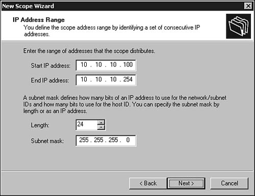
Figure 28.4. The wizard prompts you to enter the address range and specify the subnet mask for the scope.
3. The next dialog box (shown in Figure 28.5) enables you to specify any addresses that fall within the range you have entered that you want to exclude from the scope. You can enter a single address and click the Add button, or you can enter a range of addresses (starting and ending addresses) and click the Add button. If you change your mind about an address, highlight it and click the Remove button. When finished adding addresses to be excluded, click Next. You should exclude the DHCP server’s own address if it falls within the range of addresses you defined in the preceding step.
4. Next, you are prompted to enter the amount of time to lease the addresses in this scope. This dialog box defaults to 8 days. As it suggests, you should consider creating scopes that have lease values relevant to your network. For example, mobile computers that frequently move from one place to another can be given a shorter lease time, thus keeping your address pool from becoming populated by unexpired, unused leases. This dialog box also enables you to specify the lease in hours, minutes, and seconds.

Figure 28.5. Enter the address range to be excluded from use by the DHCP server and an appropriate subnet mask for the address range.
5. As discussed earlier in this chapter, the DHCP packet can contain various options. The dialog box asks if you want to enter options valid for this scope or to put it off until another time. For this example, go ahead and configure the options. Leave the Yes, I Want to Configure These Options Now radio button selected, and click Next.
6. The first option, shown in Figure 28.6, prompts you to enter the default gateway for the subnet covered by this range of addresses. Enter one or more IP addresses for the routers you want to use, clicking the Add button to add each one. Note that here you are entering the default gateway to which clients will send IP datagrams when the destination is not on the local subnet. This is not the gateway computer discussed earlier in this chapter that serves as a BOOTP or DHCP Relay Agent. Again, if you change your mind, you can highlight any router address and click the Remove button to delete it from this list. Click Next when you have finished adding routers.
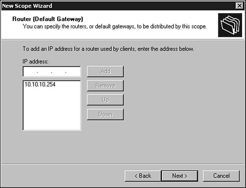
Figure 28.6. Enter one or more routers that will operate as default gateways for the LAN segment served by this scope of IP addresses.
7. Next, a dialog box prompts you to enter the parent name of your network. This is the name of the domain that client computers are configured to use for DNS name resolution. In Figure 28.7 you can see that you can also enter the names or addresses of domain name servers the client is configured to use. If you enter a server name, click Resolve to have the wizard look up the address, or enter an address and click Add to add it to the list. Use the Remove button if you change your mind. Place the order of DNS servers in the same order in which you want clients to access them. You can highlight a server in the list and use the Up and Down buttons to change the order.
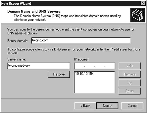
Figure 28.7. Enter the client computer’s domain name and then the domain name servers for the domain.
8. If you are still using Microsoft’s Windows Internet Naming Service (WINS), you can use the next dialog box, shown in Figure 28.8, to enter the names or addresses of the WINS servers. If you enter the name, use the Resolve button again to have the server translate the WINS server’s name to an IP address.
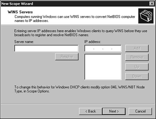
Figure 28.8. Enter the name or IP address of each WINS server that clients can use.
9. Finally, a dialog box asks whether you want to activate the scope now or later. The server does not begin allocating addresses in the scope to clients until the scope is activated. After making your choice, click Next.
10. A final dialog box notifies you that the wizard is finished creating the scope. Click the Finish button.
If you did not choose to activate the scope, you can do so later by right-clicking on the scope and selecting Activate. Alternatively, click once on the scope and select Activate from the Action menu.
In Figure 28.9 you can see the DHCP MMC snap-in after a scope has been created and activated.
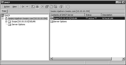
Figure 28.9. The new scope shows up in the right pane of the DHCP MMC snap-in utility.
The Status field in this display tells you whether the scope is active, and the Description field can be useful when you create multiple scopes and need a reminder of their use. After the scope has been activated, clients that boot on the network and that have been configured to use a DHCP server can now receive configuration information from this DHCP server. If you expand the scope by clicking on the plus sign in the left pane, you can see that there are four other objects that can be managed. Figure 28.10 shows the new scope with the Address Pool object selected.
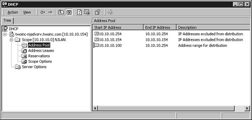
Figure 28.10. You can manage addresses, leases, reservations, and options offered by the scope using the DHCP MMC snap-in.
You can click on any of the other objects to see information. For example, if you want to see what options are enabled in this scope, click Scope Options. The option number (from the RFCs), name, and values for the options are displayed. In the case of this initial setup using the wizard, you would see options for the default router (gateway), DNS server, and domain name. If you entered an address for a WINS server, that option would also be displayed.
Reserving a Client Address
You can choose to exclude certain addresses from a scope that you know are configured manually, such as routers. However, you might want to use the Reservation method to reserve an address for a DHCP client that might need to keep the same IP address, but obtain other information from the DHCP server at times. A DNS server is a good example of a server that should have a reserved address.
To reserve an address within a scope, expand the scope in the MMC console and open up the Reservation dialog box either by highlighting the Reservation object and selecting New Reservation from the Action menu, or by right-clicking the Reservations object and making the same selection. In Figure 28.11 you can see the simple dialog box used to create a reservation.
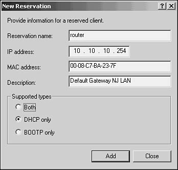
Figure 28.11. You can identify specific computers that will have a reserved IP address on the DHCP server.
As discussed later in this chapter, assigning options to a reserved IP address gives the administrator the best method for fine-tuning what options the client will end up being offered by the DHCP server. Options associated with a reservation override all other options defined for the server, the scope, or any option class to which the computer might belong.
Configuring the DHCP Server and Scope Options
Earlier in this chapter, many options that can be used for BOOTP and DHCP clients were discussed. The Windows 2000/2003 DHCP service enables you to configure which options will be offered to clients of the service. To configure the options, expand the MMC tree of DHCP servers to locate the server you want to manage. Click that server to get to the Options Folder for that server. After you have highlighted the Options Folder, click the Action menu.
Note
Although the RFCs support option overloading, as described earlier in this chapter, note that the Microsoft DHCP server does not support this function. Additionally, the maximum number of bytes stored in the DHCP packet options field is 312 bytes.
From the Action menu, select Configure Options. In Figure 28.12, you can see the default dialog box used for configuring options. Note that this dialog box has a General and an Advanced tab. Figure 28.13 shows the Advanced tab.
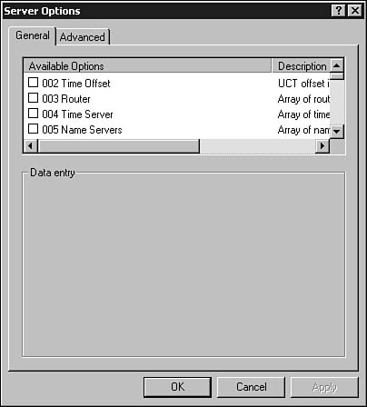
Figure 28.12. You can configure the options that the server can present to clients using this dialog box.
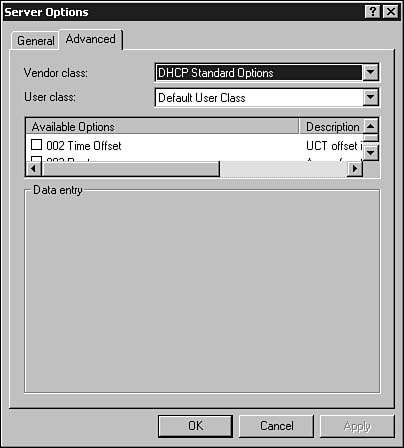
Figure 28.13. The Advanced tab enables you to more precisely control the options that are offered to clients.
Because the server enables you to specify options for several levels, it is important to understand the precedence used to decide which options apply to a client. Options can be set for the following, and in this order:
![]() Global Options—These are the server’s global options. These options apply to all scopes, unless superceded by the following options.
Global Options—These are the server’s global options. These options apply to all scopes, unless superceded by the following options.
![]() Scope Options—These apply to a scope the client uses. Options in this class that conflict with server global options will supercede them.
Scope Options—These apply to a scope the client uses. Options in this class that conflict with server global options will supercede them.
![]() Class Options—These apply to clients that are members of the class. Options in a class will supercede server global options and class options.
Class Options—These apply to clients that are members of the class. Options in a class will supercede server global options and class options.
![]() Reserved Client Options—By assigning options to a particular client for which an IP address reservation has been created, you are given the finest granularity of control. Options defined for a reserved client address override all other options.
Reserved Client Options—By assigning options to a particular client for which an IP address reservation has been created, you are given the finest granularity of control. Options defined for a reserved client address override all other options.
Similarly, you can configure options for a scope if you did not do so during the initial creation of the scope. You also can use these same steps to change or add options to the scope. To change the options for a scope, expand the scope and select the Scope Options folder.
Option Classes
In Figure 28.12, the list of Available Options is the list of options that are defined for the current DHCP server, and they are mostly the same options you’ll find in RFC 2132. Note that although the server can offer all these options, not all Microsoft clients can use this entire set of options, which is why the wizard prompted you for only a few options when it allowed you to select options for the newly created scope.
The Advanced tab shown previously in Figure 28.13 enables you to look at the different classes of objects. You’ll see a vendor class and a user class. Vendor classes are groupings of options that are useful for a particular vendor’s client, such as Microsoft 98 or Windows NT clients. User classes are for grouping options that a particular class of users has in common; for example, BOOTP clients or Remote Access users.
If you define options for the server, the scopes you create will inherit them. A good place to start is to define the basic subset of options that all clients will need, if you have such a list, and configure these options for the server. Next, you can expand the particular scope and select the Scope Options folder to add or remove options that apply to a particular scope.
Superscopes
In the earlier example, only one scope of addresses was created on the DHCP server. The server is capable of handling additional address scopes, however, to provide for other clients that might be physically accessible to the DHCP server but use a different logical subnet address. To create a supers-cope, you first must create the scopes to be included in it. Use the same procedures as before to create the new scope, specifying its address range, options, and so on. Next, select New Superscope from the Action menu. A wizard pops up and again prompts you through the process:
1. Click the Next button to dismiss the wizard’s opening dialog box.
2. In the next dialog box, give your superscope a name and click Next.
3. Figure 28.14 displays the current list of scopes defined on the server. Select the scopes that will fall under this superscope. Use Shift+click and Ctrl+click to select one or more scopes from the list. Click Next.
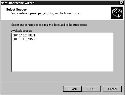
Figure 28.14. Select the scopes to include in the superscope.
4. Finally, the wizard shows you a summary of your superscope, including the name and the names of the scopes that make it up (see Figure 28.15). Click the Finish button.
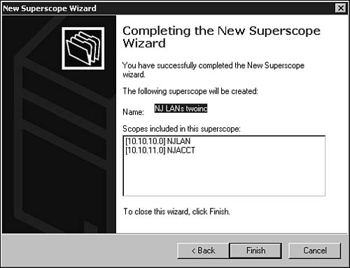
Figure 28.15. Confirm your selections before exiting the Superscope Wizard.
Providing Support for BOOTP Clients
The Windows 2000/2003 DHCP servers provide support for BOOTP clients. The Default BOOTP user class of options is used to configure the information that is supplied to these clients. Although standard BOOTP servers require that the server be configured in advance with a table of client hardware addresses and corresponding IP addresses, Windows 2000/Server 2003 DHCP servers instead select the next available address to give to a BOOTP client. This matches the method the DHCP server uses when granting IP address leases to its DHCP clients.
Enabling the DHCP Relay Agent
RFC 1542, “Clarifications and Extensions for the Bootstrap Protocol,” defined support for a BOOTP relay agent. That agent now is supported by almost every router. The relay agent function enables you to support clients on different subnets using a single BOOTP or DHCP server. DHCP requests are forwarded by the router to the DHCP server, and the server’s responses are returned to the client. Because BOOTP and DHCP use almost the same frame format and the same UDP ports, you’ll also find that most BOOTP relay agents will perform this duty for DHCP clients.
However, on a small network, you might not have a router. Instead, you might be using the Routing and Remote Access services available in Windows 2000/2003 Servers. In that case, you’ll need to add the DHCP Relay Agent protocol. Follow these steps to enable the DHCP Relay Agent:
1. Click Start, Programs, Administrative Tools (Start, Administrative Tools for 2003), and then Routing and Remote Access (for Windows Server 2003, Start, Administrative Tools, Routing and Remote Access).
2. In the left pane of the MMC console utility, click the plus sign to expand the server’s list of objects.
3. Click the plus sign for IP Routing to expand the list of objects it contains.
4. Right-click on General, and from the menu that pops up select New Routing Protocol.
5. In Figure 28.16, you can see the New Routing Protocol dialog box displaying a list of available protocols. Select DHCP Relay Agent, and click OK to dismiss the dialog box. The DHCP Relay Agent protocol now shows up as an object under IP Routing.
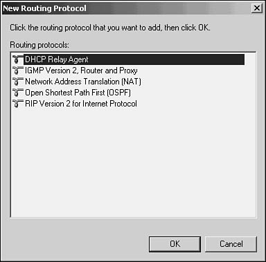
Figure 28.16. The New Routing Protocol dialog box enables you to install the DHCP Relay Agent service.
6. Right-click on this new object and select Properties. In the Properties sheet for the DHCP Relay Agent, you can add the addresses of one or more DHCP servers to which BOOTP and DHCP messages will be relayed (see Figure 28.17).
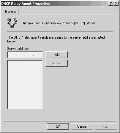
Figure 28.17. The Properties sheet for the DHCP Relay Agent is where you specify the DHCP servers that will handle requests forwarded by the relay service.
When the relay agent receives a DHCP or BOOTP broadcast message on one of its network interfaces, which it can recognize because the packet is addressed to port 67, it will forward the message to a DHCP server. You can see an example of this in Figure 28.18. The DHCP server resides on Subnet 1 along with other servers. This subnet is connected to Subnet 2 using a router—or possibly a Windows 2000 server running the DHCP Relay Agent service.
Figure 28.18. The DHCP Relay Agent can support clients on another subnet.
When Workstation A on Subnet 2 boots, it broadcasts a DHCPDISCOVER message using UDP. When the router sees this broadcast, it looks at the Gateway Address field (discussed earlier in this chapter, and not to be confused with a default gateway on a TCP/IP LAN). If the value for this field is all zeros (0.0.0.0), the relay agent service on the router will place its own address in this field. This enables the DHCP server to reply directly to the router when it replies to the DHCP or BOOTP request.
The DHCP server looks at the Gateway Address field. It then consults its list of scopes to determine an appropriate address based on the value of the Gateway Address field and sends a DHCPOFFER packet back to the router, which then broadcasts the packet on Subnet 2. Remember that a broadcast is necessary in this case because at this time Workstation A knows its hardware address but doesn’t yet have an IP address. If the client decides to accept the address offer, it sends a DHCPREQUEST message to the server and the server responds with a DHCPACK acknowledgment granting the workstation the lease.
What Is a DHCP Cluster?
If you are using Windows 2000 Advanced Server or Windows Server 2003 Enterprise or Datacenter servers, you can use the clustering feature for DHCP. This allows two separate DHCP servers to be administered as a single DHCP server. Windows 2000/2003 clustering supports a failover mode in which a service running on one computer can be monitored. If the node that is supplying a DHCP service supported by the clustering software fails, another node that runs the same service can be activated to take over for the failed node. By clustering DHCP services between two nodes, you will make the network less prone to downtime due to problems with your DHCP server.
The alternative to clustering is to use two separate DHCP servers, each responsible for a portion of the address scope. This allows all your clients to get an address from one or the other server. Because leases are usually measured in days or weeks on a stable network, the loss of a single DHCP server for a few hours or a day or so might not cause you any problems unless someone decides to reboot every PC on the network. A secondary server configured with a smaller portion of the address space can continue to handle DHCP traffic while the main server is repaired.
In a larger network, however, where computers are frequently moved, a more stable DHCP service can be provided by hosting the DHCP service on a cluster.
Keep the following points in mind when using a Windows cluster for the DHCP service:
![]() The DHCP service should be installed before the clustering service is installed on the computers.
The DHCP service should be installed before the clustering service is installed on the computers.
![]() As with most cluster installs, one server should be configured first, with the DHCP service and the clustering service, while the other cluster member-to-be is powered off.
As with most cluster installs, one server should be configured first, with the DHCP service and the clustering service, while the other cluster member-to-be is powered off.
![]() When you’re finished with the installation on the first member, power up the second and install the DHCP service and then the cluster service.
When you’re finished with the installation on the first member, power up the second and install the DHCP service and then the cluster service.
In addition, keep in mind that the cluster itself must have a unique IP address, which can’t be delegated to it by a DHCP server. Additionally, you’ll need to create a domain security group and make both servers members. To this group, assign Full Control permissions for the DNS zone object in the Active Directory where DHCP A and PTR records are stored for the servers’ clients.
Using Windows clusters is the subject of many books. Before you decide to use a cluster on your network, I would recommend that you become intimately familiar with Windows clusters. There are many aspects of clustering (such as the utilities used to start/stop and otherwise manage the cluster) that you need to learn before you try to set DHCP and the clustering software.
Considerations for Using DHCP in Large or Routed Environments
In a large network you need to provide for redundancy for DHCP servers. Because a larger network is typically connected using routes to join a diverse set of network segments, you will need to enable BOOTP and DHCP forwarding on any routers in the network. Each DHCP server will need to be carefully planned, and the address scopes, reservations, and exclusions will need to be carefully thought through in advance. You don’t want, for example, a DHCP server to allocate an address to a client when that address should have been reserved and already is in use by another server! This is exactly the kind of thing automatic dispensing of IP addresses is supposed to solve.
Of course, when you’re planning the placement of DHCP servers in a large, routed environment, it’s easiest to place a single DHCP server on each subnet. In many cases, though, this is not practical. And with the forwarding capabilities it is not necessarily needed. Also, don’t yield to the temptation of placing all your DHCP servers on the same subnet, allowing them to receive forwarded replies from other network segments. If the single subnet becomes unavailable, all your DHCP servers become unavailable. This applies to any major server. Don’t place all your eggs in one basket, so to speak.
How DHCP Interacts with Microsoft’s Dynamic Domain Name Service (DNS)
Microsoft’s version of DNS supports dynamic updates, as specified in RFC 2136, “Dynamic Updates in the Domain Name System (DNS UPDATE).” Windows 2000 clients can send dynamic updates after having received configuration information from a DHCP server. When a DHCP lease expires, the client will send an update to deregister the addressing information.
To register with DNS, the client first contacts a name server. If the name server is just a local server and is not authoritative for the zone, it will return the address of the authoritative server to the client. The client then will contact the primary authoritative server to send it the updated addressing information. If it’s successful, a reply is sent back to the client.
The DHCP server also can be used to send dynamic updates to DNS. This is useful for pre-Windows 2000 clients that do not understand the dynamic update process. This also can be negotiated between the DHCP server and a Windows 2000 client during the initial DHCP process. This is done using a special FQDN (fully qualified domain name) DHCPREQUEST packet (using Option number 81). This packet has three possible flags that can be set:
![]() 0—This flag specifies that the client wants to be responsible for updating the A resource record on the DNS server, but would like for the DHCP server to update the PTR resource record.
0—This flag specifies that the client wants to be responsible for updating the A resource record on the DNS server, but would like for the DHCP server to update the PTR resource record.
![]() 1—This flag specifies that the client wants to perform both updates.
1—This flag specifies that the client wants to perform both updates.
![]() 3—If this flag is set, the DHCP server will register both records, regardless of the client’s wishes. If the server sends a packet to the client with this flag set, the client does not attempt any updates.
3—If this flag is set, the DHCP server will register both records, regardless of the client’s wishes. If the server sends a packet to the client with this flag set, the client does not attempt any updates.
![]() For more information about A and PTR records that are used in the DNS database, see Chapter 29.
For more information about A and PTR records that are used in the DNS database, see Chapter 29.
These flags are not all that controls the process of which computer performs which updates. Instead, both the client and the server can be configured to perform (or not perform) this function.
Configuring Dynamic Updates on the DHCP Server
On the server side, you can specify in the properties page for the server how it will respond to dynamic update requests, and whether it will perform dynamic updates for clients that do not support this function (that is, pre-Windows 2000 clients). To configure the service for this functionality, follow these steps:
1. Click Start, Programs, Administrative Tools, DHCP (or Start, Administrative Tools, DHCP for Windows Server 2003).
2. In the left pane, expand the tree structure by clicking the plus sign next to the server’s name to expand the tree to show the scopes that belong to the server.
3. Right-click the scope you want to modify, and select Properties.
4. When the Properties page appears, click the DNS tab. In Figure 28.19 you can see the properties found on this tab.
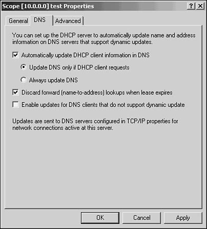
Figure 28.19. The DNS tab enables you to configure DHCP server behavior in regard to DNS dynamic updates.
5. The first check box, Automatically Update DHCP Client Information in DNS, enables you to specify this function using two options. Click either the Update DNS Only If DHCP Client Requests radio button or the Always Update DNS radio button. If you select the second button, the server will always make updates for clients, ignoring their requests.
6. To enable the server to handle dynamic updates for clients that do not support dynamic DNS update, select the check box Enable Updates for DNS Clients That Do Not Support Dynamic Update.
7. Click the Apply button, and then click the OK button to dismiss the dialog box.
Configuring Dynamic Updates on the Client
You also can control how the client handles the dynamic DNS update function if you are using Windows 2000 clients. Remember from the preceding section that the server can override a client’s request if the appropriate selection is made on the scope’s DNS properties page.
Windows 2000 clients and servers, as well as Windows XP and Windows Server 2003, are already configured, by default, to send the FQDN packet with the Flags field set to zero. This means the client wants to update the A resource record and wants the server to update the PTR record. You can change this behavior by doing the following:
1. Right-click the My Network Places icon (or double-click the Network icon in the Control Panel). For Windows Server 2003, click on Start, Control Panel, Network Connections.
2. Right-click the icon for the network connection you want to configure. From the menu that pops up, select Properties.
3. Highlight Internet Protocol (TCP/IP) and click the Properties button.
4. Click the Advanced button, and then select the DNS tab. A properties page similar to that shown in Figure 28.20 pops up. At the bottom of the properties page, you’ll notice that Register This Connection’s Addresses in DNS is selected, and Use This Connection’s DNS Suffix in DNS Registration is not. The second option is the default.
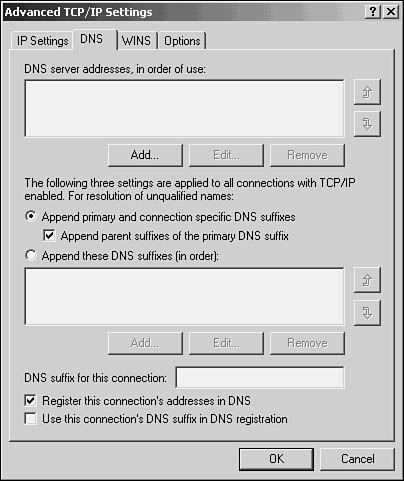
Figure 28.20. You can control the client’s capability to dynamically update DNS from this properties page.
5. To disable the client from performing DNS updates, deselect the check box labeled Register This Connection’s Addresses in DNS.
6. When finished, dismiss the properties page by clicking OK in each dialog box.
Reservations and Exclusions
Some computers or other networked devices, such as routers or printers, might need to keep the same IP address all the time. For example, Microsoft very strongly suggests you be sure that your DHCP server has a static, unchanging address. There are two ways you can be sure a particular computer or device keeps the same static address. The first method is to manually configure the client using the client’s software. For example, when you configure a Microsoft Windows 2000 Professional client or a Windows XP client, you can specify a static IP address (along with other network information) using the TCP/IP properties page for the client.
If you use the first method, you’ll need to exclude the address you use from the address pool that you assign to a scope. If you forget this step and the address does fall within the range of a scope, eventually it will be issued to a client, causing a duplicate address error on the LAN.
A reservation is similar to an exclusion but is used for computers or devices that do support DHCP but still require a constant, static address. You can enter a reservation for an address that falls within the address pool for a scope. The reservation is linked to the computer or device’s hardware address so that when it boots and begins the process of obtaining configuration information via DHCP, it will always receive the same address.
Exclusions are created when you create the address pool as explained earlier in this chapter. To create a reservation, carry out these steps:
1. Bring up the DHCP MMC console by clicking Start, Programs, Administrative Tools, DHCP. Expand the tree in the left pane to get to the scope in which the reservation will be created.
2. Expand the scope and right-click Reservations.
3. From the menu that pops up, select New Reservation.
4. The New Reservation dialog box appears. Enter a descriptive name you want to use for this reservation.
5. Next, enter the IP address that falls within the scope but that is to be reserved.
6. Enter the hardware address of the computer for which this address will be reserved. For Windows NT/2000 clients, use the ipconfig /all command at the command prompt to get this address. For routers or other computers, consult your documentation.
7. Select whether the reservation will be used for a BOOTP request, a DHCP request, or both.
8. Click OK to dismiss the dialog box. The reservation is complete. The address is handed out only to the device that uses the hardware address (also called the MAC address) you defined for the reservation.
Note in this example the reservation was made for a router. Other types of devices for which you might want to reserve addresses (or exclude if the computers are statically configured) are important servers that are mapped to specific addresses in your DNS system. Also, if you have non-Windows clients, such as Linux or Unix desktops or servers, you might want to reserve an address for them if they cannot use DHCP.
What Is APIPA?
If a client is configured to use DHCP, what happens if no DHCP server is available on the network? Starting with Windows 98, Microsoft Windows clients can use Automatic Private IP Addressing (APIPA). This is not a solution for a large network. It is for use on small LANs, such as a home office with 25 or fewer network nodes.
Simply configure each client computer to use DHCP in the properties page for TCP/IP, and reboot. When the client computer realizes that no DHCP server is on the network (because it’s not receiving any replies from its broadcasts), it will timeout and begin to use APIPA. The scheme in which addresses are allocated is not that complicated.
The network of addresses reserved for use by APIPA is 169.254.0.1 to 169.254.255.254, with a subnet mask of 255.255.0.0. When the client does not receive an answer from any DHCP server after a short time, it will select an address randomly from this network. It then will test to see whether this address is already in use.
Note
The only information that APIPA will configure for the client computer is an IP address and a subnet mask. It does not allow the client to configure other items that could be offered as options by a DHCP server. One important item to note is that APIPA does not provide the capability for the client computer to detect a default gateway. Thus, communication is limited to computers on the local LAN that all share the same 169.254.0.0 network address space. If you plan to connect your small LAN to the Internet, or to any other network using a router, you’ll need to either manually configure IP addressing information on each client or configure a DHCP server that can perform this function for you.
Note that a Microsoft client that is using APIPA will periodically check the network (about every five minutes) to see whether a DHCP server has become available. If one does come online, the client will perform as any other DHCP client and obtain configuration information from the DHCP server it discovers. Some older versions of Windows, notably Windows 98, do not automatically check for DHCP servers. In such cases, after you solve the problem that caused the computer not to find the DHCP server (such as a loose or damaged network cable), restart the computer. The computer should receive a valid IP address from the DHCP server after rebooting.
Because clients randomly choose IP addresses, it is always quite possible that one computer will choose an address already in use. To solve this problem, each computer first chooses an address and then broadcasts a packet containing that IP address and waits to see whether another computer replies that the address is already in use. This is referred to as gratuitous ARP. When this occurs, a client will attempt to select an IP address up to 10 times before ending the process.
Tip
If a Windows 2000 or Windows XP client is unable to receive a valid IP address from a DHCP server, but other devices connected to the same DHCP server are working correctly, check physical connections to the network and restart the connection and then the computer. If you are still unable to make a connection, make sure the malfunctioning client’s DHCP client service is running.
To check the status of a computer’s DHCP client service, follow these steps:
1. Right-click My Computer and select Manage.
2. Click Services and Applications, Services.
3. Scroll down to DHCP Client. Make sure the status is listed as Started and the startup type is Automatic.
4. To start the service or change the startup type, double-click DHCP Client. Click Start to start the client and select Automatic as the startup type.
5. Click Apply, and then OK.
Creating a Manual IP Address As an Alternative to APIPA
APIPA can be useful in creating a small LAN that does not need access to the Internet or another network. It can also be confusing, however, if your computers can connect to each other but not the Internet. As an alternative to using APIPA, you can assign an alternate manual IP address to computers running Windows 2000 or Windows XP. The alternate address is used if the computer is unable to connect to a DHCP server. Follow this procedure:
1. Open the properties sheet for the current network connection.
2. Click the General tab.
3. Select Internet Protocol (TCP/IP) and click Properties.
4. Click the Alternate Configuration tab. Select User Configured.
5. Enter the IP address, subnet mask, default gateway, and DNS and WINS server information for the network client. Note that the IP address must be unique for each client, but the other information is the same for each user on the network. To obtain this information, use ipconfig /all as discussed in Chapter 27, “Troubleshooting Tools for TCP/IP Networks.”
6. Click OK when finished.
If the client is unable to connect to a DHCP server, it uses the alternate manual address instead. This can keep your network running if the DHCP server fails but a different device or server is responsible for routing traffic to other networks or the Internet.
Troubleshooting Microsoft DHCP
Troubleshooting DHCP can be a complicated process. Perhaps you’ve forgotten to authorize the server on the network or activate a scope. Clients might be unable to locate the server. In any case, there are several things you can do to troubleshoot DHCP problems. With the client, start by using the ipconfig /all command at the command prompt to view IP configuration data. If the client shows either no address or an address of 0.0.0.0, a problem exists between the client and the server. It might be a network card, a misconfigured router, or another network component. Use the standard TCP/IP tools (that is, ping or tracert) from another client on the same subnet to the DHCP server to see whether connectivity exists. If you can’t reach the DHCP server from that client, try the same tests from other clients on other subnets to help localize where in the network the problem lies.
Two other useful tools for troubleshooting are the Windows 2000 and Windows Server 2003 Event Logs and the DHCP server’s own audit log file. Earlier in this chapter you saw an example of an event log entry. In the next section you’ll learn how to enable the DHCP server’s own logging capabilities.
Managing Logging
Besides the records that the DHCP server records in the event log, you also can enable logging by the server to its own log file. For troubleshooting purposes, both the event log and the server’s own log file can be very useful.
To manage the server’s log file, follow these steps:
1. Start the DHCP MMC console.
2. Click once on the server you want to modify, and select Properties from the Action menu. Alternatively, right-click on the server and select Properties.
3. In the General tab for the properties page for the server select the check box labeled Enable DHCP Audit Logging.
4. Click the Advanced tab. Here you will find two fields. You can use the first field to enter the location where you want the log files to be created. The default is %systemroot%System32dhcp.
5. The second field can be used to enter the path for the location of the DHCP database files. The default for this is the same as that for the log files.
6. Click OK to dismiss the properties page when you have finished viewing or modifying these fields.
When you enable audit logging, a new log file is created at midnight each day. Header information is written to the file and significant events are logged. The format for the filename used for log files is DhcpSrvLog.day of week. For example, a log file created on Monday morning would be named DhcpSrvLog.Mon.
Because the day of the week is used as the file extension for the log file, it should be obvious that in a week you’ll have to overwrite an existing file. Indeed, this is what happens unless the file has been modified within the past 24 hours. If this happens, logging will be suspended until the file is removed or renamed.
The log file is a simple ASCII text file using comma-delimited fields. Each event is recorded as a single line in the file, using the fields
ID, Date, Time, Description, IP Address, Host Name, MAC Address
which are as described here:
![]()
ID—An event code to indicate the kind of event logged.
![]()
Date—The date of the event.
![]()
Time—The time of the event.
![]()
Description—A short description of the event.
![]()
IP Address—The IP address of the client.
![]()
Host Name—The hostname of the client.
![]()
MAC Address—The hardware (MAC) address of the client.
The standard event IDs are as listed here:
![]() 00—The log was started.
00—The log was started.
![]() 01—The log was stopped.
01—The log was stopped.
![]() 02—Because of a low-disk-space condition, logging was suspended.
02—Because of a low-disk-space condition, logging was suspended.
![]() 10—A new IP address lease was granted to a client.
10—A new IP address lease was granted to a client.
![]() 11—A client renewed its lease.
11—A client renewed its lease.
![]() 12—A client released its lease.
12—A client released its lease.
![]() 13—An address was found to be already in use on the network.
13—An address was found to be already in use on the network.
![]() 14—The address pool has been completely used, so the server was unable to grant a lease to a client.
14—The address pool has been completely used, so the server was unable to grant a lease to a client.
![]() 15—A lease was denied to a client.
15—A lease was denied to a client.
![]() 20—An address was given to a BOOTP client.
20—An address was given to a BOOTP client.
As you can see, a significant amount of information is stored in the log files. Start your troubleshooting efforts here if you are experiencing problems with the server itself or with multiple clients. You can follow the trail of events leading up to the current problem. Again, if you are having problems with a single client, examine the event log file on the client to look for any indication that the client was unable to locate or interact with the DHCP server.
Using DHCP with Red Hat Linux
During the installation of Red Hat Linux, you will be prompted for the network components to install, just as you are with Windows. You can specify at that time to use DHCP for a client workstation, or you can assign a static address. If you elect to use DHCP, you will be able to access a DHCP server to obtain IP configuration information from a DHCP server. You can also choose to install a DHCP server when you install Linux so that you can service other client computers.
The client configuration information is stored in several files for Red Hat Linux:
![]()
dhclient.conf—This file stores information about all network devices attached to the computer, such as the amount of time the client will wait before attempting to contact a DHCP server when no response has been received. If you have a DNS server that supports dynamic updates, you can list the fully qualified name of those servers in this file.
![]()
dhclient.leases—This file records leases previously obtained so that the client can request them again after a reboot. More than one address can be listed in this file because the computer can have more than one network interface.
![]()
dhcpd.options—This file lists options requested by the client, as described earlier in this chapter.
You probably won’t have to make any edits to the previously listed files—the default values created when you elect to use DHCP on the client are usually sufficient in all but the most extreme circumstances. If you do need to tweak some of the data contained in the configuration or options files, use the man pages for the DHCP client to obtain more detailed information.
The DHCP Server Daemon
The server portion of DHCP for a Red Hat Linux system is a background process (called a daemon) that is also started at boot time. The name of this daemon is dhcpd. Several important files used by the server daemon include the following:
![]()
dhcpd.conf—This is the configuration file for the daemon that contains, among other things, the range of IP addresses the server can lease to clients.
![]()
dhcpd.leases—The leases that have been allocated to clients are stored in this file. New leases are appended to the end of the file. Periodically, the server examines the file and removes addresses (or other information stored here) that is no longer valid, and rewrites the file so that it will be available if the server or the daemon is restarted. The old file is not deleted but instead is renamed dhcpd.leases~.
Although the actual command to start the DHCP server on the computer is contained in a startup file that is executed when the computer is booted, you can execute commands online to restart the server. This capability can be useful when you are debugging a problem with the server, for example, and want to run it as a foreground application instead of a background daemon.
The syntax for the DHCP daemon is
dhcpd [-p port] [-f] [-d] [-q] [-t | -T] [-cf configfile] [-lf leasefile] [-tf tracefile]
[-play tracefile] [if0 [... ifN]]
where
![]()
-p port—The standard port that the server listens to for DHCP requests is port 67. Use this to specify a different port number.
![]()
-f—Causes the server to be run as a foreground process instead of a background (daemon) process. This is useful when using a debugger to diagnose problems with the server.
![]()
-d—This option causes the server to output the DHCP log to the standard error descriptor instead of the syslog file.
![]()
-q—Suppresses printing the copyright notice when the daemon is started.
![]()
-t | -T—When the system is booted, the configuration file and lease file are read. The -t option will examine the configuration file to ensure that the syntax is correct, but won’t connect to the network. Similarly, the -T option will examine the lease database. When using the -play option (listed in the following text), use an alternate lease file because the playback option might overwrite your lease file with test data.
![]()
-cf configfile—Use this to specify a filename for the configuration file if you don’t want to use the default filename.
![]()
-lf leasefile—Use this to specify a filename for the lease file if you don’t want to use the default filename.
![]()
-tf tracefile—Use this to specify the filename that will log the startup of the server. Useful for debugging.
![]()
-play tracefile—Use this to “playback” the tracefile.
![]()
if0 [...ifN]—Specify the network interface on which the server will be used.
The DHCP Relay Agent
DHCP and BOOTP messages can be exchanged with clients and servers that are not on the same subnet. This is done by running the dhcrelay daemon on the subnet where the client resides. This daemon is responsible for intercepting the requests and forwarding them to a DHCP server and, likewise, returning the responses to the client.
The syntax for the agent can be found using the command man dhcrelay if you need to use this capability.
Configuring a Router or WAP to Provide DHCP Services
Many small- to medium-sized networks use the router that provides Internet access as a DHCP server, using it to provide network addresses to client PCs. Configuring a router to act as a DHCP server is not difficult (most routers are configured to provide IP addresses by default), but you should be familiar with the process so you can make changes to the configuration, and, most important in the case of a wireless access point (WAP) or wireless router, limit the number of IP addresses provided. By limiting the number of IP addresses to the number of clients on your network, you can help minimize the possibilities of unauthorized users borrowing your network for Internet access or hacking.
To view or change the configuration of your router’s DHCP settings, follow this basic procedure. This procedure is based on that used by Linksys routers, but others are generally similar:
1. Log into the router’s built-in configuration web server. Enter the router’s IP address (this is the IP address listed as “default gateway” by the ipconfig command or equivalent discussed in Chapter 27) and enter the username and password needed.
2. After logging into the router, open the DHCP configuration screen.
3. If no devices are able to get an IP address, make sure the DHCP server is enabled (see Figure 28.21). The DHCP server function should be disabled only if all clients have manually assigned IP addresses or if another device on the network is being used as a DHCP server.
Figure 28.21. Configuring a Linksys router to provide DHCP addresses to up to 10 clients.
4. Specify the starting IP address. Make sure the starting address is not already in use by a device with a manually assigned IP address.
5. Specify the number of DHCP clients. If you enter 10, as in Figure 28.21, the router provides addresses to up to 10 clients. You should adjust this number to reflect the maximum number of clients that might connect to this router. For example, if you have a mixed wired and wireless network with three wired clients and up to two wireless clients, make sure you specify 5 for the number. If you specify a number less than 5, one or more of the wireless clients will not receive an IP address when they connect. If you specify a number greater than 5 and don’t secure your wireless network, however, unauthorized clients might receive a DHCP address from your server and borrow your bandwidth or attempt to hack your network.
6. To determine what clients are currently using an IP address provided by this router, click the DHCP Clients button shown in Figure 28.21. On some routers, this information might be displayed on the same screen as the remainder of the DHCP information. Note that the computer (client) name and MAC (adapter physical) address are listed for each client (see Figure 28.22).
Figure 28.22. Displaying current clients connected to a Linksys router.
7. To refresh the listing shown in Figure 28.22, click Refresh.
8. If an unauthorized computer is listed when you display DHCP clients, click the box next to the computer’s MAC address and click Delete. This clears the connection from that computer to the router.
9. Close the dialog. Click Apply or OK to accept changes to the router configuration, or click Cancel to discard changes to the configuration. The router restarts and your changes to the router configuration are now operational.
Note that you need to have a list of authorized computer (client) names to determine which computers or devices are authorized when you view the list of active clients. You can generate this information by running the hostname command on each client PC.
![]() See “Using
See “Using hostname and Related Commands,” Chapter 27, p. 452, for details on running hostname.
For non-computer devices connecting to your network, check the device’s configuration; see the device’s documentation for details.
Using MAC Address Filtering to Stop Unauthorized Users
If your router lists unauthorized clients, use these methods to secure your network:
![]() Use the MAC filtering option available in most routers and APs. You can configure the router to permit only specified addresses to connect, or prevent specified addresses from connecting (see Figure 28.23). If you see the same unauthorized MAC address being listed repeatedly on the list of DHCP clients, you might want to use the option to block only specified MAC addresses and specify the offending address. It’s more secure, although more time-consuming, to permit only specified MAC addresses to connect. If you choose this option, make sure you have an up-to-date list of MAC addresses. If all authorized clients are currently connected, you can note the MAC addresses from the client listing shown in Figure 28.22. For clients not currently connected, you can use ipconfig /all (see Chapter 27) to display each client’s MAC address.
Use the MAC filtering option available in most routers and APs. You can configure the router to permit only specified addresses to connect, or prevent specified addresses from connecting (see Figure 28.23). If you see the same unauthorized MAC address being listed repeatedly on the list of DHCP clients, you might want to use the option to block only specified MAC addresses and specify the offending address. It’s more secure, although more time-consuming, to permit only specified MAC addresses to connect. If you choose this option, make sure you have an up-to-date list of MAC addresses. If all authorized clients are currently connected, you can note the MAC addresses from the client listing shown in Figure 28.22. For clients not currently connected, you can use ipconfig /all (see Chapter 27) to display each client’s MAC address.
Figure 28.23. Configuring MAC address filtering on a Linksys wireless access point.
If you use a router that supports both wired and wireless clients, you might need to specify the type of connection used for each MAC address you enter.
![]() On a wireless network, be sure to enable wireless security, preferably WPA or WPA2.
On a wireless network, be sure to enable wireless security, preferably WPA or WPA2.
![]() See Chapter 23, “Security and Other Wireless Technologies,” for details on enabling wireless security.
See Chapter 23, “Security and Other Wireless Technologies,” for details on enabling wireless security.
It’s far too easy now to add unauthorized users to an unsecured network. Whether by installing a small switch or a small wireless access point, it’s easy to break into a small network that relies on a DHCP-enabled router instead of a server with a list of authorized users. Use these methods to prevent unauthorized access.