CHAPTER 13. Ethernet: The Universal Standard
SOME OF THE MAIN TOPICS IN THIS CHAPTER ARE
A Short History of Ethernet 196
Collisions: What Are CSMA/CA and CSMA/CD? 199
Restrictions on Legacy Ethernet Topologies 203
Using a Backbone to Connect the Enterprise 208
Fast Ethernet (IEEE 802.3u) and Gigabit Ethernet (IEEE 802.3z) 213
If you sit down at almost any PC or desktop workstation today, it is very likely that the computer will be linked to the local network by one form of Ethernet or another. Although other local area networking (LAN) technologies, such as Token-Ring or Novell’s proprietary IPX/SPX, are still around, Ethernet-connected computers outnumber all other LAN technologies combined. You’ll also find that, most likely, Ethernet is the underlying networking technology that connects servers, printers, and other devices on your network. Ethernet has become so pervasive that every major manufacturer of networking equipment sells equipment that is designed to work with or provide interconnectivity with Ethernet LANs.
So before we start talking about network transport protocols, services, and applications, it is important that you get a good understanding of what Ethernet is and how it functions. It’s also important that you understand that there is more than one type of Ethernet. What started out as a simple LAN technology has evolved to the point that it is now seriously considered a wide area networking (WAN) technology. With technologies such as PPPOE, (Point-to-Point Protocol over Ethernet) which is a method for building PPP sessions and encapsulating packets, as described in RFC 2516 (http://www.ietf.org/rfc/rfc2516.txt), network providers of all types—DSL-based ISPs, for example—use Ethernet to provide connectivity to their networks. From the first commercial versions that operated at 10Mbps to the newest 10Gigabit Ethernet, you’ll find that there’s an Ethernet solution to most network problems you encounter. It’s on the desktop. It’s in the wiring closet. It’s the backbone of your network.
In this chapter, we’ll first look at how Ethernet got its start, and then describe the different versions that were standardized and marketed. After giving you a thorough lesson in Ethernet technology, we’ll look at techniques that can be used to troubleshoot Ethernet networks.
A Short History of Ethernet
Ethernet was originally developed at Xerox PARC (Palo Alto Research Center) Laboratories in the 1970s. Robert Metcalfe was charged with the responsibility of networking a group of computers that could all use a new laser printer that Xerox had developed. Xerox also had just developed what was probably the first personal workstation, and had a need to network more than the usual two or three computers that you would find in a single building during that time.
The original Ethernet standard was developed over the next few years, and this resulted in a paper, “Ethernet: Distributed Packet-Switching for Local Computer Networks,” written by Metcalfe and David Boggs (Communications of the ACM, Vol. 19, No. 5, July 1976, pp. 395–404). This paper gives credit to the ALOHA project that had been done in Hawaii with packet radio transmissions into the “ether,” noting that scientists once thought that electromagnetic radio signals traveled through a substance known as “ether.” In this first Ethernet experimental network described in the paper, the network covered a distance of 1 kilometer, ran at 3Mbps, and had 256 stations connected to it. For its time, this was an accomplishment.
Note
The Metcalfe and Boggs paper anticipated many other innovations that would appear in the next few years in the arena of networking. They recognized the limits of a local area network using a shared medium. They also anticipated the use of bridges (repeaters with packet filters) and of higher-level protocols that would have an expanded address space that would allow for additional fields that could be used for routing purposes. Another interesting thing to note is that, similar to IBM when it created the now-famous personal computer that has become a standard, Metcalfe and Boggs also chose to use “off the shelf” parts for the network transmission medium: ordinary CATV coaxial cables and the taps and connectors used with them. This made it even cheaper to think about creating a commercial version of Ethernet. An online copy of this paper can be found at www.acm.org/classics/apr96.
Later, a consortium of three companies—Digital Equipment Corporation, Intel, and Xerox—further developed the Ethernet II standard, sometimes referred to in older literature as the DIX standard, based on the first initials of the participating corporations. These companies used the technology to add networking capabilities to their product lines. For example, at one time Digital Equipment Corporation had the largest commercial network in the world, using DECnet protocols connecting Ethernet LANs. Today the dominant protocol used with Ethernet is TCP/IP.
The idea of networking hundreds, and thousands, of PCs into a LAN would have sounded pretty optimistic back when Ethernet was first developed. Yet, in part because of its simplicity and widespread support among manufacturers, Ethernet has adapted over the years to grow and survive, running on newer devices and network media. You can now run an Ethernet network on wired media such as coaxial cable, twisted-pair wiring (shielded and unshielded), and fiber-optic cabling. Ethernet obviously also functions with wireless technologies as well, as discussed in Part V of this book, “Wireless Networking Protocols.”
Variations on a Theme: How Many Kinds of Ethernet Are There?
In 1985, the IEEE standard 802.3 “Carrier Sense Multiple Access with Collision Detection (CSMA/CD) Access Method and Physical Layer Specifications” was published. These specifications made it easy for vendors to create hardware, from cabling to LAN cards, which could interoperate. The many different Ethernet standards you will need to know about are all identified by a name that includes “IEEE 802.” followed by a number and possibly a letter or two.
The IEEE 802 LAN/MAN Standards Committee is responsible for creating standards for local and wide area networking. This committee was formed in February of 1980 and was originally called the Local Network Standards Committee. The name has been changed to reflect the evolutionary development of some of the committee’s standards to MAN (metropolitan area network) speeds. Chapter 12, “The IEEE LAN/MAN Committee Networking Standards,” contains short descriptions of some of the more relevant standards that were defined for LAN/MAN networks.
Note
It’s safe at this point to say that we all know LAN stands for local area network. It’s also common knowledge that WAN stands for wide area network. So what, then, is a MAN? It’s a metropolitan area network—smaller than a WAN but larger than a LAN—generally used to refer to a network that connects a group of smaller related networks within a city or regionalized geographic area. Other acronyms used to describe specific networks are PANs (personal area networks created by Bluetooth devices), CANs (which stand for Campus Area Networks—contained only within a campus environment, such as a college university), and SANs (which are dedicated to high-speed storage area networks). Make sure that you do not get confused when you are discussing network types.
You can learn more about the activities of the IEEE 802 LAN/MAN Standards Committee and the different working groups that concentrate on specific network standards by visiting the website at http://ieee802.org/. You can also download many of the standards developed by the 802 LAN/MAN committee from this website, though printing all of them will require a lot of paper!
The committee is made up of various working groups and technical advisory groups. For example, IEEE 802.3 is the working group for standard Ethernet CSMA/CD technology, whereas IEEE 802.3z is the standard for Gigabit Ethernet, which is an updated, faster version of the original 802.3.
Different forms of Ethernet are also referred to using a naming scheme that links the network speed, the word “BASE” (for baseband signaling), and an alpha or numeric suffix that specifies the network media used. An example of this is 10BASE-T, which is broken down like this:
10 = Ethernet, running at a speed of 10Mbps
BASE = baseband signaling
T = over twisted-pair (T) wiring
Today there is a wide assortment of Ethernet solutions from which to choose. Originally, Ethernet used coaxial cable (10BASE-5) that was “tapped” into when a new workstation was added to the bus network. Later, thinnet (10BASE-2) was developed and allowed a smaller, more flexible coaxial cable to be used to connect the network. With thinnet, BNC connectors were introduced, making it unnecessary to “tap” into the coaxial cable. The most recent versions of Ethernet use twisted-pair wiring and fiber-optic cables and centralized wiring concentrators, such as hubs and switches.
The original Ethernet II network operated at a blazingly fast speed of 10Mbps. The most recent standard that is integrated into desktop systems is Gigabit Ethernet, now that it has been standardized. And as if that weren’t enough, the 10Gigabit Ethernet standard has been finished, and products are readily available for high-speed networks.
These are the most common standards-based Ethernet solutions from the past to the present:
![]() 10BASE-5—Often called “thickwire” or “thicknet,” this standard uses thick coaxial cable. The 10 in this name indicates the speed of the network, which is 10 megabits/second (Mbps). As mentioned earlier, the term “Base” references the technology used, which is Baseband. The number 5 in the name indicates that the maximum length allowed for any segment using this topology is 500 meters. 10BASE-5 networks used thick coaxial cable. To install a node on the network, it is necessary to use what is commonly referred to as a “vampire tap.” That is, you attach a connector to the backbone thicknet coaxial cable by punching into the wire. A drop cable is then run to the workstation that is being added to the network. If you are still using this technology, it’s time to upgrade because you will find it very difficult to find parts and support for this outdated technology.
10BASE-5—Often called “thickwire” or “thicknet,” this standard uses thick coaxial cable. The 10 in this name indicates the speed of the network, which is 10 megabits/second (Mbps). As mentioned earlier, the term “Base” references the technology used, which is Baseband. The number 5 in the name indicates that the maximum length allowed for any segment using this topology is 500 meters. 10BASE-5 networks used thick coaxial cable. To install a node on the network, it is necessary to use what is commonly referred to as a “vampire tap.” That is, you attach a connector to the backbone thicknet coaxial cable by punching into the wire. A drop cable is then run to the workstation that is being added to the network. If you are still using this technology, it’s time to upgrade because you will find it very difficult to find parts and support for this outdated technology.
![]() 10BASE-2—Often called “thinwire” or “thinnet,” this Ethernet standard runs at the same speed as a 10BASE-5 network (10Mbps) but uses a smaller, more flexible cable. The number 2 in the name indicates a maximum segment length of 200 meters. This is a bit misleading, because it is actually rounded up from the true maximum segment length of 185 meters, but it sure was easier than calling it 10BASE-1.85. It is common to see older networks composed of multiport repeaters, with each port using thinnet cables to connect one or multiple computers. Each repeater is joined using a 10BASE-5 thicknet cable. Using a BNC T-connector, it is possible to create a simple daisy-chain bus using 10BASE-2. Again, if you are still using this technology, you are living in the past! It is easier to find parts and support for this older technology, but with the inception of Twisted Pair cabling, you will find it very hard to find coaxial-based networks, whether Thick or Thinnet based.
10BASE-2—Often called “thinwire” or “thinnet,” this Ethernet standard runs at the same speed as a 10BASE-5 network (10Mbps) but uses a smaller, more flexible cable. The number 2 in the name indicates a maximum segment length of 200 meters. This is a bit misleading, because it is actually rounded up from the true maximum segment length of 185 meters, but it sure was easier than calling it 10BASE-1.85. It is common to see older networks composed of multiport repeaters, with each port using thinnet cables to connect one or multiple computers. Each repeater is joined using a 10BASE-5 thicknet cable. Using a BNC T-connector, it is possible to create a simple daisy-chain bus using 10BASE-2. Again, if you are still using this technology, you are living in the past! It is easier to find parts and support for this older technology, but with the inception of Twisted Pair cabling, you will find it very hard to find coaxial-based networks, whether Thick or Thinnet based.
![]() 10BASE-36—This rarely used Ethernet specification uses broadband instead of baseband signaling despite the fact that the name implies the use of baseband. The coaxial cable for this technology uses a coaxial cable that has three sets of wires, each for a separate channel, and each channel operates at 10Mbps and can extend over a distance of about 3,600 meters.
10BASE-36—This rarely used Ethernet specification uses broadband instead of baseband signaling despite the fact that the name implies the use of baseband. The coaxial cable for this technology uses a coaxial cable that has three sets of wires, each for a separate channel, and each channel operates at 10Mbps and can extend over a distance of about 3,600 meters.
![]() 10BASE-T—The network connection is made from workstations to a central hub or switch (also known as a concentrator), using a physical star topology. The use of twisted-pair wiring (hence the “T” in the name), which is cheaper and much more flexible than earlier coaxial cables, makes routing cables through ceilings and walls a much simpler task. Centralized wiring also makes it easier to test for faults and isolate bad ports or move users from one area to another. If you are still using this technology, you can get by, but you’d find your job a lot easier if you upgraded to at least 100BASE-T.
10BASE-T—The network connection is made from workstations to a central hub or switch (also known as a concentrator), using a physical star topology. The use of twisted-pair wiring (hence the “T” in the name), which is cheaper and much more flexible than earlier coaxial cables, makes routing cables through ceilings and walls a much simpler task. Centralized wiring also makes it easier to test for faults and isolate bad ports or move users from one area to another. If you are still using this technology, you can get by, but you’d find your job a lot easier if you upgraded to at least 100BASE-T.
![]() The topologies used by various forms of Ethernet are discussed in Chapter 2, “Overview of Network Topologies.”
The topologies used by various forms of Ethernet are discussed in Chapter 2, “Overview of Network Topologies.”
![]() 10BASE-FL—This version of Ethernet also operates at 10Mbps, but instead of using copper wires, fiber-optic cables (FL) are used—specifically, multimode fiber cable (MMF), with a 62.5 micron fiber-optic core and a 125 micron outer cladding. Separate strands of fiber are used for transmit and receive functions, allowing full-duplex to operate easily across this kind of link. This technology has also been relegated to history, although it’s very common to find this technology on most legacy networks today.
10BASE-FL—This version of Ethernet also operates at 10Mbps, but instead of using copper wires, fiber-optic cables (FL) are used—specifically, multimode fiber cable (MMF), with a 62.5 micron fiber-optic core and a 125 micron outer cladding. Separate strands of fiber are used for transmit and receive functions, allowing full-duplex to operate easily across this kind of link. This technology has also been relegated to history, although it’s very common to find this technology on most legacy networks today.
![]() 100BASE-TX—Uses Category 5 wiring (see Chapter 6, “Wiring the Network—Cables, Connectors, Concentrators, and Other Network Components”) to allow a distance of up to 100 meters between the workstation and the hub. Four wires (two pairs) in the cable are used for communications. This technology is still used widely today, and will probably be around for a while until applications mandate the necessity of upgrading your network to use Gigabit Ethernet to the desktop.
100BASE-TX—Uses Category 5 wiring (see Chapter 6, “Wiring the Network—Cables, Connectors, Concentrators, and Other Network Components”) to allow a distance of up to 100 meters between the workstation and the hub. Four wires (two pairs) in the cable are used for communications. This technology is still used widely today, and will probably be around for a while until applications mandate the necessity of upgrading your network to use Gigabit Ethernet to the desktop.
![]() 100BASE-T4—Uses Category 3 or Category 5 wiring to allow for a distance of up to 100 meters (328 feet) between the workstation and the hub. Four wires (two pairs) in the cable are used for data communications. This is another 100Mbps technology that was used to provide an upgrade path for installations that had not yet upgraded to Category 5 cabling (or better). If you still use this technology, it’s time to consider an upgrade if you find that network congestion and excessive errors are occurring.
100BASE-T4—Uses Category 3 or Category 5 wiring to allow for a distance of up to 100 meters (328 feet) between the workstation and the hub. Four wires (two pairs) in the cable are used for data communications. This is another 100Mbps technology that was used to provide an upgrade path for installations that had not yet upgraded to Category 5 cabling (or better). If you still use this technology, it’s time to consider an upgrade if you find that network congestion and excessive errors are occurring.
![]() 100BASE-FX—Uses multimode fiber-optic cables to allow for a distance of up to 412 meters between the workstation and the hub. One strand of the cable is used for transmitting data while the other is used for receiving data.
100BASE-FX—Uses multimode fiber-optic cables to allow for a distance of up to 412 meters between the workstation and the hub. One strand of the cable is used for transmitting data while the other is used for receiving data.
![]() 1000BASE-SX—The 802.3z IEEE standards document, approved in 1998, defines several Gigabit Ethernet networking technologies. 1000BASE-SX is intended to operate over fiber links using multimode fiber, operating with lasers that produce light at approximately 850 nanometers (nm). The “S” in the name implies a short wavelength of light. The maximum length for a segment of 1000BASE-SX is 550 meters.
1000BASE-SX—The 802.3z IEEE standards document, approved in 1998, defines several Gigabit Ethernet networking technologies. 1000BASE-SX is intended to operate over fiber links using multimode fiber, operating with lasers that produce light at approximately 850 nanometers (nm). The “S” in the name implies a short wavelength of light. The maximum length for a segment of 1000BASE-SX is 550 meters.
![]() 1000BASE-LX—This fiber-based standard defines Ethernet when used with single-mode or multimode fiber. The “L” in the name implies a longer wavelength of light, from 1,270 to 1,355 nanometers. The maximum length for a single segment of 10BASE-LX is 550 meters using multimode fiber, and up to 5,000 meters using single-mode fiber.
1000BASE-LX—This fiber-based standard defines Ethernet when used with single-mode or multimode fiber. The “L” in the name implies a longer wavelength of light, from 1,270 to 1,355 nanometers. The maximum length for a single segment of 10BASE-LX is 550 meters using multimode fiber, and up to 5,000 meters using single-mode fiber.
![]() 1000BASE-CX—This standard allows for Gigabit Ethernet across shielded copper wires. It is designed primarily for connecting devices that are only a short distance away—25 meters or less.
1000BASE-CX—This standard allows for Gigabit Ethernet across shielded copper wires. It is designed primarily for connecting devices that are only a short distance away—25 meters or less.
![]() 1000BASE-T—The IEEE standard 802.3ab added to the Physical layer of Gigabit Ethernet Category 5 unshielded twisted-pair wire cables. The maximum distance for any segment using 1000BASE-T is 100 meters.
1000BASE-T—The IEEE standard 802.3ab added to the Physical layer of Gigabit Ethernet Category 5 unshielded twisted-pair wire cables. The maximum distance for any segment using 1000BASE-T is 100 meters.
It’s important to remember that when working with network cabling, you need to make sure you are using the correct type. Category 5, 5e, and 6 are the most commonly used cable types today. Note that you need to use Category 5-rated cable or higher with Gigabit Ethernet technologies. To learn more, please see Chapter 6, “Wiring the Network—Cables, Connectors, Concentrators, and Other Network Components.”
Collisions: What Are CSMA/CA and CSMA/CD?
In the original PARC Ethernet, the method used to exchange data on the network media was called Carrier Sense Multiple Access (CSMA). The Ethernet II specification added Collision Detect (CSMA/CD) to this technique. A collision occurs when two workstations on the network both sense that the network is idle and both start to send data at approximately the same time, resulting in a garbled transmission. The term collision itself seems to imply that something is wrong. In some technical literature, this kind of event is called a stochastic arbitration event, or SAE, which sounds much less like an error than does collision. However, collisions are expected in older Ethernet networks. Only when they become excessive is it time to search for the sources of the collisions and rearrange some workstations or network devices as appropriate.
Note
The collision domain has pretty much been relegated to history. Hubs and half-duplex connections still use CSMA/CD, but if your network uses Fast Ethernet switches, in full-duplex mode, then CSMA/CD no longer comes into play. Instead, full-duplex switches use separate wire pairs in the cable so that the switch port can send data to the attached computer, while receiving data from that computer on another wire pair. When creating a new network today, the cost of network adapters and switches makes it a very inexpensive proposition to use full-duplex network adapter cards and switches. The CSMA/CD technology is discussed in this chapter to let you understand how Ethernet has evolved, and to provide information for those who still have legacy Ethernet equipment installed.
Make absolutely sure that when you plan for your network ports you are using technology that supports the settings you intend to use. Most older systems (NICs, switches, and so on) use older technology that cannot auto-negotiate the settings properly, thus causing slowdowns and other issues. Make sure that when in doubt, set both sides of the network connection for auto-negotiation, or only set them to the exact standards in which they can operate.
The Manchester encoding scheme that was used on early Ethernet implementations provided an electrical signal that varied from +0.85V to −0.85V. Collisions could be detected when this voltage varied by an amount considerably more than that allowed by this range.
So you can see that the rules used to create Ethernet networks are not simply arbitrary decisions made by some committee; they relate to the characteristics of the physical devices used to create the network. When using a collision detection mechanism to arbitrate access to the network, the transmitting device needs to know how long it will take, in the worst case, for its transmission to travel to the farthermost device that resides on the same segment.
Why is this? Consider what happens when a device starts transmitting. Because the signal moves through the wire at a non-instantaneous speed, it will take some amount of time before all devices on the same segment sense that the cable is being used. At the farthermost end of the cable, it is possible for another device that has not detected the first transmission to listen and then start signaling its own data onto the network, just before the first signal reaches it. The result is a collision. The first station that initiated a transmission will not detect that a collision has occurred until the corrupted signal travels back to it, hence the round-trip timer value.
A 10Mbps Ethernet network signals at a speed of 10 million bits per second. The standard says that the round-trip time can be no more than 51.2 milliseconds—this is the amount of time it takes to transmit about 64 bytes of data at 10Mbps. Thus, the rules state that a device must continue to transmit for the amount of time it would take for its signal to travel to the most distant point in the network and back—the round-trip time.
To put it another way, a workstation could not start to transmit yet another packet until enough time had elapsed for the two nodes farthest from each other in the particular topology of the Ethernet standard used to send a packet.
If the device does not continue transmitting for the duration of the round-trip time, it is not capable of detecting that a collision occurred with that frame before it began to transmit another frame.
If a frame that needs to be transmitted is less than 64 bytes in length, the sending node will pad it with zeros to bring it up to this minimum length.
A maximum size for the frame was also added by the Ethernet II specification, resulting in a frame size with a minimum of 64 bytes and a maximum size of 1,500 bytes.
Note
Actually, the term “byte” that is used in this chapter to specify the length of a field in an Ethernet frame is not the most specific term that can be used by those who designed these specifications. Instead, “octet,” which means 8 bits, is the term you will see in most of the standards documentation. For purposes of clarity, the term “byte” is used here because most readers will be familiar with its meaning and less likely to be confused. However, if you are planning on obtaining certification for Cisco products, remember the word octet!
The method that a device uses to communicate on the network is described in the following steps:
1. Listen to the network to determine whether any other device is currently transmitting (Carrier Sense—CS).
2. If no other transmission is detected (the line is free), start transmitting.
3. If more than one device senses that no transmission is occurring, both can start transmitting at the same time. The network physical connection is a shared medium (Multiple Access—MA).
4. When two devices start transmitting at the same time, the signal becomes garbled and the devices detect this (Collision Detection—CD).
5. After transmitting data onto the network, the device again listens to the network to determine whether the transmission was successful or whether a collision has occurred. The first device that detects the collision sends out a jamming signal of a few bytes of arbitrary data to inform other devices on the network.
6. Each device that was involved in the collision then pauses for a short time (a few milliseconds), listens to the network to see whether it is in use, and then tries the transmission again. Each device that caused the collision uses a random backoff timer, reducing the chances of a subsequent collision. This assumes, of course, that the network segment is not highly populated, in which case excessive collisions can be a problem that needs troubleshooting and correction.
Note
Excessive collisions can reduce network throughput. Later in this chapter, we’ll look at what you can do when network utilization starts to exceed 40%–50% of the capacity of the transport medium.
Because Ethernet enables more than one device to use the same transmission medium, with no central controller or token designating which network node can transmit, collisions not only can occur, but are indeed expected events. When this happens, as explained in the next section, each node “backs off” for a certain amount of time intended to prevent the possibility of another collision before attempting retransmission.
Note
In contrast, collisions don’t occur on Token-Ring networks. Instead, access to the network is granted in a controlled manner by passing a certain frame (the token frame) from one station to another. A station that needs to transmit data does so after it receives the token frame. When it is finished transmitting, it sends the token frame to the next station on the network. Thus, Token-Ring is a deterministic network and guarantees each station on the ring the capability to transmit within a specified time. Ethernet, however, is a more competitive environment in which each station on the LAN must contend with any other station that wants to transmit on the same LAN.
The Backoff Algorithm
Without a backoff algorithm, the device that detects a collision will stop and then try once again to transmit its data onto the network. If a collision occurs because two stations are trying to transmit at about the same time, they might continue to cause collisions because both will pause and then start transmitting at the same time again. This will occur unless a backoff algorithm is used.
The backoff algorithm is an essential component of CSMA/CD. Instead of waiting for a set amount of time when a device backs off and stops transmitting, a random value is calculated and is used to set the amount of time for which the device delays transmission.
The calculation used to determine this time value is called the Truncated Binary Exponential Backoff Algorithm. Each time a collision occurs for an attempted transmission for a particular frame, the device pauses for an amount of time that increases with each collision. The device tries up to 16 times to transmit the data. If it finds that it cannot put the information onto the network medium after 16 attempts, it drops the frame and notifies a higher-level component in the protocol stack, which is responsible for either retrying the transmission or reporting an error to the user or application.
Note
A method similar to CSMA/CD is CSMA/CA, in which the last two letters, CA, stand for collision avoidance. Networks that use this method access the physical medium—such as AppleTalk—and listen to the network just as an Ethernet device does. However, before sending out a frame on the network, networks using CSMA/CA first send out a small packet indicating to other stations that they are about to transmit. This method helps to greatly reduce collisions but is not widely used because of the overhead produced when its networks send out the informational packet. The IEEE 802.11 wireless networking standard also uses CSMA/CA as its network access method.
Defining the Collision Domain—Buses, Hubs, and Switches
In Chapter 8, “Network Switches,” the concept of limiting the collision domain is discussed in depth. Because traditional Ethernet uses a shared network media, it is necessary to control access to that media and to detect and correct errors when excessive collisions happen.
For a small local network that connects only a few computers, a standard 10Mbps Ethernet hub can be purchased for well under $20, if you can still find one. A small 5- to 10-port switch can usually be purchased for around $20–$50, depending on the number of ports. As technology advances, you will see smaller devices with higher port density at much lower costs.
Using a small hub creates a collision domain that consists of usually 5 to 10 computers. Although the hub gives the appearance of a physical network star topology, the hub acts in that manner only as a wiring concentrator. All computers connected to the hub exist on a logical bus, and all communications pathways are shared. A frame transmitted by one workstation connected to the hub will be heard by all the other workstations attached to the hub.
Hubs were traditionally employed to connect smaller departments to a larger network. With switches now at about the same price as higher-end intelligent hubs, the choice is now obviously to purchase a switch. This is because the switch limits the collision domain to only two nodes: the switch itself and the computer attached to a particular port. If full-duplex mode is enabled, there is no collision domain. The switch acts to relay network frames only to another port so that it can be delivered. If most of your network traffic remains inside the departmental LAN, a switch can dramatically improve throughput for users.
If a substantial portion of the network traffic resides on servers outside the LAN, then using a switch that has a fast connection to the switch on which the server resides also can provide a faster connection for end users. By decreasing the size of (or eliminating) the collision domain, switches allow for greater throughput on an Ethernet network.
The next few sections will acquaint you with the basics of early shared media Ethernet technology, from bus architectures to hubs. It is important that you understand these technologies in order to see the justification for upgrading to switched Ethernet technologies.
Restrictions on Legacy Ethernet Topologies
The topology of a local area network (LAN) can be described in two ways:
![]() The first is the physical topology, which describes the physical layout of the network media and the devices that connect to it.
The first is the physical topology, which describes the physical layout of the network media and the devices that connect to it.
![]() The second is the logical topology, which is not concerned with the actual physical connections, but with the logical path through the network that data can take from one place to another.
The second is the logical topology, which is not concerned with the actual physical connections, but with the logical path through the network that data can take from one place to another.
Several topologies are used with Ethernet, each with its own distance and other specifications. During the first few years of its development, Ethernet was run using a bus topology. When PCs caused corporate LANs to proliferate, new structured wiring standards led to the use of a star topology.
Limiting Factors of Ethernet Technologies
The two basic topologies that can be used to form an Ethernet local area network are the bus and the star. By using interconnecting devices, such as routers and switches, a larger network can be constructed, building on the bus and star to create a more complex network topology.
The restrictions that are imposed by a particular topology generally have to do with several factors:
![]() The network transmission media—Imposes length and speed restrictions.
The network transmission media—Imposes length and speed restrictions.
![]() Interconnecting devices—Used to join different physical segments.
Interconnecting devices—Used to join different physical segments.
![]() The number of devices on the network—Because Ethernet uses a broadcast method for data exchange, too many devices on the same network broadcast segment can cause congestion problems that can degrade performance.
The number of devices on the network—Because Ethernet uses a broadcast method for data exchange, too many devices on the same network broadcast segment can cause congestion problems that can degrade performance.
![]() Media access mechanisms—How the individual devices compete for or obtain access to the network media. In standard Ethernet networks, each workstation contends for access to the local media equally.
Media access mechanisms—How the individual devices compete for or obtain access to the network media. In standard Ethernet networks, each workstation contends for access to the local media equally.
Interconnecting Devices and Cable Segment Length
Interconnecting devices and cable segment length are the most basic limiting factors for a local area network. As cable lengths get longer, the signal degrades (attenuation) until eventually it cannot be understood by another device attached to the same media. Even if you were to insert devices to strengthen or regenerate the signal at regular intervals, as is done with the public switched telephone network (PSTN), the length of the cable would be a problem because Ethernet networks rely on roundtrip timing to determine whether a packet has been properly sent. The sending station can’t wait forever to determine whether a collision has occurred or whether its data was successfully transmitted on the wire with no interference.
The length of a cable segment depends on the type of cable:
![]() A segment of 10BASE-2, using coaxial cable (commonly called thinnet), can be as many as 185 meters, or 607 feet. With repeaters, the total diameter of the thinnet network is limited to 925 meters, or about 3,035 feet.
A segment of 10BASE-2, using coaxial cable (commonly called thinnet), can be as many as 185 meters, or 607 feet. With repeaters, the total diameter of the thinnet network is limited to 925 meters, or about 3,035 feet.
![]() For 10BASE-T Ethernet, using twisted-pair wiring, the workstation must be within 100 meters (328 feet) of the hub or switch.
For 10BASE-T Ethernet, using twisted-pair wiring, the workstation must be within 100 meters (328 feet) of the hub or switch.
![]() For Fast Ethernet environments, you can use different types of cable, from twisted-pair to fiber optic, and each of the Fast Ethernet specifications has different cable length limitations. For example, the 100-meter limit for any segment still applies for 100BASE-TX and 100BASE-T4 segments.
For Fast Ethernet environments, you can use different types of cable, from twisted-pair to fiber optic, and each of the Fast Ethernet specifications has different cable length limitations. For example, the 100-meter limit for any segment still applies for 100BASE-TX and 100BASE-T4 segments.
![]() 100BASE-FX (fiber-optic cable) has a maximum segment distance of about 2 kilometers. The distance advantage the 100BASE-FX has over the other cabling methods makes it more suitable for use as a network backbone medium at these speeds. However, there are network cards available that allow you to go ahead and bring fiber to the desktop now, if you can afford it—and if you need the bandwidth. Fiber to the desktop today might be extreme unless you are supporting a high-end workstation, such as in a graphics development environment.
100BASE-FX (fiber-optic cable) has a maximum segment distance of about 2 kilometers. The distance advantage the 100BASE-FX has over the other cabling methods makes it more suitable for use as a network backbone medium at these speeds. However, there are network cards available that allow you to go ahead and bring fiber to the desktop now, if you can afford it—and if you need the bandwidth. Fiber to the desktop today might be extreme unless you are supporting a high-end workstation, such as in a graphics development environment.
The 5-4-3 Rule
There is an easy way to remember what you can place between any two nodes on a legacy Ethernet LAN. The 5-4-3 rule means that there can be
![]() A maximum of five cable segments on the LAN
A maximum of five cable segments on the LAN
![]() A maximum of four repeaters or concentrators
A maximum of four repeaters or concentrators
![]() Only three segments containing cable with nodes attached
Only three segments containing cable with nodes attached
This is a general rule you should stick to when planning the network topology. Note, however, that the last part of the rule applies only to coaxial cable, such as 10BASE-2 or 10BASE-5. When nodes are connected using a hub or switch and twisted-pair wiring, each node has its own cable and can vary from a small workgroup of just a few computers to a much larger one supported by stacked hubs/switches.
Using a Bus Topology
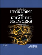
The bus topology was used in the Ethernet networks. It is simply a series of workstations or devices connected to a single cable (see Figure 13.1). Connecting workstations along a single cable is commonly referred to as daisy-chaining. This is the topology used for networks that are composed of 10BASE-2 or 10BASE-5 coaxial cabling.
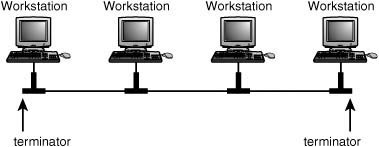
Figure 13.1. The bus topology consists of multiple devices connected to a single cable segment.
The bus topology, although simple to implement, has a few problems, including the following:
![]() The cable itself is a single point of failure for the LAN. Each end of the bus must be terminated. One broken or loose terminator can disrupt the entire LAN.
The cable itself is a single point of failure for the LAN. Each end of the bus must be terminated. One broken or loose terminator can disrupt the entire LAN.
![]() Because all workstations or devices share a common cable, tracking down a node that is causing problems on the network can be very time-consuming. For example, a loose terminator or connector on a single workstation can disrupt the entire LAN, and you might spend hours going from one node to the next checking connections.
Because all workstations or devices share a common cable, tracking down a node that is causing problems on the network can be very time-consuming. For example, a loose terminator or connector on a single workstation can disrupt the entire LAN, and you might spend hours going from one node to the next checking connections.
![]() Bus topologies for Ethernet are usually built using coaxial cable (10BASE-2 and 10BASE-5). Although less cable is used than in a star topology, these cables are more expensive than simple twisted-pair cables. In the case of 10BASE-5, the cable is not very flexible and can be difficult to route through wall or ceiling structures.
Bus topologies for Ethernet are usually built using coaxial cable (10BASE-2 and 10BASE-5). Although less cable is used than in a star topology, these cables are more expensive than simple twisted-pair cables. In the case of 10BASE-5, the cable is not very flexible and can be difficult to route through wall or ceiling structures.
In spite of its limitations when used to connect individual workstations into a LAN, the bus is a method that has often been used to join smaller groups that are connected in star formation. For example, before Fast Ethernet and Gigabit Ethernet using fiber-optic cables were developed, connections between hubs or switches in a LAN were often done using coaxial cable.
Using a Star Topology
Instead of linking workstations in a linear fashion along a single cable, the hub acts as a wiring concentrator, providing a central point in the network where all nodes connect. Figure 13.2 shows a simple LAN connected to a hub in a star configuration.
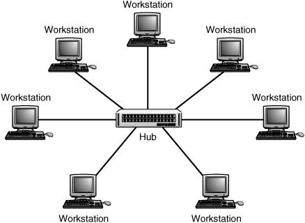
Figure 13.2. Workstations connect to a central hub in a star formation.
![]() The chapter “Bridges, Repeaters, and Hubs” on the
The chapter “Bridges, Repeaters, and Hubs” on the upgradingandrepairingpcs.com Web site and Chapter 8 discuss the star topology, which was introduced after 10BASE-T was developed.
All data that travels from one node to another must pass through the hub. A simple hub merely repeats incoming transmissions on all other ports, whereas more complex hubs can perform functions that strengthen the signal or correct minor problems.
The star topology was continued when switches were developed. A central switch looks just about the same as a hub, but it limits the collisions in a LAN dramatically. Switches, which are covered in Chapter 8, do this because they don’t rebroadcast a frame on every other port. They transmit the frame only onto the port that will get it delivered to its destination.
The star topology has only a few shortcomings when compared to the bus: More cabling is required, and the hub becomes a single point of failure. However, the benefits that the star topology has over the bus are many:
![]() Installing wiring for this type of network (twisted-pair cables, similar to telephone cables but of a higher quality) is easier than installing coaxial cabling used for the bus. Although more cable is required, the cables are also less expensive and more flexible for routing throughout a building.
Installing wiring for this type of network (twisted-pair cables, similar to telephone cables but of a higher quality) is easier than installing coaxial cabling used for the bus. Although more cable is required, the cables are also less expensive and more flexible for routing throughout a building.
![]() It is easier to detect errors in the LAN through LEDs on the hub/switch or by using a hub/switch that incorporates management software.
It is easier to detect errors in the LAN through LEDs on the hub/switch or by using a hub/switch that incorporates management software.
![]() One workstation or cabling segment that experiences problems does not disrupt the entire network.
One workstation or cabling segment that experiences problems does not disrupt the entire network.
![]() Adding and removing nodes from this type of LAN is a simple matter of plugging the cable into a free socket on the hub. Modern hubs don’t require you to place terminators on unused ports.
Adding and removing nodes from this type of LAN is a simple matter of plugging the cable into a free socket on the hub. Modern hubs don’t require you to place terminators on unused ports.
![]() If a hub fails, it can be replaced quickly with a spare by simply unplugging cables and inserting them into the new hub/switch. Alternatively, in a wiring closet with multiple hubs/switches, you could simply move users from a disabled unit to free ports on other hubs/switches until repairs could be made.
If a hub fails, it can be replaced quickly with a spare by simply unplugging cables and inserting them into the new hub/switch. Alternatively, in a wiring closet with multiple hubs/switches, you could simply move users from a disabled unit to free ports on other hubs/switches until repairs could be made.
Over the years, hubs became more intelligent, and finally switches were developed for use in local area networks. A switch works similarly to a hub, in that it centralizes the wiring of the LAN. The main difference, however, is that the switch doesn’t broadcast every frame it receives on all the other ports after it learns where a particular computer is located. A switch is similar to putting multiple bridges into one device. After the switch learns the locations of all the computers attached to it, LAN traffic can be switched between ports at a very fast rate, eliminating the collisions that would occur in a high-traffic environment using a hub.
In a modern network, switches are the preferred wiring concentrator. If you have a small home or departmental network that doesn’t generate a lot of network traffic, a cheap hub might have been a good solution a few years ago. However, you probably won’t be able to find one today at your local computer store. Instead, switches are the wiring concentrator used today. Hubs are discussed in this chapter mainly to show you how Ethernet technology has advanced.
Hybrid LAN Topologies
Switches and hubs are simple methods for creating small workgroup LANs. By using structured wiring methods, it is easy to connect hubs and switches to create larger LANs. Two popular methods used to do this are the tree and the hierarchical star.
Tree
Figure 13.3 shows a combination topology that groups workstations in a star and joins the stars along a linear bus. Most of the problems of the bus are eliminated because a single workstation cannot bring the entire LAN to a halt. You can still add or change workstations by plugging them into different ports on the same hub/switch, or on another device. Intelligent hubs and switches are capable of isolating misbehaving ports. Some do this automatically, whereas others require management intervention.
Figure 13.3. The tree topology connects star formations along a linear bus.
This is an inexpensive method that can be used to join different work departments in a building. Each local workgroup can have an administrative person who is responsible for managing the connections on the local hub or switch. The network administrator can regulate when and where new wiring concentration devices are attached to the network.
The major problem with this type of hybrid topology, however, is that if there is a problem with the backbone bus cable, in a tree topology, the network becomes segmented into individual hubs or switches. Workstations on each local device can communicate with each other, but data transfers through the network to workstations on other hubs or switches will be disrupted until the cable problem is diagnosed and corrected.
Hierarchical Star
Another method that can be used to connect hubs/switches is a hierarchical star. This method, shown in Figure 13.4, uses a central hub or switch to link other similar devices that have workstations attached.
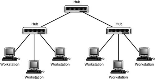
Figure 13.4. Hubs and switches can be used to form hierarchies of star networks.
This method can be used to attach up to 12 hubs to a central hub, creating a large LAN. Without using a bridge, you can connect as many as 1,024 workstations into a LAN using this method. Remembering the 5-4-3 rule, there can be up to five cable segments, connected by up to four repeaters in the path between any two nodes in the network. When working within coaxial cable–based networks such as 10BASE-2 and 10BASE-5, only three of the five cable segments can be used for computers; the other two must be used to link repeaters.
Of course, if you are using switches instead of hubs, you can extend the size of your LAN to a much greater size. The 5-4-3 rule is a requirement of legacy hubs which create a collision domain that includes all the attached computers. Switches reduce the collision domain so that there is no contention for the network media on a particular LAN segment. Keep in mind, however, that communications between switches can be a limiting factor, because the link between two switches is shared by all ports on the connected switches. Computers attached to each switch can transfer data using the full bandwidth for the particular type of Ethernet used, such as 10Mbps or 100Mbps. However, when nodes are separated by two or more switches, the bandwidth through the switch interconnections is a limiting factor, because more than one communication session can be happening at the same time between the switches.
Using a Backbone to Connect the Enterprise
Up to this point, I have discussed how to connect individual workstations in an Ethernet LAN. The hub-based LAN is a broadcast domain in which all connected stations must be capable of receiving a data transmission from all other workstations in the LAN when using hubs. Switches allow for a huge reduction in the collisions on a network, provided either that LAN communications are mostly local or that the switch has a faster uplink to the rest of the LAN.
If other technologies were not available to connect these diverse broadcast domains called LANs, it would not be possible to have the Internet, which is nothing more than an interconnection of hundreds of thousands of smaller networks.
Chapter 10, “Routers,” explains how routers work and how they can be used to create larger networks composed of multiple LANs. To put it succinctly, these devices can create a larger network because each network joined by a router is a separate network segment in itself, subject only to the limitations of individual cabling and protocol requirements. Broadcast domains are Layer 2 LAN segments that operate on the Network Layer (Layer 3) of the OSI model. Routers operate at the Network Layer and allow for a hierarchical organization of all networks connected to the Internet as well as all the separate LANs we’ve just discussed. Routers make decisions about sending packets to other networks and can use many types of high-speed protocols on the LAN-to-LAN or LAN-to-WAN connections.
Ethernet Frames
When referring to the data that is transmitted through the network, it is a common practice to call the bundles of data “packets.” However, the actual terminology for the containers of data exchanged between systems on a network varies, depending on which level of the OSI seven-layer reference model you are referring to (see Figure 13.5). For example, at the Network layer a unit of data is called a packet or datagram. The term datagram usually refers to a connectionless service, whereas packet usually indicates a connection-oriented service. You’ll find that both terms are used in the literature when discussing the Internet Protocol (IP). At the Data Link layer these datagrams are usually referred to as frames. Each frame contains the information required for it to be transmitted successfully across the network media, as well as the data that is being exchanged. At the physical level, the frame is transmitted as a series of bits, depending on the particular technology used for encoding on the network medium.
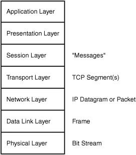
Figure 13.5. The name of the information unit changes as it passes up or down the OSI reference model stack.
![]() A good explanation of the different layers of the OSI network reference model can be found in Appendix A, “Overview of the OSI Seven-Layer Networking Reference Model.”
A good explanation of the different layers of the OSI network reference model can be found in Appendix A, “Overview of the OSI Seven-Layer Networking Reference Model.”
The data portion of the frame usually consists of bytes of information that were packaged by a higher-level protocol and then delivered to the Data Link layer for transmission inside an Ethernet frame. For example, the IP protocol specifies the header information used by that protocol, as well as the data that is being carried by the IP datagram. When the IP datagram passes down to the Data Link layer, however, all this information is contained in the data portion of the Ethernet frame.
The composition of the frame depends on the type of network. The original Ethernet frame format and Ethernet II format differ only a little from the IEEE 802.3 frame format, and the IEEE 802.5 (Token-Ring) standard defines a frame that is far different from these two. This is because Ethernet and Token-Ring have different methods for granting access to the network media and for exchanging data between network nodes.
In this chapter we will explore several frame types as they evolved with the technology. When heavy-duty troubleshooting is involved, you will need to get down to this nuts-and-bolts information to understand just what is happening on the wire.
XEROX PARC Ethernet and Ethernet II
The original Ethernet frame had defined several fields that were still used in the Ethernet II specification, including the following:
![]() Preamble—An 8-byte sequence of zeros and ones that is used to announce the start of a frame and to help synchronize the transmission.
Preamble—An 8-byte sequence of zeros and ones that is used to announce the start of a frame and to help synchronize the transmission.
![]() Destination MAC (Media Access Control) address—A 6-byte address usually expressed in hexadecimal format.
Destination MAC (Media Access Control) address—A 6-byte address usually expressed in hexadecimal format.
![]() Source (Senders) MAC address—Another 6-byte field specifying the address of the workstation that originates the frame.
Source (Senders) MAC address—Another 6-byte field specifying the address of the workstation that originates the frame.
![]() Type field—A 2-byte field used to indicate the client protocol suite in use (such as IPX, IP, and DECnet) that is to be found in the data field.
Type field—A 2-byte field used to indicate the client protocol suite in use (such as IPX, IP, and DECnet) that is to be found in the data field.
![]() Data field—A field of unspecified length that holds the actual data.
Data field—A field of unspecified length that holds the actual data.
In this original frame it was left up to the higher-level protocol to determine the length of the frame. Because of this, the Type field was an important part of the frame.
Note
The term MAC address stands for Media Access Control address. This is a 48-bit address that is hardwired into the network adapter when it is manufactured. The MAC address (sometimes called the burned-in address, hardware address, or the physical address) is usually expressed as a string of 12 hexadecimal digits, two for each byte, separated by dashes—for example, 08-00-2B-EA-77-AE. The first three hexadecimal pairs are unique to vendors that manufacture Ethernet equipment, and the last three pairs are a unique number assigned by the manufacturer. Knowing a manufacturer’s three-pair MAC digits can be a useful tool when troubleshooting network problems.
A hardware address of FF-FF-FF-FF-FF-FF is used as a broadcast address, which is used to send a single message that all nodes on the network will read.
In Figure 13.6 you can see the layout used for the original Ethernet frame.
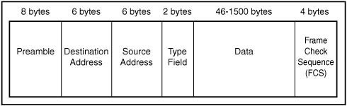
Figure 13.6. The layout of the original Ethernet II frame.
The 802.3 Standard
When the IEEE 802 project defined a frame format, it kept most of the features found in the Ethernet II frame. There are some important differences, however. In Figure 13.7, you can see the layout of the 802.3 Ethernet frame.
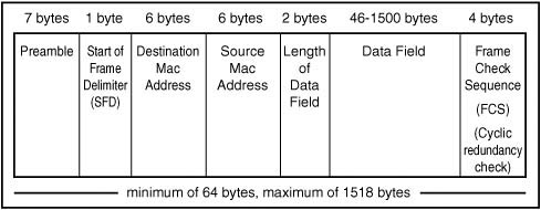
Figure 13.7. The IEEE 802.3 frame format.
The major changes included the replacement of the Type field with a new field. These 2 bytes were now used to specify the length of the data field that was to follow it. When the value in this field is 1,500 or less, you can tell it is being used as a Length field. If the value is 1,536 or larger, the frame is being used to define a protocol type.
Additionally, the preamble was reduced from 8 bytes to 7 bytes, and following it now is a 1-byte Start of Frame Delimiter (SFD). The SFD is composed of a bit configuration of 10101011 (the last byte of the earlier preamble has 10 for the last 2 bits).
The last part of the frame is a 4-byte frame check sequence (FCS). This is used to store a cyclic redundancy check (CRC) value that is calculated on the frame. The transmitting station calculates this value based on the other bits in the frame. The receiving station calculates the CRC based on the frame’s bits and compares it to this value. If they are not identical, the frame must have suffered some damage in transit and must be retransmitted.
The 802.2 Logical Link Control (LLC) Standard
In the OSI seven-layer reference model, the two lower layers are the Physical layer and the Data Link layer. When the IEEE designed its reference model, it took a slightly different approach. In Figure 13.8, you can see that the IEEE version includes a Logical Link Control sublayer and a Media Access Control sublayer on top of the Physical layer, with the Media Access Control layer straddling the boundary of the Physical and Data Link layers as defined by the OSI model.

Figure 13.8. The IEEE model differs from the OSI Reference Model.
![]() For more information about the OSI seven-layer network reference model, see Appendix A.
For more information about the OSI seven-layer network reference model, see Appendix A.
There is a rationale for incorporating some of the functionality of the OSI Physical layer in the Media Access Control layer and dividing up the Data Link layer to provide for a Logical Link Control sublayer: It is to allow different types of transmission media and methods of media access to exist on the same network.
The LLC Subheader
The Media Access Control sublayer is responsible for using the services provided by the Physical layer to get data transferred to and from remote stations on the network. This includes functions such as basic error checking and local addressing (physical, or MAC addresses).
The LLC sublayer offers services to the layers above it that can be classified into the following three types:
![]() Unacknowledged connectionless service—Some upper-level protocols (such as TCP) already provide flow control and acknowledgment functions that check on whether a packet was successfully sent. There is no need to duplicate those functions here.
Unacknowledged connectionless service—Some upper-level protocols (such as TCP) already provide flow control and acknowledgment functions that check on whether a packet was successfully sent. There is no need to duplicate those functions here.
![]() Connection-oriented service—This type of service keeps track of active connections and can be used by devices on the network that do not implement the full OSI layers in their protocols.
Connection-oriented service—This type of service keeps track of active connections and can be used by devices on the network that do not implement the full OSI layers in their protocols.
![]() Acknowledged connectionless service—This service is a mix of the other two. It provides acknowledgment of packets sent and received but does not keep track of links between network stations.
Acknowledged connectionless service—This service is a mix of the other two. It provides acknowledgment of packets sent and received but does not keep track of links between network stations.
To implement these LLC functions, IEEE 802.2 specifies a subheader that is placed into the frame directly before the data field. This LLC subheader field consists of 3 bytes. The first is the destination service access point (DSAP), the second is the source service access point (SSAP), and the last is the Control field.
The LLC Ethernet Frame
In Figure 13.9, you can see that when the LLC subheader is combined with the standard 802.3 frame, the overall size of the frame doesn’t change, but the amount of space remaining in the data portion of the frame does.
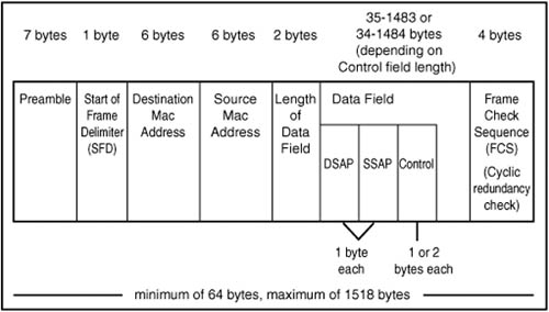
Figure 13.9. The 802.3 frame including the LLC subheader.
The 802.3 SNAP Frame
In the earlier Xerox PARC and Ethernet II frame formats, the 2-byte Type field was used to indicate the higher-level protocol for which the frame was being used. When the 802.3 frame was delineated, this field was replaced with the Length field that indicates the length of the data field.
To provide for backward compatibility with earlier networks that still needed to have something in the frame to identify the protocol that should be used, the SNAP subframe was introduced. The term SNAP stands for Sub-Network Access Protocol. It is constructed by adding additional fields to the LLC subheader, after the LLC fields:
![]() Organizationally Unique Identifier field (3 bytes)
Organizationally Unique Identifier field (3 bytes)
![]() Protocol Type field (2 bytes)
Protocol Type field (2 bytes)
The SNAP extensions must be used with the LLC subheader fields. There are no provisions for a SNAP subheader without the LLC subheader. Figure 13.10 shows the full 802.3 frame that includes the SNAP fields.
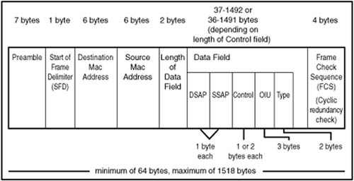
Figure 13.10. The 802.3 frame including the LLC subheader and SNAP extensions.
Note
The 802.5 specification defined the frame format used for Token-Ring networks. Token-Ring networks are fundamentally different from Ethernet networks not only in their frame formats but also in the methods used to grant access to the network media.
Fast Ethernet (IEEE 802.3u) and Gigabit Ethernet (IEEE 802.3z)
In the early 1990s, a faster version of Ethernet was developed, commonly referred to as Fast Ethernet. This standard (IEEE 802.3u) allows for Ethernet communications over both copper wire and optical fiber cables at a speed of 100Mbps. The different standards are named in the traditional way, as a concatenation of the speed, signaling method, and medium type, as described earlier in this chapter.
Fast Ethernet encompasses the 100BASE-class of Ethernet, whereas 1000BASE-denotes the Gigabit Ethernet standards. Gigabit Ethernet network cards and switches are widely available today. The specification for 10Gigabit Ethernet was finished in July 2002, and many vendors, such as Cisco, Intel, Dynatem, and others are now marketing 10Gigabit hardware.
Fast Ethernet
Fast Ethernet was designed to be compatible with existing 10BASE-T networks. It uses the same frame format, and it still uses the CSMA/CD medium access method defined in the 802.3 standard. What makes it even nicer as an upgrade path for an existing network is that it can interoperate on the same wiring as 10BASE-T. That is, with an intelligent hub (or switch) that can detect the speed being used by a particular workstation’s network adapter card (autosensing), you can use both types on the same network and they can talk to each other. The hub/switch takes care of buffering data to enable transfers between ports operating at different speeds. If your network still contains computers connected using 10BASE-T, it is time to upgrade to Fast Ethernet. You can do so gradually, as your schedule permits, because autosensing ports and network adapter cards allow for both 10BASE-T and 100BASE-T nodes on the same LAN.
0 100BASE-T
One of the nice things about migrating to 100BASE-T from older technology is that you can use existing wiring if the building has Category 3 cabling already in place. The 100BASE-T standard is defined for use with either twisted-pair wiring (100BASE-TX and 100BASE-T4) or optical fiber (100BASE-FX). 100BASE-T4 is the only standard that allows for the use of Category 3 wiring, so an upgrade path exists for those who cannot afford the expense of rewiring a building at this time. Running new cabling is one of the more expensive items when upgrading a network. Yet if you are still using anything less than Category 5 cabling, you should consider this expense something you should incur now, rather than later. A speed of 10Mbps is just too slow for most applications today in a large enterprise network. Applications and data files continue to grow, and 100Mbps is now considered to be the minimum bandwidth for most wired LANs.
There is an important difference between 100BASE-T4 and 100BASE-TX: They do not use the same cable pairs to transmit and receive data. 100BASE-T4 uses all four cable pairs and a different signaling technique.
For sites that were forward-thinking and installed Category 5 cables when creating a 10BASE-T network, upgrading to a 100Mbps network will prove that the investment was worthwhile. This twisted-pair version of the 100BASE-T specification can be used on this cabling or on the shielded twisted-pair (STP) cables that are usually found on Token-Ring networks. The 100BASE-TX standard is based on the ANSI TP-PMD (Twisted-Pair Physical Medium Dependent) specification. The maximum segment length is 100 meters, but again you must remember to include the distance from where the horizontal wiring terminates at the work area faceplate to the workstation.
The total distance through the LAN can be as many as 200 meters, incorporating up to two hubs. There are two classes of hubs: Class I and Class II. Keep in mind that hubs are considered to be legacy devices today, and you will find this equipment only in older networks. You will probably not be able to purchase new devices of this sort. However, this information may prove useful if your network has not yet been upgraded to newer technology. Here’s a rundown on the classes of hubs:
![]() Class I hubs—A standard 10BASE-T hub receives data from a segment and outputs the same signal on the other segments that are attached to its ports. Because three formats are used by 100BASE-T, a standard hub limits a particular LAN to having only one type of 100BASE-T segment. A Class I hub solves this problem by translating the incoming signals from one format to another before sending the signal back out on the other ports. Because of the overhead involved in the signal processing, the standard limits a network to using only one Class I hub.
Class I hubs—A standard 10BASE-T hub receives data from a segment and outputs the same signal on the other segments that are attached to its ports. Because three formats are used by 100BASE-T, a standard hub limits a particular LAN to having only one type of 100BASE-T segment. A Class I hub solves this problem by translating the incoming signals from one format to another before sending the signal back out on the other ports. Because of the overhead involved in the signal processing, the standard limits a network to using only one Class I hub.
![]() Class II hubs—A Class II hub operates with only one media type—100BASE-TX. It performs no signal translation and acts as a simple multipoint repeater. There can be a maximum of two Class II hubs in the collision domain.
Class II hubs—A Class II hub operates with only one media type—100BASE-TX. It performs no signal translation and acts as a simple multipoint repeater. There can be a maximum of two Class II hubs in the collision domain.
0 100BASE-T4
For those networks that have a heavily installed base of Category 3 or Category 4 cabling, this version of 100BASE-T provides an upgrade path. This standard uses half-duplex signaling on four pairs of wires, as opposed to the two pairs used by 10BASE-T and 100BASE-TX. Three of the wire pairs are used for actual data transmission, and the fourth pair is used for collision detection. The three pairs used in transmission each operate at only 33.3Mbps, for a total of 100Mbps (called the 4T+ signaling scheme). Additionally, a three-level encoding scheme is used on the wire instead of the two-level scheme used for most other media. Because 100BASE-T4 requires special hardware, such as network adapter cards and hubs, and because it operates only in half-duplex mode, it shouldn’t be considered for a new installation, but only as a possible upgrade path when other options cannot be justified.
0 100BASE-FX
Fiber-optic cable provides the greatest distance for Fast Ethernet. 100BASE-FX, using a two-strand cable (one strand for transmission and one for receiving data and detecting collisions), can achieve a distance of up to 2 kilometers.
Fiber is a good choice for use as a backbone in the network. Unlike copper wire cables, which use electrical impulses for communications, fiber uses pulses of light. This also makes fiber cable a better choice in an environment with a lot of electrical interference. Because fiber-optic cable emits no electrical signals itself (which can be intercepted to eavesdrop on the network), it is also ideal in a situation in which security is a great concern. Finally, optical fiber provides a built-in capability that will certainly be pushed to greater transmission speeds as new standards develop.
Gigabit Ethernet
In 1998, the 802.3z standard for Gigabit Ethernet was finished and includes the following:
![]() 1000BASE-SX—Using multimode fiber for short distances. Up to 300 meters when using 50-micron multimode fiber, or 550 meters when using 62.5-micron multimode fiber.
1000BASE-SX—Using multimode fiber for short distances. Up to 300 meters when using 50-micron multimode fiber, or 550 meters when using 62.5-micron multimode fiber.
![]() 1000BASE-LX—Using single-mode fiber for distances up to 3,000 meters, or using multimode fiber for up to 550 meters.
1000BASE-LX—Using single-mode fiber for distances up to 3,000 meters, or using multimode fiber for up to 550 meters.
![]() 1000BASE-CX—Using twisted-pair copper cables rated for high performance for up to 25 meters. Intended for use in wiring closets.
1000BASE-CX—Using twisted-pair copper cables rated for high performance for up to 25 meters. Intended for use in wiring closets.
![]() 1000BASE-T—For use over Category 5 twisted-pair cables for a maximum distance of up to 100 meters.
1000BASE-T—For use over Category 5 twisted-pair cables for a maximum distance of up to 100 meters.
Note
The UTP version of Gigabit Ethernet is known as the IEEE 802.3ab standard. Because of its short range (25 meters) it is intended mainly for use in connecting equipment in wiring closets.
Gigabit Ethernet is designed to mesh seamlessly with 10/100Mbps networks but you will need special hardware that is rated for gigabit standards. Gigabit Ethernet uses the same CSMA/CD medium access protocol and the same frame format and size. It is ideally suited for use as a network backbone to connect routers and hubs or other types of repeaters, due to both its compatibility with existing technology and the speeds of transmission that can be accomplished. For example, another feature that will make Gigabit Ethernet a choice for the network backbone is the capability to run in full-duplex mode on nonshared connections. In this mode two connections—one for send, one for receive—are used to transmit data so that collision detection will not be needed. This will enable faster data transmissions between switches used to connect LANs.
The IEEE 802.3z standard for Gigabit Ethernet added another field to the basic 802.3 frame: the Extension field. This field is appended to the frame after the Frame Check Sequence field and is used to pad the frame so that its minimum size is 512 bytes instead of the 64 bytes used by slower standards. This increased size is needed only when operating Gigabit Ethernet in half-duplex mode when collision detection is still involved. This field is not needed in full-duplex mode.
Another method for making faster transmissions with Gigabit Ethernet is to reduce the overhead involved with using CSMA/CD for every single frame that is sent on the network. A mode of operation called burst mode was added in the 802.3z standard that provides for sending multiple frames, one after the other, after gaining access to the network media. This is accomplished by inserting special “extension bits” in the interframe gaps between normal frames. These extension bits keep the wire active so that other stations do not sense it as being idle and attempt to transmit.
Tip
Another proposal that is being considered by many companies is one called jumbo frames. This proposal, the work of Alteon Networks, Inc., raises the overall length of an Ethernet frame (on a full-duplex mode link) to 9,018 bytes. It is not practical to go much further past this 9,018-byte limit, because the CRC error detection/correction mechanism used by Ethernet cannot be as precise when frames get much larger than this. However, this is a dramatic increase over the standard 1,500-byte Ethernet frame.
Gigabit Ethernet is currently being widely deployed for use in local area network backbones to connect high-capacity servers or switches. This role was earlier played by Fast Ethernet (and, of course, before that by 10Mbps Ethernet). As one technology advances to the desktop, another replaces it in the backbone. As we get into the area of high-speed transport protocols, Gigabit Ethernet might now start competing in areas that were previously the domain of ATM and Frame Relay, which, in the past, were typically used to carry IP data. Although SONET is widely deployed as a metropolitan area network (MAN) solution, the faster Ethernet gets, the harder it is to justify carrying it by other transport protocols when used in a switched environment.
As IP approaches and passes the 10Gigabit speed limit, it will no doubt become an important player beyond network backbone usage. Because Ethernet is Ethernet (as long as you use the right interconnecting switches!), it’s easier to manage a single transport protocol than to try to manage mapping one onto another. Gigabit Ethernet is definitely in your future, whether or not it is viable for you now, and 10Gigabit Ethernet products are already on the market, if you can justify the cost.
0 10Gigabit Ethernet (IEEE 802.3ae)
With other WAN protocols already in use on long-distance backbones for large networks and the Internet, you might not think that Ethernet, basically a LAN protocol, would need to be developed beyond what is required in a typical LAN. With switching, increasing speeds, and full-duplex connections, Ethernet has faired far better than other LAN technologies in the past 30 years. Just compare it to Token-Ring. However, there is no reason why Ethernet should not be pushed further, and there are advantages to doing so.
10Gigabit Ethernet keeps the standard 802.3 frame format and the same minimum/maximum frame sizes as previous versions of Ethernet. However, half-duplex operation is no longer supported, and 10Gigabit Ethernet does not have any provisions for using a shared network media—you’ll use switches, not hubs. By removing the half-duplex feature and removing the need for CSMA/CD, the distances that Ethernet can now cover are limited only by the physical network media and the signaling method used. Another important reason for dropping the half-duplex option is the fact that although Gigabit Ethernet supports half- and full-duplex modes, customers have almost unanimously chosen full-duplex products.
At the Physical layer, the 802.3ae specification provides for two Physical layer (PHY) types—the LAN PHY and the WAN PHY. The PHY layer is further subdivided into the Physical Media Dependent (PMD) part and the Physical Coding Sublayer (PCS). The PCS is concerned with how data is coded onto the physical network. The PMD represents the physical components, such as the laser or the light wavelength used.
The LAN PHY and the WAN PHY will both support the same PMDs. The PMDs for 10Gigabit Ethernet range from using an 850 nm laser on multimode optical fiber (50.0 microns) for short distances (up to 65 meters) to using a 1550 nm laser on single-mode fiber (9.0 microns) for up to 40 kilometers. The LAN PHY will be designed to operate with existing Gigabit Ethernet LAN encoding, but at a faster rate.
The WAN PHY is a separate physical interface that allows for longer distances, with an optional interface under consideration that would allow 10Gigabit Ethernet to use SONET/SDH as a transport. SONET OC-192 provides a payload that is close to the 10Gigabit speed offered by Gigabit Ethernet. All that is necessary to connect the two is to provide some simple buffering mechanisms in connecting network equipment. Because SONET/SDH is a widely deployed technology, this means that it will not require WAN providers to make a huge investment in new cables to carry 10Gigabit Ethernet traffic. Instead, it becomes a value-added service they can offer to their customers. End-to-end Ethernet connections for a wide area network without the time-consuming need to convert from one frame format will make managing WANs simpler because there will be fewer factors that can go wrong.
However, the current outlook is to use 10Gigabit Ethernet as the WAN protocol. It is estimated that it will be cheaper to implement 10Gigabit Ethernet services than to provide a similar T3 solution in a MAN or WAN environment.
Of course, there are critics who point out that Ethernet cannot provide the same guaranteed Quality of Service (QoS) that ATM does. And, when compared to SONET and other high-speed transmission protocols, Ethernet comes up lacking in the management tools area. However, the simplicity of Ethernet and the fact that it costs so much less than other WAN solutions make it very attractive for many markets.
Ethernet Problems
Because traditional Ethernet uses a shared network medium, tracking down problems can at times be difficult. Problems can arise from simple things such as bent or broken cables, to loose connectors, and faulty network adapters. The most common problem you will find, however, is in controlling collision rates as the network size increases.
Collision Rates
Keeping the network healthy requires that you be sure that all physical components are functioning normally and at optimal levels of performance. However, you still need to monitor the network to be sure that other factors are not limiting the amount of real data that can travel through the network.
Although collisions are a normal event in legacy Ethernet networks, and indeed are expected for a network based on Ethernet technology, it is always possible for excessive collisions to cause a significant degradation of performance that will be noticeable to end users.
Collisions and Network Utilization
When a device begins to experience collisions at a rate that is 1% of the total network traffic, you might have a problem. Another statistic to watch when monitoring the network is utilization. In theory, you might expect that a network operating at 10 million bits per second would actually be capable of transmitting that much data on a continuous basis. However, that is not the case. In most Ethernet networks, the actual utilization rate is only 40% before performance begins to degrade rapidly. As utilization rises, so do collisions.
Note
Keep in mind that in this section collisions are discussed, and collisions occur only on shared network media. If switches are used (in full-duplex mode), then collisions do not occur. If you are using hubs, it might be a simple solution to increase your network bandwidth utilization by simply replacing older hubs with newer switches.
If the network topology rules are followed and the network utilization is low, excessive collisions might be due to a faulty network card that is not listening to the network. You can find more information on this scenario later in this chapter in the section “Faulty Network Adapters.”
Detecting Collisions
A simple method for determining how many collisions are occurring is to look at the LED lights on the hub or switch. Most hubs have an LED that lights up when a collision is detected. If you notice that this light is flashing continuously or very frequently, investigate further to determine whether the rate is excessive. If it is, take action to reduce it. Using network monitoring software, you can determine the utilization rate of the network. When you get above a 30%–40% utilization rate, it’s time to start thinking of segmenting your LAN into smaller collision domains.
LAN analyzers and monitoring tools can aid you in counting the number of collisions that are occurring. Management consoles that employ SNMP and RMON probes can be useful for collecting statistical information used to localize segments in the network that experience high collision rates. The historical data maintained by RMON can be analyzed and stored for use in creating baseline data that you can use to judge network performance. If you are about to purchase a new switch or hub, check the documentation to see whether it supports telnet management sessions. This is a common feature on even low-end hubs now. In a small network with only a few switches, using built-in management software is a lot cheaper than investing in network management software like SMS or HP OpenView.
Collision Types
A good network analyzer gives you a lot of statistical information. When it comes to collisions, there will most likely be more than one kind of statistic to help point out the cause of the collision.
Local Collisions
A local collision (also called an early collision) is a collision that happens on the local segment during the transmission of the first 64 bytes of a frame. This is the most common type of collision you will see on a network segment, and usually does not indicate a hardware problem. This type of collision happens when two different stations on the LAN detect that nothing is being transmitted on the wire and both begin to transmit at about the same time. The result is a frame called a runt, named because only part of the frame was transmitted successfully before the collision event occurred. The Ethernet specifications take into consideration this expected event, and both stations use the backoff algorithm to delay transmission.
When high levels of early collisions are occurring, look to see whether the utilization on the segment is nearing or surpassing 40%. If this is the case on a regular basis, the segment is probably overloaded. Consider using a switch to limit collisions. If you can identify a particular node that is experiencing a high rate of local collisions, there might be a hardware problem. Check the connectors that join it to the network; if no fault is found there, try replacing the network adapter card to see whether that is the problem.
Late Collisions
A late collision occurs when two devices on the network start to transmit at the same time and do not detect the collision immediately. A network segment that is too long usually causes this kind of collision. If the time it takes to put the frame on the network is shorter than the amount of time it takes for the frame to travel to the node that is the greatest distance away, neither device will know that the other has started transmitting until after the first 64 bytes (the minimum frame size) have been put on the wire.
For example, suppose that workstation A begins to transmit a frame and finishes transmitting before the signal reaches workstation B, which has been cabled to the network at a distance that exceeds the specs. Workstation B, thinking that the wire is clear, begins to transmit its frame just before the signal from workstation A reaches it. Of course, because workstation B is closest to the collision event, it detects the collision. However, because workstation A has finished transmitting the frame, it has also stopped listening to detect whether a collision has occurred. The end result is that workstation A thinks it was able to successfully transmit the frame. It has no idea that a collision has occurred.
Late collisions do not cause a frame to be retransmitted, simply because the NIC does not know that a collision has occurred. It is up to a higher-level protocol to determine that something has caused an error and to request retransmission.
If the LAN is experiencing high levels of late collision events, check for topology problems. This includes not only excessive cable lengths, but also using too many repeaters or other devices. If no apparent problems are found and the network appears up to specifications, there is probably a hardware problem. Try to locate the offending NIC or cable by looking at the addressing information decoded by a LAN analyzer.
Sampling Intervals
When monitoring for collisions, don’t jump to conclusions when you see only sporadic increases. Take samples several times during the workday, and try to correlate them with the functions being performed by users on the network at that time. Sometimes it is the actual day that matters, and not the time. For example, at the end of a month or a quarter, many business functions are performed—such as accounting reports—that generate large amounts of network use. It is a simple matter to determine which month-end tasks need to be done first and in what order. Sometimes scheduling is all that is necessary to solve a network congestion problem.
An overall average of the number of collisions that occur per second, along with the network utilization rate, is useful in determining whether the network is becoming saturated. Information about peak levels is useful for designing user work patterns so that the network is used more efficiently.
Reducing Collisions
There are several reasons why collisions will occur at excessive rates. Some of those reasons include ignoring topology rules, faulty hardware, and an overloaded segment (too many users).
Incorrect Network Topology
If you use segments that exceed the length permitted by your network topology, some devices on the network might not detect that the network is in use until a transmission by another node is well underway. Check your cable lengths and be sure they are within the standards. When it comes time to expand the LAN, you should never haphazardly add new segments by simply attaching a new repeater, hub, or bridge to the network. For this reason, it is important to keep an up-to-date map of the physical topology of the network so that you can plan additions before you implement them.
Remember that, for 10BASE-T, workstations can be no farther than 100 meters from the hub. In addition, the 5-4-3 rule states that there can be a maximum of five cable segments on the LAN, with a maximum of four repeaters or concentrators, and only three segments can have nodes attached. For Fast Ethernet and Gigabit Ethernet, be sure that you don’t exceed the topological metrics imposed by the physical network media used.
Faulty Network Adapters
One particular problem is an adapter that does not sense the carrier signal due to faulty hardware, and begins to transmit whenever it wants to, thinking that the wire is available. In Chapter 7, “Network Interface Cards,” you will find a more detailed discussion of troubleshooting NICs. However, a basic strategy to follow is to replace the suspect device and, if that does not solve the problem, try to use a different cable to connect the NIC to the network or try to reseat the NIC in another slot in the computer. When replacing the device, be sure to use a substitute that is known to be in good working order. The same goes for replacement cables. Another troubleshooting tactic is to use the diagnostic software provided by the network adapter’s manufacturer.
Top Talkers
There are only so many devices you can place on a network in the same broadcast domain before performance begins to suffer. A small number of high-performance computers that generate a lot of network traffic can produce the same result. Remember that as utilization rises, so do collisions. So when you are experiencing a high collision rate and the network segment’s utilization approaches or exceeds the 40% mark, it’s time to consider segmenting the LAN using a switch or similar device. A switch, which can be used to give high-end servers a full-duplex connection, is an ideal choice when a local segment contains both end users and powerful servers that are “top talkers.”
Ethernet Errors
Most of the problems addressed in the following sections can be remedied by making a simple change to your network. If you are still using hubs, consider upgrading to switches instead. Although it is possible to continue to use CSMA/CD-intensive Ethernet devices (and therefore have to worry about collisions), many new applications that rely on a large bandwidth to access multiple servers and other network resources will end up causing network traffic delays. It doesn’t matter how good the new application is if it can’t get data pushed through a slow network pipe. And the move today is toward centralizing servers rather than installing large applications or data on desktop computers.
However, if you are still using hubs and other equipment that enables collisions to occur, this section might help you in solving some problems that can come up.
Simple Error Detection
A lot of things can go wrong when you send hundreds of thousands of bits out on a copper wire, hoping they arrive at their destination in the proper order and with no changes. With the higher speeds that are being achieved with new technologies, detecting errors is becoming increasingly more important.
The simplest method for error detection is called a parity check. An example of this method is transmitting characters using the ASCII 7-bit character set with an eighth bit added. If even parity is being used, the eighth bit is set to zero or one, whichever makes the number of “1” bits an even number. If odd parity is being used, the eighth bit is selected to make the number of “1” bits an odd number. The receiving station can calculate what the parity bit should be by examining the first seven characters and making a simple calculation. This scheme easily breaks down, however, if more than one bit was transmitted in error.
Also, this type of error checking operates at the byte level and is not very useful for determining whether an error exists in a frame of data that is 1,518 bytes in length. Ethernet frames use the frame check sequence (FCS) to check the integrity of the frame. Higher-level protocols employ other methods to ensure that packets arrive intact and in the correct order. Besides errors involving corrupted frames that can be detected using the FCS, there are other types of common Ethernet errors. This chapter takes a quick look at the most common errors and their possible causes.
Bad FCS and Misaligned Frames
The most obvious place to start is the frame check sequence (FCS) error. The MAC layer computes a cyclic redundancy check (CRC) value, based on the contents of the frame, and places this value in the FCS field. The receive station can perform the same calculation and, by checking its result against that stored by the transmitting station, can determine whether the frame has been damaged in transit.
It is possible that this value was incorrectly computed by the sending station due to a hardware problem where this MAC layer function is performed. It also is possible that the adapter that is sending out this frame is experiencing some other kind of problem and is not correctly transmitting the bits on the wire. As with most errors, the problem might also lie with noise on the cables that are connecting the network.
When you monitor a level of bad FCS errors that exceeds 2% or 3% of the total utilization of bandwidth on the network, you should begin troubleshooting to find the offending device. Using a LAN analyzer, you can usually locate the source address of the faulty device and take corrective action.
To determine whether the suspected device is indeed the source of the error, first power it off and continue to monitor the network. If errors continue to occur but another address appears to be the source, there might be cabling problems on the network. If the errors disappear when the device is powered off, you can troubleshoot it further to locate the cause. You should look for the following:
![]() Bad connector—Check the connector that attaches the network cable to the workstation’s adapter card.
Bad connector—Check the connector that attaches the network cable to the workstation’s adapter card.
![]() Bad port—If the workstation is connected to a hub or a switch, the port on that device might be causing the problem. Also, be sure to check the connector on that end of the cable segment.
Bad port—If the workstation is connected to a hub or a switch, the port on that device might be causing the problem. Also, be sure to check the connector on that end of the cable segment.
![]() Bad cable—There’s always the chance that a cable has been damaged or disconnected. If nothing you try solves the problem, use a diagnostic tool, such as a Time domain reflectometer, to search for problems in the network cabling.
Bad cable—There’s always the chance that a cable has been damaged or disconnected. If nothing you try solves the problem, use a diagnostic tool, such as a Time domain reflectometer, to search for problems in the network cabling.
![]() Malfunctioning network card—Finally, replace the network adapter card on the workstation to see whether this clears up the problem.
Malfunctioning network card—Finally, replace the network adapter card on the workstation to see whether this clears up the problem.
Because a frame is composed of bytes—units of 8 bits—the resulting frame should be evenly divisible by eight when it reaches its destination. If it’s not, something has gone wrong. This type of error is called a misaligned frame, and the frame usually has a bad FCS as well. The most common reason for this type of error is electrical interference on the network or a collision. Another common cause is an incorrect network topology, in which more than two multiport repeaters are used in a cascaded fashion.
You can troubleshoot this type of problem using the same methods as for a bad FCS error. Of course, if you are aware of a topology problem, you already know where the problem is.
Short Frames (Runts)
A runt is an Ethernet frame that is smaller than the minimum size of 64 bytes. Remember that the transmitting NIC must transmit a packet for an amount of time that allows it to make a round trip in the local broadcast domain before it stops transmitting. Otherwise, the transmitting NIC cannot effectively detect a collision. The maximum propagation time for Ethernet segments is 51.2 microseconds, which is the amount of time it takes to transmit about 64 bytes. This minimum frame size does not include the preamble.
There are many reasons why short frame errors can occur on the network wire. Some of these short frames stem from the following:
![]() Collisions
Collisions
![]() Faulty network adapters
Faulty network adapters
![]() Topology errors
Topology errors
If a runt frame has a valid FCS value, which indicates that the frame appears to be internally valid, the problem is most likely in the network card that generated the frame. If the FCS value is not correct for the frame’s contents, the problem most likely is due to collisions or topology.
Collisions are a normal event for Ethernet. Sometimes, however, the byproduct of a collision results in signals on the wire that are interpreted as a short frame. If you are experiencing a lot of errors that indicate short frames, check the utilization statistics for the segment. If the peak utilization is heavy, but ordinary overall utilization is acceptable, try to rearrange user workloads so that some tasks are delayed to a time when the network is less busy. Another option is to place high-end workstations that use a lot of bandwidth on a separate LAN segment, and thus free up bandwidth on the other segment. Connect these segments using a switch or router, and this might solve your problem.
If the utilization values for the segment are low, you might want to investigate further to determine the workstation or device that is originating the short frames, and subject the NIC to diagnostic testing to determine whether it is at fault. This can be a difficult task because a lot of errors of this type occur with frames so short that you cannot determine the source address.
Ignoring the topology rules of Ethernet also can produce short frames. A common error is to use more than four repeaters for a single collision domain, which can result in short frames appearing on the wire.
Giant Frames and Jabber
Sometimes, a network adapter produces frames that are larger than the maximum allowable size. The opposite of a short frame error is a giant frame error. According to the rules that govern Ethernet communications, the maximum size of a frame is 1,518 bytes, excluding the preamble bits. Reasons for oversized frame errors appearing on the wire include these:
![]() A defective NIC that is transmitting continuously (also known as a “chattering” NIC).
A defective NIC that is transmitting continuously (also known as a “chattering” NIC).
![]() Bits indicating the length of the frame have been corrupted and indicate that the frame is larger than it actually is.
Bits indicating the length of the frame have been corrupted and indicate that the frame is larger than it actually is.
![]() There is noise on the wire. Random noise on a faltering cable can be interpreted as part of a frame, but this is not a very common reason why oversized frame errors occur.
There is noise on the wire. Random noise on a faltering cable can be interpreted as part of a frame, but this is not a very common reason why oversized frame errors occur.
Finding the location of a device that is malfunctioning might be simple if the LAN analyzer you are using is capable of detecting a source address. You can power off or disconnect the suspected node to determine whether it is the cause of the problem. It is possible that you will not be capable of detecting the address of the NIC if the malfunctioning card is repeatedly sending out meaningless signals. In that case, you need to look at each workstation on the segment, one by one, and try to remove them from the network to see whether the condition clears up.
The term jabber is sometimes used to refer to oversized frames, but it is really just a catch-all term used to indicate that a device on the network is not following the rules and is behaving improperly when it comes to signaling on the network. A defective NIC might be sending out frames that are larger than allowed, or it might be signaling continuously.
This type of error can literally bring down an entire segment because an adapter that continuously transmits does not give any other station a chance to use the wire. Because stations are supposed to check the network medium to see whether it is busy before transmitting, the workstations that are functioning normally simply wait until the network becomes available.
Multiple Errors
Depending on the tool used to monitor the network, the number of different error types you see might vary. For example, misaligned frame errors usually have a bad FCS field as well. Some analyzers record two errors for one event, whereas others might record the error as one type or the other.
Check the documentation for the product you use to determine whether this is true for your particular product.
Broadcast Storms
Broadcast storms usually occur when devices on the network generate traffic that causes even more traffic to be generated. Although this additional traffic might be due to physical problems in the network devices or the network media, it is usually caused by higher-level protocols. The problem with trying to detect the cause of this type of situation is that when it occurs, you are usually unable to access the network. Broadcast storms can slow down network access dramatically, and can sometimes bring it to a halt.
When monitoring the network for broadcast activity, you normally see a rate of 100 broadcast frames per second or less. When this value increases to more than 100 per second on an ongoing basis, there might be a problem with a network card, or you might need to segment the collision domain into smaller parts. You can use routers to do this because they do not pass broadcast frames unless they are configured to do so. Many bridges also can be configured to detect excessive broadcasts and to drop broadcast packets until the storm subsides.
Monitoring Errors
There are many tools you can use to monitor errors on the network. A network analyzer—for example, Network Sniffer from Network General—displays information about frames that contain errors, including runts, CRC, and alignment errors. Some software-based applications, such as the Network Monitor tool included in Windows NT Server or Microsoft’s System Management Server, enable you to view statistics about frames dropped, CRC errors, and broadcasts. Simpler handheld tools also might provide functionality that enables you to detect when these errors are occurring.
For a network that requires centralized management and control, an SNMP management console application, using RMON, can be used both to monitor the network for Ethernet errors and to set up alerts that trigger notifications so that you can become aware of problems immediately. The history group of RMON objects allows you to record error counts over a period of time and use them for later analysis to assist in troubleshooting.
![]() You can find more information about SNMP, RMON, and network monitoring tools in Chapter 48, “Strategies for Troubleshooting Network Problems,” and Chapter 49, “Network Testing and Analysis Tools.” For more specific information on how to isolate Ethernet problems, see the chapters devoted to network cards, cables, hubs, switches, and routers.
You can find more information about SNMP, RMON, and network monitoring tools in Chapter 48, “Strategies for Troubleshooting Network Problems,” and Chapter 49, “Network Testing and Analysis Tools.” For more specific information on how to isolate Ethernet problems, see the chapters devoted to network cards, cables, hubs, switches, and routers.
Depending on the vendor, many internetworking devices—such as routers and intelligent hubs—are equipped with management software that can be tapped to display error statistics when you do not need a more extensive application (such as a management console). Checking statistical information on a regular basis and keeping a log of it is a good idea. When you keep track of error conditions on a regular basis, you can begin to solve problems more quickly because you can determine whether the current situation matches a previous problem.