Two large corporations—a computer company hoping to develop technical expertise in new areas, and a publisher seeking new markets—formed a partnership to develop a multimedia system for university engineering education. The project team was diverse. Most of its members came from the computer company, but they consisted of scientists, programmers, and engineers from many specialty areas, including information retrieval, multimedia systems, human-computer interaction, and artificial intelligence. The team also included one representative from the publishing company and two university professors who served as education consultants.
The envisioned system would make it easy for professors to create multimedia case studies for class activities in which students worked with case study content—individually and in groups—in an open-ended manner, analyzing them and preparing multimedia reports. All communication regarding the assignments (distribution, questions, submission, and evaluation) would take place over a network. The system must be accessible to both teachers and students, although the concrete activities of the two user groups would be quite distinct. A set of instructional modules would be built to demonstrate and test the capabilities of the system. The project required digitization of substantial content—video, text, sound, and images—in support of the example course modules.
The first few months culminated in an all-hands meeting, during which a prototype was to be demonstrated. In fact, two prototypes were demonstrated at this meeting, with rather different objectives. The core team built a rapid prototype in Smalltalk, showing a very basic user interface but including a skeleton for underlying system services. The consultants used an interface scripting language to enact user scenarios. The core team’s prototype looked less finished, but was a concrete beginning on an actual implementation, whereas the consultants’ prototype looked very finished, but was only designed to focus goals and issues. The project team could not escape the obvious, albeit superficial, competition between the prototypes; the representative from the publishing company (the least technically sophisticated member of the entire team) was clearly beguiled by the consultants’ prototype. Tension between the two early visions emerged, with long-lasting impacts on the project (see Carroll 2000 for more discussion).
A logical entailment of iterative design is that prototypes are constructed and evaluated to guide redesign and refinement. A prototype is a concrete but partial implementation of a system design. Prototypes may be created to explore many questions during system development—for example, system reliability, bandwidth consumption, or hardware compatibility (Sommerville 1992). A user interface prototype is a prototype built to explore usability issues (Wasserman & Shewmake 1982).
Prototypes can be developed in service of many goals—to discover or refine user requirements, inspire or explore design ideas, share or co-develop designs with user participants, make a precise test of specific open issues, and share or deploy early implementation efforts. The most common use of prototypes in usability engineering is to collect usability test data. But as illustrated in the sidebar on page 203, the goals of prototyping are not always clear even within a highly motivated team of experts. The common-sense understanding of prototyping as a way to try out ideas can lead to quite different interpretations and efforts in the minds of different project stakeholders.
There are many options for building user interface prototypes. These techniques vary a great deal in terms of (1) the cost and effort of producing the prototype and (2) the fidelity and generality of the resulting artifact. Table 6.1 lists some of the most common prototyping techniques used in usability engineering practice, ordered roughly by these two dimensions. For example, a team can sketch a series of screens in just a few minutes, but creating a computer-based animation may take days or weeks. On the other hand, the animation will seem more realistic and more impressive.
Table 6.1 Common approaches to prototyping in usability engineering.
| Type of Prototype | Description |
| Storyboard | Sketches or screen shots illustrating key points in a usage |
| narrative | |
| Paper or cardboard | Fabricated devices with simulated controls or display |
| mock-up | elements |
| Wizard of Oz | Workstation connected to invisible human assistant who |
| simulates input, output, or processing functionality not | |
| yet available | |
| Video prototype | Video recording of persons enacting one or more |
| envisioned tasks | |
| Computer animation | Screen transitions that illustrate a series of input and |
| output events | |
| Scenario machine | Interactive system implementing a specific scenario’s |
| event stream | |
| Rapid prototype | Interactive system created with special-purpose |
| prototyping tools | |
| Working partial | Executable version of a system with a subset of intended |
| system | functionality |
An important responsibility for usability engineers is choosing an appropriate and cost-effective prototyping technique. This requires a thorough understanding of the goals of the prototype and the resources available for building and then evaluating the prototype.
6.1 Exploring User Requirements
In the early stages of system development, prototypes may be built to explore ideas about new technology, document or analyze current tasks, or share visions of what the future may hold. A prototype is created to illustrate some aspect of current or future use, and is shared with a group of potential users or other stakeholders. Questions, reactions, and ideas for changes are recorded and used to better understand problems or opportunities.
The fact that a project is in its early stages does not mean that only modest or rough prototypes can be constructed. A company that wants to encourage its clients or employees to “think out of the box” may use high-quality multimedia simulations, or actors role playing a situation to present a vision that is dramatically removed from current practice. One famous example is the Knowledge Navigator video created by Apple Computer (Dubberly & Mitch 1987; see “Video Prototyping” sidebar). In this sense, a science fiction movie often includes video prototypes of future interactive system designs.
However, most projects do not have the resources to build a polished vision of future human-computer interactions. Fortunately, less expensive techniques work well for many goals. In the science fair project, we used informal screen Sketches to explore information layout possibilities (Figures 4.16 and 4.17). We mocked up a felt board to use in participatory design sessions (Figure 4.19). We also developed summary views of a series of screens, to examine a user interaction sequence that was of particular concern (Figure 5.7). These can all be seen as variants of the storyboard technique, where one or more sketched or computer-drawn pictures are used to explore a specific scenario.
The choice of prototyping technique must take into account the goals and resources of the project team, the audience, and the manner in which it will be presented. On the one hand, a business audience of managers, salespeople, or marketing professionals is accustomed to high-quality graphics, so hand-drawn sketches may evoke a poor response. On the other hand, a single sketch or storyboard that is accompanied by a vivid and compelling scenario narration may capture the imagination of such an audience just as well as an expensively produced video or computer animation (Erickson 2000).
The presentation context of the prototype is also a key factor. If the team offers little orienting information, assuming that a prototype will be self-evident, viewers will rely on their own backgrounds and expectations to make sense of it. Someone who is not familiar with technology or prototyping techniques may interpret a simulation of the future as reality, or at least as a feasible project outcome. Unless this is the intended goal, the prototyping team must carefully describe just what the prototype represents and why it is being demonstrated.
Even when sufficient context is provided, a high-quality prototype can have unintended effects (Tradeoff 6.1). A futuristic vision is exciting and can provoke intense discussions of what the system is all about. But it can also cause premature commitment to the details of the vision. To create a convincing vision, the prototyping team must choose and simulate specific user goals, system displays, and input and output episodes. If the result is attractive and persuasive, decision makers may simply conclude that they want what they have seen, and refuse to support the more iterative analysis and design process needed to develop a usable system. Premature commitment can be especially troublesome when the prototype is computer based, because the team may have difficulty explaining how little has really been implemented.
High-quality graphics and animation can be used to create convincing and exciting prototypes, BUT may also lead to premature commitment.
As a result, usability professionals point to an important role of “roughness” in early analysis and design activities (e.g., sketches or mock-ups; Erickson 1995). A rough prototype is not polished; it is deliberately incomplete and sketchy. As a result, the process of presenting the prototype becomes more central—a hand-drawn sketch or storyboard is too unfinished and ambiguous to stand on its own, so its envisioned use must be conveyed with narratives, role playing, or some other experiential activity. The roughness naturally encourages question and discussion, as viewers notice and attempt to fill in the missing details. The outcome of such activities may depend more on the theatrical or facilitation abilities of the prototype presenter(s) than on its physical qualities.
For projects using participatory design methods, it is even more important to present rough prototypes. Generally, a system’s target users or other stakeholders will not have as much computing background as the development team; working from a paper-and-pencil prototype minimizes differences in computer experience and emphasizes instead the importance of domain expertise. Because such prototypes are typically created with common office materials, a broad range of individuals can contribute design ideas directly. This elicits greater participation and increases stakeholders’ feeling of ownership and commitment to the project (Muller 1991, 1992; Muller, Wildman, & White 1993).
In the PICTIVE method (Plastic Interfaces of Collaborative Technology Initiatives through Video Exploration; Figure 6.1), users and developers work together with concrete design objects that include both general-purpose office materials (post-it notes, paper, highlighters, tape, etc.) and pre-drawn user interface images and controls (menu bars, icons, etc.; Muller 1991). The shared construction of displays from these elements is videotaped for later presentation and discussion of the design results.
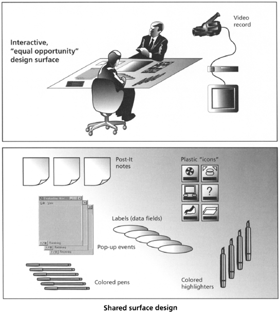
Figure 6.1 Collaborative work setting (top) and design objects (bottom) for the PICTIVE participatory design method (Muller 1991).
A rather different approach is “off-the-shelf” prototyping, where new computer-user situations are approximated with combinations of existing technology (Carroll, Rosson, et al. 1998). For example, a telephone might be used to simulate audio conferencing over the Web, or email folders might be used to simulate a discussion forum. Future users can try out the existing technology to see what it enables in terms of goals and activities; their experiences with these related systems helps them to imagine what a more complete system might provide. Off-the-shelf prototypes can be a relatively inexpensive way to explore usability issues that are hard to appreciate with static materials such as paper and pencil.
6.2 Choosing Among Alternatives
Throughout a project, usability issues that cannot be resolved by discussion or analysis will crop up. If the issue is important, one or more user interface prototypes may be developed to compare alternative solutions. For example, a team designing an online shopping system may be uncertain whether to use conventional Web pages with interactive forms, or a Java applet with a direct-manipulation interface. A direct-manipulation interface is likely to be more engaging and may promote sales. However, a Java-based solution will take longer to develop. Special-purpose prototypes illustrating the two styles could be tested with users to see how much of a difference the user interface makes.
A SunSoft team exploring new-generation user interfaces chose to use video prototyping techniques, because the film medium removes all of the real-world constraints of physical devices, and of input and output processing. At the same time, the team wanted to create a believable 10-year vision. The result was the Starfire video (Tognazzini 1994): Julie, a product manager for an automobile company, must develop a multimedia presentation for an emergency meeting with her CEO. She has five hours to put together a presentation that would normally take a week to prepare. With the help of technology, the report is constructed and delivered smoothly, including a rapid retrieval of just the right information needed to neutralize an attack by a rival product manager.
Tognazzini reflects on seven guidelines his team followed to make this video prototype visionary but at the same believable:
- Carefully question how realistic the interaction techniques will appear (e.g., just pointing at something to retrieve it), and be willing to skim over details that would require too much of a leap into the future.
- Ensure that the vision works, that is, that the actors’ goals are achieved. This means being willing to spend the cash to get things right, or to iterate as much as needed.
- Be sure that something goes wrong in the story, because this is what happens in real life (Julie’s competing manager has a surprise rebuttal).
- Avoid impossible hardware designs, especially for input and output devices.
- Do not eliminate or finesse interaction with computers simply to save money (i.e., it is cheaper to film a video where the actor just talks). Design a believable user interface and then simulate the parts of the interaction that you can afford.
- Emphasize visibility of the simulated user interactions; a scripted video can reveal more about user interaction than normal observation allows.
- Include or explore social as well as technical issues; they are an important part of real life and make the vision more engaging.
Not all user interface prototypes are built for usability testing. Suppose the online shopping team is also debating what feedback to provide during the purchase transaction. They want to include enough that buyers can track their progress through the transaction, but not so much that they are slowed down or irritated (Chapter 5). The problem in this case is that network delays will introduce timing uncertainties into the user interaction, making it hard to predict the response-time effects. To better understand the problem, a prototype could execute a scripted interaction over and over, in many different network contexts. The resulting timing data could then be used to predict the delays users would experience.
Prototypes developed to answer specific questions help to set constraints or boundary conditions on a design solution—a user interface designer decides to use Java instead of HTML, or to provide feedback only after a Submit request, not during the request construction. However, in order to be confident of test results, the prototype and associated test must be realistic (Tradeoff 6.2): If the Java versus HTML prototypes cannot be used for actual tasks, or if they are evaluated by people more sophisticated than the average Web user, the results will be difficult to interpret. If feedback delays are measured in a limited range of network conditions, or if the simulated dialogs are too simplistic, the timing runs will not be representative. As a result, constructing and testing special-purpose prototypes can be quite expensive, taking resources away from other project activities.
Detailed special-purpose prototypes help to answer specific questions about a design, BUT building a meaningful prototype for each issue is expensive.
Scenario-based reasoning and claims analysis can help in deciding what and when to prototype. Scenarios describe representative users engaged in useful or satisfying activities, so they are an implicit source of information about meaningful test conditions. The associated claims analysis points to open issues in the design; discussing the pros and cons may suggest alternatives that should be evaluated.
6.3 Usability Testing
Usability testing is the core of usability engineering practice: Representative users are asked to interact with system prototypes, and their behavior and subjective reactions are studied (Chapter 7). Prototypes can be used to test all aspects of usability for a system—what users will expect when they encounter parts of the system, how they will go about pursuing their goals, how they will respond to system feedback, and what subjective reactions they will have.
The most convenient prototype for usability testing is an early working version of the system. A working system brings a sense of realism to test tasks—the system has sufficient functionality and user interface features that test participants can behave in a relatively natural and unhindered fashion. Task instructions can be minimal, because evaluators can rely on the system to guide users through the test tasks. Issues associated with overall complexity or internal consistency can be examined, and the measures of satisfaction or irritation that are collected will be much more meaningful.
Unfortunately, waiting for a running version of a system may mean that usability testing must be postponed well into the development process (Tradeoff 6.3). A popular alternative is to build a realistic simulation with rapid prototyping tools (e.g., Visual Basic or Macromedia Director), with the understanding that the prototype is temporary and will be replaced eventually by the real system. A discardable prototype can be an excellent option if the usability professionals already have expertise with an appropriate tool, but if not, building the prototype may become a major implementation effort itself. There is also the risk that a prototype will exhibit enough functionality that the team (or its management) comes to believe that what began as a prototype is the final system.
Realistic prototypes increase the validity of user test data, BUT may postpone testing, or require construction of customized (throw-away) prototypes.
Significant user feedback can be collected without an operational system. For example, very early in the design process, a test participant can be given a hypothetical task context, asked to describe his or her initial goal, shown a single display screen, asked for an immediate reaction or interpretation, asked to indicate what action should be taken to pursue the goal, and so on (Carroll & Rosson 1985). The prototype in this case is just a few screens (or even pieces of paper), but it supports collection of valuable information about whether and how the design matches people’s expectations and goals (see “Low-Fidelity Prototyping” sidebar). A scenario machine prototype is similar, but includes enough programming logic to move participants through a predefined sequence of displays (Carroll & Kay 1985).
More complex arrangements may be necessary when the user interface involves novel input and output, or the system provides computational services that are hard to convey with displays or printed materials. In a Wizard of Oz simulation, one or more team members hides in another room. This person observes a user’s input and simulates appropriate output; the simulated output is then displayed as if the computer had generated it (Carroll & Aaronson 1988).
Usability engineers often worry that usability tests conducted on special-purpose prototypes will not provide realistic usability evaluation data. As a result, they may choose to delay their evaluation activities until a running version of the system is available. The problem with this is that the test results may come too late in the overall development cycle to have an impact on design.
Virzi, Sokolov, & Karis (1996) argue that usability evaluation of even very rough (what they term low-fidelity) prototypes can provide useful input to redesign activities. For example, during development of an electronic encyclopedia, these researhers compared test users’ experiences with a low-fidelity prototype and a high-fidelity prototype.
In this case, the low-fidelity prototype was simply a deck of index cards corresponding to screens in the encyclopedia. In contrast, the high-fidelity prototype was a functional electronic book. The interesting result was that test users detected problems of the same sort (e.g., item selection was difficult and function key positioning was inconsistent) and at the same frequency for both prototypes. Although it is impossible to “prove” a hypothesis of no difference, experiments such as this hold great hope for evaluators seeking inexpensive prototyping methods.
At the same time, Virzi, Sokolov, and Karis emphasize that low-fidelity prototypes are not appropriate for all usability testing needs. For example, if a team has usability concerns related to system performance or the aesthetic characteristics of a visual design, a more realistic prototype is necessary for a meaningful test. The following table lists some of the strengths and weaknesses of low-fidelity prototyping discussed by these researchers.
Advantages and disadvantages of low-fidelity prototypes in usability testing
| Advantages | Disadvantages |
| Faster to create and iterate | Cannot test performance issues |
| Costs less, smaller impact on resource planning | Cannot assess detailed aesthetic or flow issues |
| Smaller investment, minimizes resistance to change | Will not engage client or marketing personnel |
| Demands fewer special skills, increases participation | Cannot be used to guide documentation team |
| Flexible format, can be customized to situation | Developers may be dismissive or confused |
| Can be constructed at any point in the process | Scales poorly to large or complex issues |
A challenge for Wizard of Oz prototyping is that the “wizard” must behave according to rules that match the actual capabilities, accuracy, and errors of the computer. For example, in Maulsby, Greenberg, and Mander (1993), the wizard attended only to natural language segments that were part of a predefined language model. Depending on the complexity of the service being simulated, considerable preparation and training may be required. The speed with which humans can process and generate information is also an issue—a Wizard of Oz prototype will not be effective for tasks where response time and accuracy are crucial to perceived usability.
Other options include prototypes that present all of the intended functionality of a system, but only at the top level (sometimes called a horizontal prototype). For example, a participant may be able to initiate an online shopping order, but not complete it. This can be useful in studying people’s high-level goals and action plans. Alternatively, the prototype may implement one or two tasks in full detail (sometimes called a vertical prototype); this is most useful when a few tasks are seen as particularly complex or central to the design. If a system has considerable functionality, but little or no error detection, it might be evaluated as a chauffered prototype—a well-trained assistant accepts and executes requests on behalf of the actual test participant.
6.4 Evolutionary Development
In some projects, user interface prototypes are a natural byproduct of the overall development process. Evolutionary development is an approach to software design and development that moves through analysis, design, development, and testing in a tightly interleaved and incremental fashion. Working prototypes are built as soon as possible in the project, evaluated in some fashion, and the results immediately applied to guide changes. A working version of the system is always available, but is also always being updated to reflect the most recent set of tests and design enhancements.
An evolutionary development process is particularly suitable for exploratory projects, where a team has an open-ended mission and few if any business or pragmatic constraints. In such projects, the first prototype is likely to be small in scope, as the team searches for direction. As ideas are explored and accepted, more functionality is added in an incremental fashion.
Evolutionary methods can be used in more structured projects as well, as long as a series of incremental steps is planned in advance. For example, an e-commerce project plan may include services for buyers, sales personnel, and management. But the team may decide to first prototype the buying functionality, and then add in separate services for the other stakeholders. This simplifies the software development process and enables evaluation of the most business-critical services (i.e., purchasing) first.
The incremental and evolutionary approach to system development has become very popular in recent years, due partially to the explosion of Web-based information services and the accompanying pragmatics of developing systems in “Web time” (Chapter 10). Now that virtually anyone can prototype and publish a flashy Web page over a weekend, the pressure to quickly develop new and intriguing network applications, or to add new features to existing services, is a strong nonfunctional requirement. High-level software technology such as HTML and XML support rapid development; software engineers are developing methods designed to produce systems quickly but also with a high degree of accuracy (Beck 1999).
If a prototype is built as soon as an idea is proposed, feedback about its usefulness and feasibility can be obtained immediately. However, there are disadvantages to doing this (Tradeoff 6.4). If the idea is a good one (and sometimes even if it is not!), the team will accept it and proceed to refine and elaborate. In so doing, they discard other possibilities, or fail to even take the time to search for other ideas. This is the problem of local optimization. Refining an acceptable idea may produce a satisfactory solution, but it may eliminate the analysis, reconceptualization, and radical transformation that could produce an excellent solution.
Iterative refinement of an implementation enables continual testing and feedback, BUT may discourage consideration of radical transformations.
A related problem is the implicit impact of the code developed during evolutionary development. Suppose a prototype is found to be unacceptable from a user interface perspective (the shopping interactions are extended and awkward), but its basic services are working (the customer does eventually end up with a purchase). If considerable effort has been spent on developing a prototype, it may be very difficult to discard it and redesign the problematic interaction sequences. Teams working under time pressure will find it very painful to follow Fred Brooks’s advice to “plan to throw one away,” even if they have built a deliberately small and incomplete version.
The decision to discard or radically transform an evolutionary prototype depends to a great extent on the culture and mission of the development group. A team with flexible resources and a commitment to excellence is much more likely make major changes. But such decisions also depend on the software technology in use. For example, a dynamic language such as Smalltalk is designed for rapid iteration and change. Program code can be modified while software is executing; features are typically implemented in a modular fashion so that the rest of the system continues to work as before.
Constant change and iteration are not appropriate for all evolutionary development projects, however. In large and complex projects, it may be necessary to decompose a system into components that are developed by different groups and later integrated. Safety- or security-critical applications typically require careful documentation and monitoring throughout development. Development settings such as these should use a staged process, with each incremental refinement planned and agreed to in advance.
Even for exploratory development projects, constant iteration and change can be dangerous. If there is no overall software architecture in place that constrains the changes made to the code, the software system can quickly become complex, hard to understand, and thus difficult to maintain (Tradeoff 6.5). For systems built to serve a short-term purpose, this may be acceptable, but software that will be maintained and enhanced over time needs a coherent and extensible design (Meyer 1988).
6.5 Science Fair Case Study: Prototyping
User interface prototypes are developed for many different purposes throughout system development. Prototyping is a key element of iterative design—design ideas are made concrete in a prototype, evaluated (Chapter 7), and modified through redesign.
In SBD, prototypes are built in parallel with writing scenarios. A scenario describes how features of a system contribute to the users’ experience; a prototype is a preliminary implementation of a system or its features. However, this does not imply a 1:1 correspondence between scenarios and prototypes. Often only a few features in a scenario are prototyped. Or a prototype may implement features from multiple scenarios; indeed, it may demonstrate features not yet described in a narrative. In general, a prototype is more refined than a scenario, simply because a prototype must take a position on physical details (shape, color, positioning, and so on) that need not be specified in a narrative.
In the science fair project, we created prototypes for a number of purposes. Early in the project, prototypes were used to explore individual design scenarios. The goal was to illustrate what the system might look like at a point in time, or during a short sequence of events. At various points in design, special-purpose prototypes were built to investigate specific usability concerns. Throughout the project, the system itself was developed in an evolutionary fashion within the MOOsburg software framework.
6.5.1 Scenario Mock-ups
The VSF project is a case study in participatory development, in which students, teachers, and community members contributed to activity and interaction design. Many of the participatory sessions used scenario mock-ups, which are sketches or drawings created to illustrate the functionality of one or more scenarios. In many cases, these were hand-drawn sketches (Figures 4.16 and 4.17) shared and discussed as we stepped through the actions of a scenario. The felt board used in the participatory design sessions (Figure 4.19) is another example of a scenario mock-up. Mock-ups are often created for novel input or output devices (e.g., a camera, a large wall display), or even for an entire work setting (e.g., an assembly line or a newspaper layout room). The roughness of these prototypes conveys that the design ideas are tentative and that wide-ranging input is needed.
On occasion, mock-ups were created to illustrate a graphic design in a more refined fashion. Figure 6.2 is a science fair screen mocked up in Microsoft PowerPoint; it was built to suggest what Sally’s exhibit looked like when first opened by Alicia and Delia. A mock-up like this requires more effort to create than the sketches in Chapter 4, and is used to support more detailed evaluation goals. When we created this, we had already developed an activity design for the scenario and were beginning to work out the details of information and interaction design. Our discussions focused on issues such as the miniaturized windows in the lower right, whether the function of these icons would be recognizable, whether the visitor list and chat log were in effective positions, whether color coding participants would be helpful in following the text chat, and so on.
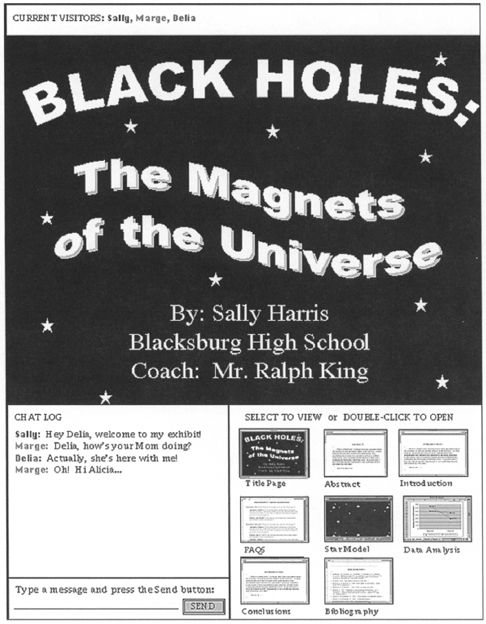
Figure 6.3 presents yet another scenario mock-up; this one was developed by a professional artist using Adobe Photoshop. This is not a scenario from the science fair project; it represents the “Marissa” design scenario written for the Virtual School project described in Chapter 1 (Carroll, Chin, et al. 2000). In this case, the mock-up was created for marketing purposes (we needed to convey a vision for project investors), and thus, visual refinement and appeal were high priorities.

Figure 6.3 A scenario mock-up developed by a professional artist. The source scenario for this mock-up comes from the Virtual School project described in Chapter 1 (Figure 1.2).
6.5.2 Scenario Machines
A set of screen drawings or images can be used to simulate the flow of a scenario—the evaluators simply step through a series of screen images much like children use flip cards to animate a cartoon. But this can be quite tedious and requires manual intervention. Thus, interaction design issues are often demonstrated or explored with a scenario machine, a software prototype that implements one or more scenarios.
A scenario machine gives a sense of how the overall system will work by demonstrating one or more activities in depth. This approach is sometimes called a vertical prototype, because it builds a relatively complete version of just one part of a system. It can be contrasted with a horizontal prototype, which would include screens for all (or many) functions in a system but elaborate none of the details.
Like any prototype, scenario machines can be built at many levels of quality, with a corresponding variation in production cost. Table 6.2 lists some of the tools commonly used to build user interface prototypes, along with a brief indication of strengths and weaknesses. The simplest approach is to create a computerized version of the cartoonist’s flip cards—a sequential set of screens where pressing a button or link on one screen leads to the next. This effect is easy to do in a language like HTML, especially when graphical editing tools such as Macromedia Dreamweaver are available for constructing the pages and links. One problem is that realistic interactions (e.g., processing and responding to a user’s input) are difficult to simulate in this paradigm. HTML is also quite limited in its support of display elements and layout procedures.
Table 6.2 Several common user interface prototyping tools, with contrasting strengths and weaknesses.
Sample Tool Hypertext Markup Language |
Strengths Declarative tag-based code Many examples available over the Web Runs on different platforms using common Web browsers Graphical editors such as Dreamweaver |
Weaknesses Limited user interface display elements and layout options User input restricted to link navigation and text input Processing of text input requires programming in Perl or similar language |
Macromedia Director |
Flexible support for many visual effects, animation, etc. Easy to simulate mouse-based direct manipulation Simple frame-by-frame script controls temporal behavior |
Can be tedious to create and position many individual elements Emphasis is on display and animation rather than on user input and data processing |
| Microsoft Visual Basic |
Extensive library of user interface display and control widgets Drag-and-drop visual editor to create and position visual elements and attach event handlers Good interface with databases and other programming tools |
Constrained by existing widgets unless willing to develop new components Code quickly becomes complex and difficult to maintain Requires programming skills |
An alternative is to use a multimedia animation environment such as Macromedia Director. This environment offers much more flexibility and support in defining, positioning, and controlling visual and auditory elements. However, tools such as this are designed to convey a visual impression, not to accept, process, and respond to user input. A visual programming environment (e.g., Microsoft Visual Basic) raises many more possibilities for accepting and processing user input, while simplifying some aspects of prototype development (e.g., creating and positioning user interface controls). But despite the graphical development environment, a language like Visual Basic requires programming skills for effective use.
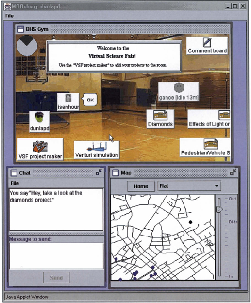
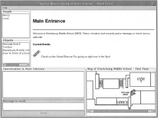
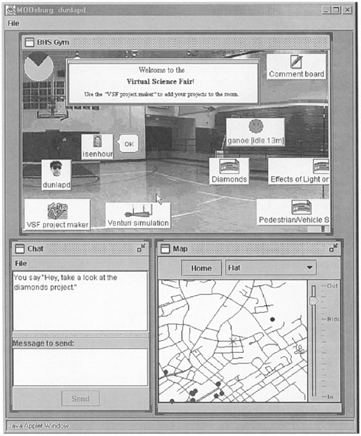
Figure 6.4 shows a prototype from a science-fair visit scenario, built early in the project in Hypertext Markup Language (HTML). In this scenario, Lucas arrives at the fair, greets Nancy who is already there, and goes with her to the exhibit area in the GYM. If a user clicks on the circle in the GYM area of the floor plan, the upper right frame updates to show a view of the exhibits. If a tool in the objects list is clicked, a second browser is launched to show the tool, and so on. In other words, this “prototype” consists simply of a series of HTML screens organized into frames, with links that can be used to play out a scenario script.
The increasing use of the Web for business, home, and leisure applications has made HTML a popular prototyping language. As a declarative tag language, it is simple to learn; a number of graphical editors are also available for creating HTML code automatically. Another attractive feature is that an HTML prototype can be put on a server and demonstrated virtually anywhere in the world. This was important to us because many of our participatory design sessions took place out in the community (e.g., at the schools and the senior center). However, the user interaction in HTML prototypes is restricted to the simple logic of hyperlinks. Creating dynamic Web pages (e.g., pages that respond in a situation-specific fashion based on user input) requires more conventional programming tools.
Later in the project, we built more sophisticated scenario machines using the Macromedia Director environment. This required somewhat more effort than writing and interconnecting HTML pages, but it also gave us many more options for visual effects, such as dynamic feedback that was based on mouse activity. It is also relatively easy to work with individual user interface controls in this environment. Text, images, or other user interface objects can simply be dragged to any position, whereas in HTML it can take significant effort to set up a table as a grid for positioning elements, particularly when they are sized or shaped differently.
Macromedia Director was originally designed for graphical artists and film industry professionals, but has been adopted by many usability engineers as a prototyping tool for visual direct-manipulation interfaces. Nilson Neuschotz (2000) provides an excellent introduction to this tool, using a simple online store as an example.
The tool provides a visual construction environment built around a film metaphor (Figure 6.5). A multimedia system is composed of “cast members” (upper left window). Cast members may be visual objects (e.g., icons or buttons) or they may be behaviors that are assigned to visual objects (e.g., change appearance when the mouse pointer is on top of an icon). Visual cast members are often created with external graphical editors and imported; behaviors are composed from a set of common events and actions (middle left window). For example, an icon might change to one shape when the mouse pointer moves over it, to another when the mouse button is clicked, and so on.
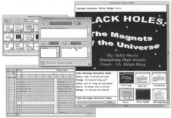
The resulting prototype (called a “movie”) is organized into “scenes,” which take place on a “stage” (the large window on the right). The scene is enacted under the control of a “script” (lower left), which is simply a time-ordered set of frames. Any logic needed for moving among scenes must be defined as behaviors. The center window in Figure 6.5 shows a behavior that causes the prototype to jump from the “Start” scene to the “Star Model” scene if the mouse is clicked on the miniature of the star model.
Figure 6.5 shows just a small portion of the cast members and behaviors needed to implement an entire scenario (this one is based on Alicia and Delia’s visit). For example, only one behavior for the Star Model miniature is visible, and only a few scenes have been created. But even this abbreviated view shows how the number of elements and relationships can quickly become complex.
Code development per se is minimal, which makes Macromedia Director attractive to nonprogrammers wanting to build visual prototypes with some degree of interactivity. The current version includes support for downloading information from Web pages; this means that a prototype can retrieve and respond to data created and maintained by other systems. However, this highly visual programming paradigm does not scale well for systems that use a large set of interactive elements. In the science fair project, most of our prototyping was done in the Java framework built to support MOOsburg (Isenhour, Rosson, & Carroll, in press).
We used scenario machines primarily as visual aids for participatory design discussions. The goal was to illustrate and envision the hypothetical actors’ experiences. Note, though, that a prototype of this sort can also be used for more conventional usability evaluation: Instead of bringing a group of stakeholders together to view and discuss a prototype, we could have asked them to enact a specific scenario, and then observed their expectations, actions, and reactions. These findings could then have been used to refine the scenarios and prototypes (Chapter 7).
6.5.3 Prototyping Alternatives
Because the science fair is an application within MOOsburg, we already had a functioning software system that we could use to prototype alternative design proposals. This does not mean that it is easy to build multiple versions of the entire science fair design, but rather that we can easily construct simple prototypes that contrast two or three specific design ideas. Indeed, the philosophy behind MOOsburg is that its users should be able to design and implement their own places in the community network.
One of the tools MOOsburg provides for this is a background editor. This is a specialized version of an electronic whiteboard that is used to create and refine the image used as “wallpaper” at a MOOsburg location. Figure 6.6 shows the background editor being used to create a background for the main view of the science fair. A panoramic image was created by taking a number of exposures at different angles from the center of the high school gymnasium; the set of exposures was then stitched together with a digital camera utility program. The result was imported into the background editor, where we could manipulate its size and add additional information (e.g., the Welcome sign).

Figure 6.6 The background editor tool built into MOOsburg supports the importing of JPEG or GIF files in combination with simple graphical editing functions. The option “Opaque objects” is selected if the room designer wishes objects held in this room to have a white bounding box around them (see Figure 6.8).
The next two screen shots illustrate a simple experiment we then carried out with this science fair view. During information design, we became concerned about users’ ability to perceive other visitors and objects “in front” of a background. Depending on the background and on the number of objects, the overall view can become crowded and visually complex.
We explored two alternative presentations. The first alternative (Figure 6.7) places each image directly on the background. In the second presentation (Figure 6.8), the objects are “opaque” (the bounding box around the object is filled with white). The two screen shots bring out the design tradeoff between simplifying perception (the opaque objects are easier to detect and interpret) and improving visual appearance (they look awkward and unrealistic). Based on a small amount of usability testing, the MOOsburg developers decided that people building rooms should be allowed to choose either of these two display options. The choice of option seems to depends on several variables, such as the number of items in the room, the darkness of the background image, and the likely goals of the visitors.

Figure 6.7 One prototype of the science fair exhibit space, where each visitor or object is merely presented “in front” of the background.
6.5.4 Evolutionary Development
MOOsburg is a distributed client-server system built in Java (Figure 6.9). It consists of an object database holding a persistent software representation of every place, person, or object in the system. The database is stored on a central server, a networked machine that provides copies or descriptions of these objects on request. The server also applies and broadcasts updates to the objects so that all users in MOOsburg interact with the same objects. Requests to the server are made by client software that is executed on each user’s workstation. When MOOsburg developers define a new object (e.g., a special message board), they make it available to others through a “machine” that creates instances of the new object.
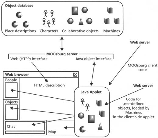
The MOOsburg user interface is supported by a toolkit written in Java (the Content Object Replication Kit, or CORK; Isenhour, Rosson, & Carroll, in press). Java is an object-oriented language, and the MOOsburg software takes advantage of the abstraction and inheritance capabilities of the Java language. All science fair objects (the exhibit space, individual exhibits, and visitors) are implemented as subclasses (specializations) of a general-purpose class called BasicObject. This general-purpose class defines the behavior shared by all objects in the virtual environment: what it means to be created, named, positioned, moved, and so on. Objects that are used collaboratively (e.g., two people at an exhibit) are subclasses of a second abstract class that can process multiple input streams and broadcast resulting updates. Abstract classes such as these simplify the creation of new object types and user interface controls.
The object-oriented architecture of MOOsburg has been a critical enabler of evolutionary development in the science fair project. We can make small changes or enhancements with little effort, and can retract or revise these modifications without a major software redesign. If we did not have a coherent and extensible software framework, changes to the database or to the user interface would be made in an ad hoc fashion, producing unexpected side effects and making it difficult for new developers to understand or maintain the code.
Figure 6.10 demonstrates how MOOsburg classes were used to implement the opaque-object experiment. The figure lists the three central classes used in presenting the view of a place: a Landmark is a content object that simply holds the view of the object (its WhiteBoardContent) and a list of things currently there (people and other objects). A WhiteBoardContent includes a pointer to an image file (if relevant), a list of graphical shapes created, and two Boolean variables that can be either True or False. This is where the opaqueness option was inserted; the second Boolean variable specifies whether the image is panoramic.
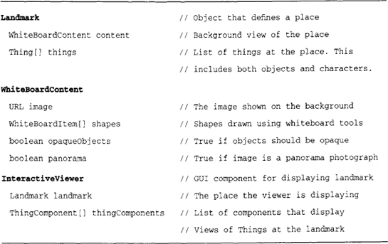
An Interactiveviewer manages the actual display and manipulation of a background view. But it delegates much of the work to its Landmark, which in turn delegates the work to its own WhiteBoardContent. Similarly, the display of the people and objects in the room is delegated to the components responsible for each type of object. This sort of decomposition and delegation is standard in object-oriented design, and provides the flexibility to modify and extend one class without revising code in associated classes.
At the same time, an evolutionary prototyping approach to software development has its own costs. The MOOsburg team has now invested considerable effort in the client-server architecture diagrammed in Figure 6.9, and in building classes such as those summarized in Figure 6.10. Radical changes or extensions to science fair functionality (e.g., objects that are indexed by age or category as well as place) would require a relatively large redevelopment effort. As a result, major refinements of this sort are likely to be ignored, or at best explored in a more limited way with special-purpose prototypes.
Summary and Review
This chapter has explored goals and techniques for building user interface prototypes. An important responsibility of usability engineers is choosing the right approach as a function of the goals and resources of the prototyping effort. Prototyping activities in the science fair project were used to exemplify different approaches to and goals for creating user interface prototypes. Central points to remember include:
- Even very early in a project, sophisticated prototypes can be built using video or computer animations. These create excitement for a project, but if not presented carefully may cause misinterpretation or premature commitment.
- Very rough prototypes (e.g., paper and pencil) can be quite effective in opening up the design space, encouraging analysis and design ideas by diverse stakeholders.
- When used to choose among design alternatives, a prototype should be as realistic as possible, to ensure that the data on which the decision is based will be a valid indicator of what would happen in the real world.
- Usability testing can begin very early in project development, as soon as ideas can be sketched on paper or using a graphics editor.
- The types of usability data that are meaningful depend on the fidelity of the prototype. With low-fidelity prototypes, users can react to screens and make predictions about functionality or controls, but data such as performance times and aesthetic judgments should be obtained with working system prototypes.
- An incremental development process yields ongoing access to prototypes. But because each prototype is a working system version, significant changes to function or user interface may be costly.
Exercises
- Reread the vignette at the beginning of the chapter. How could a better outcome have been produced? Offer at least two specific suggestions that you believe would have improved the situation. Provide a rationale for each one.
- Look over the scenario describing Alicia and Delia’s visit in Chapter 5 (Figure 5.6). Compare it to the scenario mock-up in Figure 6.2. Make a list of the things that the scenario conveys, but that the screen image does not convey, and vice versa.
- Develop a set of index cards that could serve as a storyboard for the scenario of Mr. King coaching Sally. On each card, sketch a state of the screen, and then on the back indicate what Mr. King does that moves it to the next state. When you are done, step through the cards with a friend not familiar with the scenario. Is your friend able to follow what is happening? Discuss what you might do to enrich the experience.
- The mock-up in Figure 6.2 was created in Microsoft PowerPoint. Create a similar mock-up using an HTML editor. After you are done, discuss the construction process—what was hard to do; what was easy; whether you think this is a good tool for a mock-up of this sort; and why or why not.
Project Ideas
Develop a prototype of your online shopping scenarios:
- Discuss the use of different prototyping methods and what each would contribute to your project; write a prototyping proposal that includes the rationale for the approach you decide to take.
- Implement the prototype.
- Discuss what you have learned by creating the prototype, how your design has been elaborated, and what feedback you are now in a position to obtain.
Recommended Readings
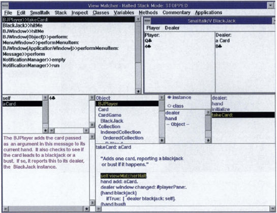
Plate 7 The View Matcher for learning Smalltalk coordinates five different views of an example application: The application view (upper right), the code view (lower right), the explanation view (lower left), the object inspector view (middle left), and the message stack view (upper left).

Plate 8 A scenario mock-up developed by a professional artist. The source scenario for this mock-up comes from the Virtual School project described in Chapter 1.

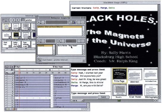

Plate 11 Sample virtual reality applications: (top) VRML model of a space capsule floating on water, and (right) a molecular structure inside a CAVE.