Chapter 4
Basic Types
The use of types is fundamental to the understanding of VHDL, especially when used for logic synthesis. Furthermore, an understanding of types is necessary to understand the later chapters. For these reasons, this chapter has been placed very close to the beginning of the book.
VHDL is referred to as a strongly typed language. This means that every data flow (input, output, internal signal etc.) has a type associated with it and that there can never be any ambiguity about what type a data flow is.
A feature of VHDL that newcomers sometimes struggle with is that the specific implementation of an operator is selected by the type of the signals used. So to add two numbers together you always use the+operator, but the implementation will be different depending on the type of the operands: an integer adder will be used if the operands are integers, a fixed-point adder will be used if the operands are fixed-point and so on. So, if you get the types right, you will get the operations you want. If you confuse your types, you will get into trouble.
There are a few built-in types that are part of the language, but the language also has the capability of defining additional types. Many of the types in common use in logic synthesis are additional types.
This chapter will cover the built-in types and the basic type handling of VHDL. Chapter 6 will cover the additional logical and numerical types added specifically for use in synthesis and which will be used for nearly all signals in a real design.
There are eight classes of types in VHDL, but not all of them are synthesisable. Table 4.1 shows which of the classes of type are commonly synthesisable.
Table 4.1 Synthesisable types.
| Class | Synthesisable |
| enumeration types | yes |
| integer types | yes |
| floating-point types | no |
| physical types | no |
| array types | yes |
| record types | yes |
| access types | no |
| file types | no |
The four classes of type that are not synthesisable will not be covered in this book. The four classes that are synthesisable will be covered in the following sections.
A number of types are predefined in the language. The predefined types are to be found in a package called standard that must be a part of every VHDL system. Package standard is listed in Appendix A.1 for reference.
Table 4.2 lists the type definitions to be found in package standard, the class each type belongs to and whether it is supported by synthesis.
Table 4.2 Standard types.
| Type | Class | Synthesisable |
| boolean | enumeration type | yes |
| bit | enumeration type | yes |
| character | enumeration type | yes |
| severity_level | enumeration type | no |
| integer | integer type | yes |
| natural | subtype of integer | yes |
| positive | subtype of integer | yes |
| real | floating-point type | no |
| time | physical type | no |
| string | array of character | yes |
| bit_vector | array of bit | yes |
The type severity_level has been marked as unsynthesisable because, although as an enumeration type it is technically synthesisable, it should never be used in this way.
The usage and interpretation of all of the synthesisable types will be covered in the rest of this chapter.
Values, signals and variables (which will be covered in Section 8.3) of a type can be combined in expressions using operators. For example, to find the logical and of two signals of type bit, the and operator would be used. There is a comprehensive set of operators in VHDL, which will be introduced here briefly, but covered in much more detail in Chapter 5.
For the purposes of this book, the operators will be divided into 5 groups. These groups, and the relevant detail section of Chapter 5 are: boolean (Section 5.3), comparison (Section 5.4), shifting (Section 5.5), arithmetic (Section 5.6) and concatenation (Section 5.7):;
| boolean: | not, and, or, nand, nor, xor, xnor |
| comparison: | =,/=, <, <=, >, >= |
| shifting: | sll, srl, sla, sra, rol, ror |
| arithmetic: | sign +, sign -, abs, +, -, ∗,/, mod, rem, ∗∗ |
| concatenation: | & |
Each group of operators can only be applied to a particular set of types. As each type is introduced in the following sections, the groups of operators applicable to it will be listed.
Type bit is the built-in logical type. Bit has two values, represented by the characters '0' and '1'. In other words the type definition is:
type bit is ('0', '1'),
This is a kind of type known as an enumeration type. The quotes (notice that they are single quotes) are essential. This is because the values are characters, not numbers and in VHDL, characters are distinguished by enclosing them in single quotes. Enumeration types with character values are also known as character types.
The operators that apply to type bit are:
| boolean: | not, and, or, nand, nor, xor, xnor |
| comparison: | =,/=, <, <=, >, >= |
Bit has the full set of boolean operators. The boolean operators give a result that is also of type bit. This means that boolean operators can be combined in complex expressions and all the intermediate results are of type bit.
Bit has the full set of comparison operators, all of which give a boolean result. It is possible to test a bit signal for a value, but the result of the test is boolean and not bit. For example:
if a = b then
This tests if the value of bit signal a is the same as the value of bit signal b. The result will be true or false: boolean values. The boolean type will be covered in detail in the next section.
4.4.1 Synthesis Interpretation
Type bit is represented by a single wire, with the value '0' represented by logic 0 and the value '1' by logic 1. Logical operators are implemented directly, with each signal one bit wide.
In practice, bit is very rarely used since the two logic levels are insufficient for any but the most trivial of examples. Typically, at least four logic levels are required so that unknown and tristate values can be modelled. In practice, the nine-value type std_logic is usually used instead of bit. Type std_logic will be covered in Chapter 6.
Type boolean is the built-in comparison type for VHDL. That is, the results of comparisons are of type boolean. It is very rarely used directly as a logical type, since type std_logic fills this role.
The boolean type is predefined and has the following definition:
type boolean is (false, true);
This means that boolean is an enumeration type that has only two values, false and true.
The operators that apply to type boolean are:
| boolean: | not, and, or, nand, nor, xor, xnor |
| comparison: | =,/=, <, <=, >, >= |
Boolean is usually used indirectly whenever a comparison between two values of any other type are made.
To illustrate this, consider the following example:
if a = 0 and b = 1 then
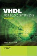
For this example, assume that a and b are 4-bit integers. Each of the comparisons is implemented as a comparator. The result of each comparison is a boolean, which is implemented as a single wire. The results are then combined using the and operator for type boolean. The resultant circuit is shown in Figure 4.1.
Figure 4.1 Using boolean as a comparison result.

The result of the test, in this case a test for equality, is a boolean value. Boolean will be the result regardless of the types of a and b.
Boolean itself has the full set of six comparisons. That is, two boolean signals can be compared using any one of the six comparisons listed earlier. However, these aren't of much use and usually only the boolean operators are used.
4.5.1 Synthesis Interpretation
Boolean has two values: false and true. When boolean signals are mapped onto hardware by a synthesiser, they are represented by a single wire. The boolean value false is represented by a logic 0 and the value true by a logic 1.
Note that it is not possible to use any other type than boolean in a comparison. In particular, you cannot use a signal of type std_logic or bit in a conditional test. Since most logical signals are modelled by std_logic, it is therefore necessary to convert the signal to type boolean. This conversion is most easily carried out by using the equality or inequality tests. For example:
if s = '1' then
In this case, the std_logic signal s is being converted to boolean by simply testing for the '1' value. The result will be true when s is equal to '1' and false otherwise. This is a fairly crude type conversion, because there are eight other values in the type std_logic, all of which are treated as false, including the weak high value 'H'.
In synthesis, this is not important, since only three of the nine values of std_logic have synthesis interpretations anyway. These three values are the logical values '0' and '1', and the high impedance value 'Z'. The last of these is only used in describing tristate drivers, so in all other situations there are only two valid values.
It is important when dealing with integers to distinguish between the type called integer and defined in the standard, and any other integer types that are user-defined. Throughout the text, the phrase ‘type integer’ refers to the built-in type called integer, whereas the phrase ‘integer type' refers to any type that has integral values.
4.6.1 Type Integer
Type integer is the built-in numeric type that, as its name suggests, represents integral values.
The range of values covered by integer is not exactly defined by the VHDL standard, but must be at least the range −2147483647 to +2147483647. This is the range for 32-bit 1's-complement or sign-magnitude representations of numbers. It is a slightly smaller range than that covered by 2's-complement representation. The reason for specifying the reduced 1's-complement range as the standard is not clear but is presumably to allow VHDL tool vendors some freedom in the choice of representation since it does allow for a sign-magnitude implementation. In practice, all implementations of the language use 32-bit 2's-complement integers with a lowest value of −2147483648. It is safe to assume this slightly broader range.
The definition of type integer is therefore:
type integer is range −2147483648 to +2147483647;
The set of operators usable with type integer are the full set of comparison operators and the full set of arithmetic operators.
| comparison: | =,/=, <, <=, >, >= |
| arithmetic: | sign +, sign -, abs, +, -, ∗,/, mod, rem, ∗∗ |
There are restrictions on the use of the ∗∗ operator for synthesis – this will be covered in Section 5.6.
4.6.2 User-Defined Integers
In addition to the built-in type integer, it is possible to define other integer types. For example, if it is known that all calculations are to be performed in 8-bit arithmetic, an 8-bit integer type could be defined for those calculations. However, the use of user-defined integer types is not recommended, indeed it is strongly discouraged, and this section describes them for reference in case they are used in an existing design.
The only limitation on user-defined integer types is that they can have ranges n∗o greater than the range of the built-in type integer. The built-in integer effectively defines the implementation limit for numeric types. This means that user-defined integers are limited to 32 bits.
An example of an integer type definition that defines a new type with an 8-bit 2's-complement range is:
type short is range -128 to 127;
In integer expressions, it is not possible to mix different integer types. For example, it is not possible to mix type integer and type short in the same expression. This clear division between different types is what is referred to as strong typing. It is claimed to be a very useful feature of the language since it allows a lot of errors to be discovered at an early stage in a design cycle. If an attempt is made to mix types inappropriately, it will result in an error. Strong typing promotes careful use of types with a clear understanding of which type is used to convey which information.
Having said this, it is not good practice to define a lot of unique types for each signal in a design. This is one of the most common pitfalls with new users of VHDL, who think that, because it is possible to define many distinct types, that this is a good idea. Inevitably, signals of different types will meet somewhere in the design. This then requires type conversions between types that tend to confuse and obscure the meaning. In practice there are very few errors that are trapped by the use of user-defined integer types, yet they can cause enormous frustration due to the strong typing. This is why it is strongly recommended that the built-in type integer is regarded as the only integer type.
Furthermore, the synthesis types described in Chapter 6 are the preferred types for defining numeric data, so in fact it is recommended to only use integer types to control for loops (Section 8.7) or index arrays (Section 4.10). They should not be used as datapath types.
The rules of VHDL insist that the result of an integer calculation must be within the range of the type. Thus, if you were using the type short, all expressions using short would have to give values in the range −128 to 127. If a calculation exceeds the range of the type, an error will occur during simulation. If this happens the result of the calculation is undefined and most simulators will stop the simulation at this point. The choice of integer range must be made with this in mind – VHDL integers do not wrap round on overflow. Again, the synthesis types described in Chapter 6 do not have this problem.
When an integer type is defined, VHDL automatically provides the following operators for the new type:
| comparison | =,/=, <, <=, >, >= |
| arithmetic | sign +, sign −, abs, +, −, ∗,/, mod, rem, ∗∗ |
These operators will be interpreted for synthesis in exactly the same way and with the same limitations as for the standard type integer.
4.6.3 Integer Subtypes
A subtype is a restricted range of a type. The type a subtype is based on is known as its basetype.
For example, there is a predefined subtype of integer that is called natural and a second called positive. The definitions of these types are:
subtype natural is integer range 0 to integer'high;
subtype positive is integer range 1 to integer'high;
The value integer'high represents the highest value of type integer. Bear in mind that type integer is implementation defined but that this value is almost certainly +2147483647.
A signal declared to be of subtype natural is in fact an integer, but with restricted usage. All the operators that the type integer has are inherited by its subtypes. Furthermore, when type natural is used in calculations, the calculations are carried out using the basetype, integer, and then checked to ensure that they fit the subtype range of natural. This check is not carried out until an assignment is made.
The significance of this interpretation of subtypes is that intermediate values in an expression can exceed the subtype range, provided that they do not exceed the basetype range and provided the final value of the source expression is within the subtype range of the assignment target.
For example, start with the following definition of a 4-bit subtype of integer:
subtype nat4 is natural range 0 to 15;
Note how this creates a subtype of natural, itself a subtype of integer. There is no special significance in this subtype of a subtype: nat4 is still just a subtype of integer.
Take four signals w, x, y and z of subtype nat4, related by the assignment:
w <= x − y + z;
Consider the case where the three source signals have the following values:
x = 3
y = 4
z = 5
The subtraction 3–4 is carried out first, giving an intermediate value of −1. Since the intermediate values of the expression are calculated using the basetype integer, this is a valid value. This value is then added to 5 to give the final result of 4. This value is then assigned to the target w, and is checked to ensure that it is within the range of nat4, which it is.
This contrasts with the same expression using a user-defined integer basetype with no negative values. In that case, the initial subtraction would exceed the range of the basetype and therefore cause an error.
4.6.4 Synthesis Interpretation
The synthesis interpretation of integers relies on the assumption that simulation has been carried out and that there are no simulation errors. This, completely reasonable, assumption allows simplifications to be made that give smallest-possible circuits for each operator. The particular rules that are used to optimise the mapping onto hardware are:
- intermediate values are within the range of the basetype of the expression;
- the value assigned to the target is in the range of the subtype of the target.
In addition, knowledge of the behaviour of arithmetic also provides some optimisations.
An integer type or subtype is represented by a bus of wires, with the number of wires in the bus depending on the range of the subtype. The number of wires will be the number of bits required to represent all the values of the subtype range.
Furthermore, the representation will be a 2's-complement if the range of the calculation includes negative numbers, but will be simply an unsigned magnitude if the calculation range does not include negative numbers.
It is not always made exactly clear where unsigned arithmetic will be used by the synthesiser, another reason to use the synthesis types instead, but generally if a calculation is made using an unsigned subtype and the result is immediately assigned to an unsigned target, then a synthesiser can infer that an unsigned circuit can be used. If the calculation is more complicated and there are intermediate values in the calculation (as in the example above), then the synthesiser must use signed representation for the intermediate values to allow for the fact that those intermediate values can be negative.
Consider again the following assignment that does contain intermediate values:
w <= x - y + z;
This can be written with parentheses:
w <= (x - y) + z;
This means that the subtraction takes place first, resulting in an intermediate value. Since this intermediate value can be negative, a signed representation must be used, even though an unsigned subtype is being used throughout. The addition must also be signed because one of its inputs (the output of the subtracter) is signed. Finally, the assignment to the unsigned signal w causes a conversion from the signed intermediate value to the unsigned result. This conversion is done by simply dropping the sign bit.
The representation of integer types always includes zero, even if the range itself does not. There is no optimisation of the implementation to suit an offset range.
For example, consider the following type:
type offset is range 14 to 15;
Even though this type has only two values, it will be represented by a 4-bit bus because this is the number of bits required to represent the maximum value, 15, as an unsigned integer.
Similarly, the 2's-complement representation of signed numbers means that the implementation will always be (almost) symmetrical around zero. There are no optimisations for offset ranges, nor for entirely negative ranges. The number of bits used to represent the type is the maximum of the number of bits required to represent the most negative and the most positive values of the type using a 2's-complement representation.
For example:
type negative is range −2147483648 to −1;
This type is a 32-bit type, even though it only has half the values of the full 32-bit range.
In practice, most integer subtypes used in circuit design will either be zero-based unsigned types or symmetrical signed types.
Another issue is the number of bits used to represent the intermediate values in an expression.
Looking again at the assignment:
w <= x - y + z;
All four signals w, x, y and z are 4-bit unsigned numbers. But what size is the intermediate value from the calculation x − y? In principle, since the intermediate value is calculated using the basetype, the intermediate value should be the size of the basetype. For subtypes of type integer this would make all intermediate values 32-bits. However, this clumsy solution is optimised in practice by using knowledge of the behaviour of computer arithmetic.
First, the earlier argument showed that the calculation will use signed representation, so the two unsigned 4-bit values x and y will have to be converted to 5-bit signed values by adding a sign bit. We know that the largest result from subtracting two 5-bit signed numbers is a 6-bit value, so in fact the intermediate value is represented as a 6-bit signed number. This is then added to signal z, which must first be converted from 4-bit unsigned to 5-bit signed. The addition gives a 7-bit signed intermediate result. The assignment to w results in truncation of the result and conversion back to an unsigned representation by discarding the sign. This truncation reduces the result to 4-bits since w is a 4-bit number. The truncation is done by discarding the most significant bits. This data flow is illustrated by Figure 4.2.
Figure 4.2 Intermediate value precisions.

The gradual expansion of the word length in an expression like this allows for the fact that intermediate values are allowed to exceed the range of the subtype, provided that they stay within the range of the basetype. This also puts an upper limit on the expansion: the largest intermediate value representation will be 32-bits when using integer subtypes. The truncation by discarding the most significant bits is valid because this corresponds to the point where a simulator would check the value to ensure that it was within the target subtype. If there are no simulation errors, then allowing the synthesiser to discard the extra bits cannot affect the value.
An enumeration type is a type composed of a set of literal values. The most obvious example that illustrates an enumeration type is the state variable of a state machine. The literal values are names, so the type can be thought of as a set of names.
For example, here is an enumeration type that might be used for a traffic-light controller:
type state is (main_green, main_yellow, farm_green, farm_yellow);
This type has four literals, identified by the names main_green, main_yellow, farm_green and farm_yellow. Any names can be used as literals except the reserved words of the VHDL language (for example, type would be illegal as a literal).
Enumeration types can also be defined using character literals. Such enumeration types are referred to as character types. There are advantages in using character types, especially when using arrays, because VHDL provides some short cuts for defining arrays of characters. For this reason, most logic types are defined as character types. The specific details of the special characteristics of character arrays will be covered in Section 4.10.
As an example, a four-value logic type could be defined as follows:
type mvl4 is ('X', '0', '1', 'Z'),
As always in VHDL, character literals are enclosed in single quotes. The characters that can be used as literals are all those that are found in the standard 8-bit ISO 8859-1 or Latin-1 character set, which contains 256 characters and incorporates ASCII as its first 128 values.
There is also a predefined character type called character (don't get confused between the general term character type and the specific type that happens to be called character). Type character contains the complete 8-bit Latin-1 character set, in other words all of the possible character literals. This can be used for synthesising hardware that is intended to manipulate text provided that the given encoding is the required one – in other words provided that ASCII or Latin-1 encoding is required.
In theory, an enumeration type can contain a mixture of character and name literals. In practice, this is very rarely done and most enumeration types will be pure character types or pure named literal types. One exception is the type character itself, which uses named literals to represent the control characters which would otherwise be impossible to represent. For example, the literal HT (without quotes) is the horizontal tab character.
Two predefined enumeration types have already been described. These are the types boolean and bit. Their type definitions are:
type boolean is (false, true);
type bit is ('0' '1'),
Boolean has named literals, whilst bit has character literals.
The literals of an enumeration type are said to have a position number associated with them, with the first literal having the position 0 and subsequent literals having subsequent numbers. For example, the position numbers of the state type defined above are:
main_green = 0
main_yellow = 1
farm_green = 2
farm_yellow = 3
The position numbers of type character are the numeric codes for the character set. For example:
'A' = 65
'a' = 97
'0' = 48
The position numbers are used by synthesis to implement the type as an unsigned integer.
However – and anyone who has ever used the programming language ‘C’ take special note – enumeration types are not just integer types and the position values cannot be substituted for the literal values. Furthermore, it is not possible to perform arithmetic on enumeration types. Finally, the position values are predetermined by the language definition and therefore cannot be user-defined.
The best way to think of enumeration types is as sets of abstract values, the appropriate use of which makes any VHDL more readable and easy to understand.
The only operators predefined for an enumeration type are the six comparison operators:
| comparison: | =,/=, <, <=, >, >= |
The comparison operators are defined in terms of the position values of the literals. This means that the first (or left) literal in the type is regarded as the smallest – zero – value and the last (or right) as the largest.
The enumeration types boolean and bit are special in that they also have logical operators defined, but this is not generally true and user-defined enumeration types will not have predefined boolean operators. However, it is possible to define your own logical operators using a mechanism called operator overloading. This will be covered in Section 11.3.
A multi-valued logic type is a logic type that includes what are known as metalogical values. These are values that do not exist in the real world but that are a useful concept for simulation. A classic example is the high-impedance 'Z' value. It would not be possible to attach a voltage meter to a circuit and measure a 'Z', but nevertheless the value is well understood and commonly used in the modelling of tristate buses. In a sense, all logic values are metalogical values. The values '0' and '1' do not exist, but they do have a real interpretation as voltages. It is the other values of a multi-valued logic type that are commonly referred to as the metalogical values of the type.
A multi-valued logic type could in principle be represented by any type, such as an integer type, with enough values to cover the full set of values being simulated. However, synthesisers restrict logic types to be one of a predefined set. In fact, most synthesisers will only allow std_ulogic (Chapter 6) to be used as a multi-value logic type, although some still have support for other types for historical reasons, which should all be considered obsolete. There really is no reason to use any other multi-valued logic type.
The concept of a multi-valued logic type is specific to synthesis, since in simulation terms a multi-valued logic type is just an enumeration type like any other.
A synthesiser needs to be able to identify multi-valued logic types so that they can be represented by a single wire, rather than a bus of wires representing the enumeration encoding of all the metalogical values as unsigned integers. A synthesiser usually recognises a multi-valued logic type by knowledge built-in to the synthesiser.
The use of multi-valued logic types for synthesis is full of potential pitfalls. The majority of them fall into the category of using metalogical values as if they were real values, for example, assigning a metalogical value such as the weak driving value 'L' or an unknown 'X' to a signal. Synthesis will either treat these as errors (the safest interpretation) or map them onto one of the two real values (the most dangerous interpretation). This quite arbitrary mapping may result in a subtle change in the behaviour of the circuit.
The safest rule in using multi-valued logic types for synthesis is to use them as if they were type bit. That is, not to refer to the metalogical values at all. There is no legitimate use for the metalogical values in synthesisable models, with the sole exception of the high-impedance value 'Z' that is used in tristates (see Section 12.1).
A record is a collection of elements, each of which can be of any constrained type or subtype. The only unconstrained types, which cannot be used in a record, are unconstrained arrays, which will be covered in more detail in the next section. Unfortunately, unconstrained arrays are the most commonly used and indeed the most useful types, so this constraint makes records very limited in their use. However, they are covered here in case they prove useful.
A record is declared as follows:
type pair is record
first : integer;
second : integer;
end record;
Once a record type has been declared, signals can be declared to be of that type in the same way as with any other type:
signal a, b, c : pair;
A signal of a record type is effectively a collection of signals, one for each element. The rules for the interpretation of each element are the rules for that element's type. For the example of type pair above, the elements are two 32-bit integer types.
The only operations that can be performed on the whole of records are equality and inequality:
| comparison: | =,/= |
These are implemented as element by element comparisons, using the appropriate comparison for the element type. The element equalities are then anded together to form the overall equality. In other words, two record signals are equal if their corresponding elements are all equal.
To access an element of a record, a dot notation is used. For example, to assign the value 0 to the first part of signal a:
a.first <= 0;
The type of a.first is integer, because integer is the type of element first of type pair. All the integer operators can be used on the first element.
To assign values to all the elements of a record requires a notation called an aggregate. An aggregate is a collection of values.
An example of an aggregate is:
a <= (first => 0, second => 0);
This is the full form of the aggregate, using named association, in which each element is explicitly named and associated with a value. The symbol "=>" is known as finger and associates the following value with the named element of the record.
A shorter form of the aggregate uses positional notation. That is, the values of the elements are simply listed in the same order as the elements are defined in the type definition:
a <= (0, 0);
The aggregate can also be used to combine signals (rather than values) together to assign them to a record. For example, suppose there are two signals c and d that are of type integer and they are to be assigned to the pair signal a. This is done as a single aggregate assignment:
a <= (first => c, second => d);
The reverse can also be done, by using an aggregate as the target of the assignment.
For example, the integer signals c and d can be assigned from pair signal a in one assignment:
(c, d) <= a;
In this example, the signals c and d have been bundled together in an aggregate. This aggregated value is than assigned the value of the signal a using a whole-record assignment. The overall effect is the same as the following two separate assignments:
c <= a.first;
d <= a.second;
An array is a collection of elements, all of which are of the same type. The elements are accessed by an index as opposed to a name as with records. The index can be of any integer or enumeration type. It is usually an integer type; in fact it is usually subtype natural so that indices cannot be negative.
An array type can be unconstrained or constrained. An unconstrained array type is one in which the size of the array is as yet unspecified. The type of the index is given but its range is not. It effectively defines a family of array subtypes with the same element type but with a variety of ranges. A constrained array type is one in which both the index type and its range are given. All signals of a constrained array type have the same range.
In fact, constrained arrays are implemented in VHDL as subtypes of an anonymous unconstrained array type. An anonymous type is one with no name, which cannot therefore be used by the user, but exists as a convenience for the analyser. In that sense, all array types in VHDL are unconstrained. However, because the anonymous unconstrained basetype cannot be referred to, it is impossible to use it directly and so only the constrained subtype can be used. Apart from this restriction, there is no other difference in the handling of unconstrained and constrained array types. The following discussion therefore only covers the use of unconstrained array types.
For synthesis, all datapaths must be constrained when they are declared. The reason they must be constrained is that they must be mapped onto hardware. A type maps onto a bus of wires. The datapath must be constrained so that the number of wires in the bus can be calculated.
The requirement that all datapaths are constrained means that either a constrained array type or subtype must be used, or an unconstrained array type combined with a range constraint in the declaration of the signal must be used. In practice, most array types used in synthesis are unconstrained and the signal is constrained in the signal declaration itself.
For example, there is a built-in type called bit_vector, defined in package standard, which defines an unconstrained array of type bit. The definition of this type is:
type bit_vector is array (natural range <>) of bit;
The symbol "<>" is known as box and signifies an unconstrained array range. The rest of the index type declaration shows that the range must be within the range of subtype natural, so no negative indices will be allowed.
In use, signals of this type are constrained in the signal declaration:
signal a : bit_vector(3 downto 0);
This defines a signal with four elements, indexed by the range 3 downto 0. This is called a descending range; it means that the first (left) element is element number 3, the second element 2 and so on down to the last (right) element that is numbered 0.
Arrays may be constrained with either an ascending range or a descending range for the index. The index values are simply values of subtype natural.
A descending range is the common convention for arrays representing buses, especially if they are bitwise representations of integers. The convention makes the m.s.b the leftmost bit and gives it the highest index. It is also part of the convention to make the l.s.b, which is the rightmost bit, have the index zero.
Note that this is just a convention, and ascending ranges could be used without changing the meaning of the model. However, most engineers already use this convention, so conforming with it will make the model much easier to understand and so is recommended best-practice.
An alternative way of achieving the same effect is to declare a constrained subtype of the unconstrained array, and then to declare the signal to be of this subtype. The equivalent declarations to give the signal the same characteristics as the signal declaration above are:
subtype bv4 is bit_vector (3 downto 0);
signal a : bv4;
Every signal that is defined in terms of bit_vector or any of its subtypes is of basetype bit_vector. These subtypes can be of any size. Therefore, since the basetype is always the same, signals of different sizes can be mixed in expressions. However, it is required that when an array is assigned to another array, the two arrays are of the same size, although they can have different ranges.
When a signal assignment is made with array signals, the assignment is made element by element from left to right without reference to the ranges of the arrays.
For example, consider the following two signals with different ranges:
signal up : bit_vector (1 to 4);
signal down : bit_vector (4 downto 1);
The assignment of one signal to the other is legal, since they are the same basetype and the same length, even though their actual ranges are different:
down <= up;
Since the assignments are made element by element from left to right, this is equivalent to:
up(1) <= down(4);
up(2) <= down(3);
up(3) <= down(2);
up(4) <= down(1);
Notice that it is the position of the element in an array, not its index that determines the outcome of the assignment. There is plenty of scope for pitfalls here.
This example also shows that the range doesn't have to begin or end at zero just because the index subtype is natural. Any range in which all the possible indices fall within the range of natural can be used.
Elements of the array can either be accessed using actual index values (static indexing), or by using a signal of the appropriate index type (dynamic indexing).
An example of static indexing is:
a(0) <= '1';
Since signal a is a bit_vector – that is, an array of type bit – the elements are of type bit and have all the operators appropriate to the type. This is generally true for all arrays – the elements can be manipulated individually using the operators for the element type.
For example:
z(0) <= (a(0) and b(0)) or (c(0) and d(0));
If a signal is to be used to access an array by dynamic indexing, then the indexing signal can be defined with either an ascending or a descending range regardless of the range of the array. The array is accessed by the value of the index, not its relative position in the type definition. A descending range integer type could be used for the indexing signal. However, it is strongly recommended that only ascending ranges are used with integer types and that, furthermore, only subtypes of integer are used for array indices.
Thus, to define a signal to index the array:
signal item : integer range 0 to 3;
The array can be dynamically indexed with this signal:
a(item) <= '0';
Indexing allows access to the elements of an array one at a time. It is also possible to access a subrange of an array as a whole. This is done using a slice. For example:
b(1 downto 0) <= a(3 downto 2);
This example demonstrates the use of slices as both the source of the assignment and as the target. Both slices must be of the same size for the assignment to be legal. To be synthesisable, the slice must have a constant range; dynamic slices are not allowed. The type of a slice is the same as the type of the signal being sliced. For example, a slice of a bit_vector is a bit_vector.
4.10.1 Array Operators
The only operators available for all array types are the comparison operators and the concatenation operator.
| comparison: | =,/=, <, <=, >, >= |
| concatenation: | & |
However, for any array of type boolean or of type bit, the logical operators and the shifting operators are also predefined. Furthermore these operators have been added to std_logic_vector (see Chapter 6):
| boolean: | not, and, or, nand, nor, xor, xnor |
| shifting: | sll, srl, sla, sra, rol, ror |
The details of how these operators work is left until the relevant sections of the next chapter (Chapter 5). This section will just deal with the types used in the operators.
The comparison operators take two arrays of the same type and return a result of type boolean. The standard interpretation of these comparisons is unusual and not as would be expected for a bus representing an integer value (see Section 5.4). Fortunately, the standard synthesis packages (see Chapter 6) provide more sensible comparisons that correspond to a numerical interpretation of the type.
The concatenation operators allow an array to be built up out of smaller arrays and elements. For example, a 16-bit bit_vector can be built from two 8-bit bit_vector signals by concatenating them:
signal a, b : bit_vector(7 downto 0);
signal z : bit_vector(15 downto 0);
...
z <= a & b;
The result of the concatenation is the same type as the arguments – in this case bit_vector.
Similarly, single elements can be concatenated with an array to make a larger array. A common requirement is to convert an unsigned representation into a signed representation by adding a zero sign bit to the left end of the bus. In this case the buses are represented by the types in numeric_std, even though that type has not been covered yet (see Chapter 6). There are two tasks – adding the sign bit and converting the type. The example shows the conversion of a 7-bit unsigned to an 8-bit signed:
signal a : unsigned (6 downto 0);
signal z : signed (7 downto 0);
...
z <= signed('0' & a);
The concatenation creates an array of the same type as the array argument – in this case the signal a is of type unsigned, so the result of the concatenation is the same type. The whole expression is therefore wrapped up in a type conversion to convert it into type signed. Without the type conversion, the assignment would be illegal because it is not possible to assign an expression of one type to a signal of another type.
The boolean operators are similar to their corresponding single-bit operators. When a boolean operator is applied to an array, each element of the array is processed separately from left to right. So for example, to form the and of two buses, each element of one bus is combined with the corresponding element of the other bus, in left to right (not numerical) order to form a result of the same size. Both arrays must be the same size:
signal a, b, z : bit_vector (7 downto 0);
...
z <= a and b;
Finally, the shift operators shift an array by a distance specified by an integer argument, the shift distance. For example, to perform a logical shift left by two bits, the following example would be used. The result of the shift is an array of the same size as the array being shifted:
signal a, z : bit_vector (7 downto 0);
...
z <= a sll 2;
4.11 Aggregates, Strings and Bit-Strings
Array values can be created from a set of element values using aggregates:
a <= (3 => '1', 2 => '0', 1 => '0', 0 => '0'),
The type of the aggregate is deduced by the analyser from the type of the target. In this case, the aggregate is of type bit_vector. The range constraint is worked out from the set of indices used within the aggregate except where the context gives some clues as is the case here where the assignment to signal a gives the expected range. For the assignment to be legal, the indices must fit within the index type (natural in this case), they must be contiguous (no gaps in the indices) and the lengths of the arrays must be the same.
To make this absolutely clear, this assignment is equivalent to the following four assignments:
a(3) <= '1';
a(2) <= '0';
a(1) <= '0';
a(0) <= '0';
The rules for calculating the range of aggregates can be confusing and has scope for pitfalls in the use of aggregates for arrays. To avoid problems, it is strongly recommended that aggregates are given exactly the same range as the target and in the same direction as was done in the example above.
It is possible to use aggregates to bundle together signals, rather than values, of the element type to create an array and to assign them all together in an array assignment. For example, given four signals of type bit called elem0 - elem3, then they can be assigned to signal a in one assignment:
a <= (3 => elem3, 2 => elem2, 1 => elem1, 0 = > elem0);
The reverse can also be done; that is, aggregates can be used as the target of an assignment:
(3 => elem3, 2 => elem2, 1 => elem1, 0 => elem0) <= a;
There are a number of alternative ways to represent array aggregates. All of the following assignments are exactly equivalent to the first aggregate example above.
The first alternative notation is to group indices together in a multiple-choice selection:
a <= (3 => '1', 2|1|0 => '0'),
Once again, it is good practice to preserve the ordering of the target to avoid ambiguity.
The second example uses subrange selection to assign the same value to a subrange of the array:
a <= (3 => '1', 2 downto 0 = > '0'),
Here, also, the range of the target has been preserved by using a descending range in the subrange selection.
The final example uses the others selector:
a <= (3 => '1', others => '0'),
The others choice must be the last choice in the aggregate and selects all the remaining elements of the target.
All of the notations so far have been named notations. This means that the indices have been explicitly named and associated using the finger "=>") with a value. In addition to the named notations, array aggregates can use positional notation.
The same example in positional notation is:
a <= ('1', '0', '0', '0'),
Because array assignment is carried out from left to right according to position, the value '1' will be assigned to the leftmost element of a, in this case element 3, and so on. This is usually clearer than the named association and is the preferred form. The only exception to this is the special case of assigning the same value to all elements using only an others clause:
a <= (others => '0'),
This can only be done by named association, but remember that the range of the others clause is taken from the range of the target.
This notation cannot be used where the range is unknown. A common example is in a conditional test:
if a = (others => '0') then
This is illegal, because the range of the aggregate cannot be deduced from the context. The equality operator can take arrays of any size for each argument, so the size of a on the left cannot be used to deduce the size of the right operand. The others clause can only generally be used in assignments where the size can be deduced.
This can be rewritten to use a range attribute:
if a = (a'range => '0') then
For arrays of integers and named enumeration types, this is the full set of notations available. However, arrays of character types have two further notations that are extremely useful short-cuts and are used almost universally for assigning values to character arrays such as bit_vector and std_logic_vector (Chapter 6). The first of these notations is the string literal:
a <= "1000";
This is not only simpler, but much clearer than the other notations. It is a positional notation, so the elements are assigned from left to right, just as with the positional aggregate.
The alternative string notation is known as a bit-string literal:. This notation allows more flexibility in the representation of values, such as using underscores to divide values into groups and the options of binary, octal or hexadecimal notation. A bit-string literal is distinguished from a string literal by a prefix of B, O or X, which can be lowercase or uppercase, representing the use of binary, octal or hexadecimal within the bit-string. The extended values 10–15 in the hexadecimal notation are represented by the characters A–F, which may also be lowercase or uppercase. Examples are:
x <= B"0000_0000_1111";
x <= O"00_17";
x <= X"00F";
These all assign the same value (15) to signal x.
One limitation with the octal and hexadecimal notations is that they can only be used to assign to arrays that are a multiple of 3 or 4 bits long, respectively. The binary representation is equivalent to the ordinary string literal except that it may also include underscores to separate the bits into convenient groups. This is not possible for ordinary string literals.
Bit-string literals are available to all character array types that contain the literal values of '0' and '1'. The octal and hexadecimal values are converted into their binary string literal equivalents using the character values '0' and '1' and then the resulting string is assigned to the target.
Attributes are a mechanism for eliciting information from a type or from the values of a type. They are useful, for example, in finding the left and right values in a type or in finding the positional value of an enumeration literal. In some circumstances it is good practice to use an attribute to refer to a value instead of the value itself, so that if the values of the type change later due to a design change, the reference will change in line with the redesign.
There are a number of attributes that apply to integer and enumeration types and another set, often with the same names, which apply to array values. To keep their meanings clear, they will be discussed as two completely separate sets of attributes.
4.12.1 Integer and Enumeration Types
This section will discuss the following attributes and their application to scalar types – that is, integer and enumeration types. All these attributes are predefined for all such scalar types:
type'left
type'right
type'high
type'low
type'pred(value)
type'succ(value)
type'leftof(value)
type'rightof(value)
type'pos(value)
type'val(value)
To illustrate this section, the following three types will be used:
type state is (main_green, main_yellow, farm_green, farm_yellow);
type short is range -128 to 127;
type backward is range 127 downto -128;
The reverse range integer type backward has been included for illustration, even though it is strongly recommended that descending range integers are never used.
The leftmost and rightmost values of a type can be found using the left and right attributes:
state'left = main_green
state'right = farm_yellow
short'left = -128
short'right = 127 backward'left = 127
backward'right = -128
It is also possible to find the lowest and highest values of a type using the low and high attributes. These are subtly different from the left and right values of a type, as can be seen from the results on the reverse range type:
state'low = main_green
state'high = farm_yellow
short'low = -128
short'high = 127
backward'low = -128
backward'high = 127
In other words, the low value is the left value for an ascending range and the right value for a descending range.
The two attributes pos and val convert an enumeration value into the integer representing its position number and vice versa. These attributes also work on an integer type, where the position value of the integer is the same as its actual value, so the feature is not very useful. The attributes take a single argument, which is the value to be converted. The value can be either a constant or a signal, in the latter case the attributes effectively perform type-conversion functions between integer types and enumeration types.
state'pos(main_green) = 0
state'val(3) = farm_yellow
The integer value returned from the pos attribute is of a type known as universal integer. Universal integer is not a type that can be explicitly used but is a convenience for the analyser, since universal integers can be assigned to any integer type. This means that the value returned from the pos attribute can be assigned to any integer type. Similarly, the argument of the val attribute is universal integer, so can come from any integer type.
For example:
signal state1, state2 : state;
signal short1, short2 : short;
...
short1 <= state'val (short2);
state2 <= state'pos (state1);
In this example, the two types in use are short, which is an enumeration type, and state, which is an enumeration type. Type conversion is not possible for this combination of types. The pos and val attributes give us a way of performing an equivalent operation. In the first assignment, the value of signal state1, of type state, is being converted into its positional value. Since this positional value is a universal integer, it can then be assigned to any integer type, in this case to type short. In the second assignment, the reverse process is taking place. The value of signal short2, of integer type short, is being used as the argument to the val attribute. This attribute can take any integer type as an argument and converts the value into the equivalent enumeration value of type state. This value can then be assigned to the signal state2.
Finally, there is a set of four attributes that can be used to increment or to decrement a value. These are the succ, pred, leftof and rightof attributes. The succ attribute finds the successor of its argument; that is, the next highest value of the type, regardless of whether the type is ascending or descending. The pred attribute finds the predecessor value; the opposite of succ. The leftof attribute finds the next value to the left of its argument; this will be the next lowest value for an ascending range and the next highest for a descending range. Finally, the rightof attribute finds the next value to the right of its argument; the opposite of leftof.
For example:
state'succ(main_green) = main_yellow
short'pred(0) = -1
short'leftof(0) = -1
backward'pred(0) = -1
backward'leftof(0) = 1
These attributes can be used as incrementers and decrementers if used with a signal rather than a literal value as their argument. However, beware that they do not wrap around on overflow. In other words:
state'succ(farm_yellow) = error
4.12.2 Array Attributes
Array attributes are used to elicit information on the size, range and indexing of an array value. These attributes are far more widely used than the other type attributes and many applications for them will be seen in the rest of the book. It is generally considered good practice to use attributes to refer to the size or range of an array signal. In this way, if the size of the array is changed due to a design change, the VHDL statements that access the array will automatically adjust to the new size. Furthermore, in the case of for loop statements (Section 8.7) and for generate statements (Section 10.6), attributes are the only way to specify that elements are visited in a left to right order, regardless of whether they have an ascending or a descending index range: a common requirement. Further discussion of these applications will be left for the relevant sections.
This section will discuss the following attributes:
signal'left
signal'right
signal'low
signal'high
signal'range
signal'reverse_range
signal'length
Notice that these attributes act on an array signal, not a type like the attributes in the previous section. In principle, they can also be used on a constrained array subtype. This usage is less common in practice.
To illustrate this section, the following two signal declarations will be used:
signal up : bit_vector (0 to 3);
signal down : bit_vector (3 downto 0);
The left attribute returns the index of the leftmost element of the array, whilst the right attribute returns the index of the rightmost element. The low attribute returns the index of the lowest numbered element of the array; this is the leftmost for an ascending range and the rightmost for a descending range. Similarly, the high attribute returns the index of the highest numbered element.
For example:
up'left = 0
down'left = 3
up'right = 3
down'right = 0
up'low = 0
down'low = 0
up'high = 3
down'high = 3
All of these attributes return a value of the index type of the array. This means that they can be used to access the array directly. For example, suppose that the signal down was representing a signed number, using the common interpretation that the leftmost element is the m.s.b. and therefore represents the sign bit. If there is a signal of type bit that is to be assigned the value of the sign of down, then it would be done using the following signal assignment:
sign <= down(down'left);
The range and reverse_range attributes are mainly used in controlling for loops and for generate statements and will be discussed in more detail in Sections 8.7 and 10.6 respectively. They can also be used to define the subtype of a signal. They return the range constraint of an array signal. This is not a value that can be assigned to a signal because there is no way of declaring a signal that takes a range value. However, they can be used wherever an array range is used.
For example:
signal a : bit_vector (3 downto 0);
signal b : bit_vector (a'range);
In this example, the second signal b has been defined to have the same range as signal a. This can be a safe way of working since, if the design changes such that the size of signal a changes, then signal b will automatically adjust to the same size.
In the above example, the range attribute gave the value 3 downto 0. The reverse_ range attribute literally reverses the range, so that the value in this example would be 0 to 3.
Finally, the length attribute returns the number of elements in an array. This value is a universal integer and so can be assigned to any integer signal. A common use of this attribute is in the normalisation of a signal. For example, given a signal with an unconventional index range:
signal c : bit_vector (13 to 24);
Then it is possible to create another signal of the same size as c, but normalised to the common convention of a descending range ending in zero:
signal d : bit_vector (c'length-1 downto 0);
It is now possible to assign the first signal to the second since they are the same size:
d <= c;
This normalisation is used extensively in VHDL, especially when writing subprograms, as discussed in Chapter 11.
4.13 More on Selected Signal Assignments
This section is effectively a continuation of Section 3.9. It covers the use of selected signal assignments with the types covered in this chapter.
Consider the problem of converting the traffic-light controller type, introduced earlier, into control signals for individual lights.
The traffic-light controller enumeration type was:
type state is (main_green, main_yellow, farm_green, farm_yellow);
The control signals for the individual lights will be represented by a std_logic_vector with three elements, the first for the red light, the second for the yellow and the third for the green. The encoding will reflect the UK traffic-light conventions.
The signal declarations are:
signal current_state : state;
signal main_lights : bit_vector (0 to 2);
The selected signal assignment to decode the current state is:
with current_state select
main_lights <= "001" when main_green,
"010" when main_yellow,
"100" when farm_green,
"110" when farm_yellow;
The synthesis interpretation of this is a single multi-way multiplexer, as shown in Figure 4.3. The exact implementation of this multiplexer may vary slightly from synthesiser to synthesiser but the behaviour will always be the same. In this case, the control condition is an enumeration type, so this will also be converted into its synthesis representation to give a two-bit control bus.
Figure 4.3 Multi-way selected signal assignment.
As well as using a single value to match with, known as the choice, for each branch of the assignment, it is possible to specify multiple choices, range choices and to use an others choice to mop-up any remaining selections not already covered. The formats for these multiple choices are the same as the multiple choices used with aggregates.
The following example shows how these various multiple choices are used. It shows how the control signals of the lights example above could be individually encoded in separate selected signal assignments.
with current_state select
main_lights(0) <= '1' when farm_green to farm_yellow,
'0' when main_green to main_yellow;
with current_state select
main_lights(1) <= '1' when main_yellow | farm_yellow,
'0' when main_green | farm_green;
with current_state select
main_lights(2) <= '1' when main_green,
'0' when others;
It is generally good practice to end with a when others choice to mop up the remainder. It is a requirement of the VHDL language that all possible values are covered and this is the easiest way to guarantee it. However, as the first two assignments in the example shows, it is not essential to finish with an others choice.
The selection condition can be an array signal. For example, to do the reverse conversion from the light controls back to the state type, the following selected signal assignment can be used:
with main_lights select
current_state <= main_green when "001",
main_yellow when "010",
farm_green when "100",
farm_yellow when others;
Note that the others choice in this selected assignment is not equivalent to a choice of ‘110'. The 3-bit bit_vector has 8 possible values, since each element can have any one of the two values of bit, but only 4 of them have legal interpretations in this example, since there are only four combinations of lights. The remaining 4 selections are unused and should never occur in this design. Nevertheless, all of these must be covered by the choices to make the selected signal assignment complete. In this example, all the unused encodings of the light controls have been mopped up into the selection for farm_yellow by using the others choice.