Chapter 5
Operators
The VHDL language has a set of standard operators that can be used to perform comparisons, form boolean equations and perform arithmetic. This set of operators is the toolkit that is used to build up RTL models.
This chapter introduces the built-in operators and what they do, with an explanation of the rules that VHDL uses to decide the order of precedence when calculating a complicated expression.
The full set of operators in VHDL is listed here:
| not | inversion |
| and | and function |
| nand | not-and function |
| or | or function |
| nor | not-or function |
| xor | exclusive-or function (bitwise inequality) |
| xnor | exclusive-nor function (bitwise equality) |
| = | equality |
| /= | inequality |
| >= | greater-than or equal |
| > | greater-than |
| <= | less-than or equal |
| < | less-than |
| sll | shift-left logical |
| srl | shift-right logical |
| sla | shift-left arithmetic |
| sra | shift-right arithmetic |
| rol | rotate left |
| ror | rotate right |
| + | addition |
| − | subtraction |
| + | plus sign |
| − | minus sign |
| ∗ | multiplication |
| / | division |
| mod | modulo arithmetic |
| rem | remainder after division |
| ∗∗ | exponentiation |
| abs | absolute value |
| & | concatenation. |
Operators are classified by the standard as logical, relational, adding, sign, multiplying and miscellaneous. The reason for classifying the operators is to allow for operator precedence. This is not the same classification I have used in the rest of the book, which is simpler and groups operators by what they do, rather than their precedence order. However, this section is about the precedence rules and so is based on the formal classification given by the VHDL standard.
The precedence of operators is the order in which they will be processed in an expression.
For example, in the expression:
3 + 4 * 5
This is interpreted as:
3 + (4 * 5)
and not as:
(3 + 4) * 5
The result is 23, not 35. The multiplication is carried out first because multiplication in arithmetic has a higher precedence than addition.
If an expression has operators of the same precedence, they are processed from left to right.
For example:
3 - 4 + 5
The result is 4, because subtraction and addition have the same precedence and so the expression is interpreted from left to right as:
(3 - 4) + 5
and not as:
3 - (4 + 5)
The classification of the standard operators defines their precedence. The classifications are listed here in order of precedence, with the highest first:
| miscellaneous: | ∗∗, abs, not |
| multiplying: | ∗,/, mod, rem |
| sign: | +, - |
| adding: | +, -, & |
| shift: | sll, srl, sla, sra, rol, ror |
| relational: | =,/=, <, <=, >, >= |
| logical: | and, or, nand, nor, xor, xnor |
The rules for operators in VHDL are a bit odd. Generally, they are more restrictive than you would expect from using other languages, so you end up with more parentheses than are strictly necessary, but within those restrictions VHDL on the whole follows the rules of arithmetic precedence. Unfortunately, there are some exceptions to this which may become pitfalls if you are not careful.
This description will be based on the syntax rules defined in the VHDL Language Reference Manual [IEEE-1076, 2008].
I have generally avoided any mention of syntax in this book, but this is really the best way to describe the operator precedence rules. If you cannot bring yourself to read syntax, skip to the next section!
Here then, is the syntax for operators from the VHDL LRM, starting with the overall definition, an expression:
expression ::=
relation { and relation } | relation { or relation } |
relation { xor relation } | relation { xnor relation } |
relation [nand relation] | relation [nor relation
]
These rules have a number of consequences:
logical operators are the lowest precedence
Logical operators are evaluated after the rest of the expression (the relations).
logical operators have the same precedence
All the binary logical operators are at the same level in the syntax – the bottom, so therefore they must all have the same precedence. This is unusual in that in some other languages and is considered the same precedence as multiplication and or the same as addition. Not in VHDL!
it is impossible to mix logical operators
Once you have used an operator, all subsequent relations must be combined using the same operator – for example:
a and b or c
is illegal and would result in an error. This restriction is included to resolve confusion caused by giving all logical operators the same precedence.
you must use parentheses a lot
Since logical operators cannot be mixed at the same level of an expression, parentheses must be used. For example:
a and b or c
is illegal, so it must be written:
(a and b) or c
nand and nor cannot be chained
By this I mean that the expression:
a nand b nand c
is illegal (note the use of square [] brackets rather than curly {} braces in the syntax). This restriction was incorporated into VHDL because it was felt that people might not realise that this example is not the result of nanding a, b and c together because the nand operator is not associative. In other words:
y <= (a nand b) nand c
is not the same as:
y <= a nand (b nand c)
To avoid the potential for error due to this non-associative behaviour, VHDL insists on the use of brackets to break up the inverting operators into two-way functions only.
The non-inverting operators (including xor) are associative and so can be chained together to form expressions of any length.
As you can see, VHDL logical operators are not as you would expect. Note that the unary operator not has not been dealt with yet – it is the exception to the above rules and will be dealt with later since it is classed as a miscellaneous operator.
The next level of syntax is the relation:
relation ::=
shift_expression [relational_operator shift_expression]
relational_operator ::=
= | /= | < | <= | >| >=
This appears more normal, although it is again restrictive compared with other languages because you cannot chain comparisons. For example, you cannot say
if a > b = false then ...
since this is an error. This is bad style anyway, but most languages would at least allow it.
This also shows that logical operators are evaluated after comparisons, so the test
if a = '1' and b = '0' then ...
is evaluated exactly as expected, as
if (a = '1') and (b = '0') then ...
So there are no surprises there.
The next level of syntax is the shift_expression:
shift_expression ::=
simple_expression [shift_operator simple_expression]
shift_operator ::=
sll | srl | sla | sra | rol | ror
The rules here are very similar to the above relation operators. You cannot chain shift expressions. For example, you cannot say:
a sll 2 srl 2
to strip off the leftmost two bits of a bus, since this is an error. You would have to use parentheses again to achieve this effect.
Note that shifts are evaluated before relations, so the expression
if a sll 2 > 5 then ...
is evaluated as
if (a sll 2) > 5 then ...
as expected.
The next level of syntax is the simple_expression:
simple_expression ::=
[sign] term { adding_operator term }
sign ::=
+ | -
adding_operator ::=
+ | - | &
These rules are again somewhat unusual. In particular, you cannot have a sign operator before a term except for the first one. In other words
a + -b
is an error and parentheses are needed again. Also, strangely, the abs operator is not classed as a sign operator and will be dealt with later. It will be seen that this creates some peculiar side effects.
The sign operator is evaluated before the adding operators, so only the first term is negated by the negation operator. In other words,
-a + b
is interpreted as
(-a) + b
The next level of syntax is the term:
term ::=
factor {multiplying_operator factor }
multiplying_operator ::=
* | / | mod | rem
This is what would be expected for normal arithmetic. Multiplying operators have a higher precedence than adding operators so are evaluated first. This means that
a + b * c
is evaluated as
a + (b * c)
as you would expect.
The interaction between multiplication and sign operators bears closer examination. Since multiplication operators have higher precedence than sign operators,
-a * b
is interpreted as
-(a * b)
This is quite different to the way that sign operators work with addition, which was shown earlier. Of course, this makes no difference to multiplication, since the negation of the result is the same as negating one of the arguments before multiplying, but it can make a difference with the other operators such as mod that do not have this symmetry.
The most likely problems with modulo and negation are due to the fact that
-a mod b
is actually interpreted as
-(a mod b)
and not, as you might expect
(-a) mod b
Modulo is not symmetrical around zero, so this could give a different result to that expected. For example, given:
a = 3b = 4
then the expected result might be:
(-a) mod b = 1
whereas the actual result will be:
-(a mod b) = -3
The next level of syntax is the factor:
factor ::=
primary [** primary] | abs primary | not primary
This is the highest level of precedence in VHDL, since the primary is any object (signal, variable, array element, etc.) that is appropriate for the operators being used (not all objects have all the operators). Note that the logical operator not is defined at this level and so will be evaluated before other logical operators. Note also that the abs operator is included here and so will be evaluated before any sign operators.
There is one part of the primary that is significant to complete the picture so that is included here:
primary ::=
(expression) | ... lots else
This means that a parenthesised expression is the highest precedence of all and so will be calculated before anything else.
Looking back at the definition of a factor, you cannot chain exponentiation. In conventional arithmetic, exponentiation has a right-to-left precedence instead of the left-to-right precedence of all the other binary operators. In other words,
a ** b ** c
should be evaluated as:
a ** (b ** c)
To avoid any possible confusion that this might have caused, the VHDL designers disallowed it.
It should by now be clear that the rules only allow chaining of a limited set of logical operators (and, or, xor, xnor), all the adding operators (+, −, &) and all the multiplying operators (∗, /, mod, rem), all of which have left-to-right ordering in conventional arithmetic too.
The precedence rules of VHDL are generally what you would expect for most of the operators, it is the restrictions and the equal precedence of all binary logical operators that are very strange. Also, handling exponentiation in a right-to-left way would be trivial. However, to give the designers credit, it is true to say that most potentially confusing expressions are disallowed by the syntax rules so at least you can be sure of what you are getting. The result tends to be a lot of parentheses.
There are some other interesting restrictions and irregularities that come from this strange syntax. For example, in the use of negation.
The following are illegal:
a + -b
a ** -b
a / -b
However, the following are legal:
a < -b
a rol -b
interestingly, the following are also legal:
a + abs b
a / abs b
but the following is illegal
a ** abs b
It seems incredible that the sign operators are given a different precedence from the abs operator.
Now that the syntax has been dealt with, it is easier to understand the operators if they are divided into just the five kinds introduced in Chapter 4, which are called boolean, comparison, shifting, arithmetic and concatenation operators:
| boolean: | not, and, or, nand, nor, xor, xnor |
| comparison: | =,/=, <, <=, >, >= |
| shifting: | sll, srl, sla, sra, rol, ror |
| arithmetic: | sign +, sign −, abs, +, -, *,/, mod, rem, ** |
| concatenation: | & |
These terms are not a part of the definition of the language but have been chosen to simplify this explanation. The meaning and the synthesis interpretation of these five kinds of operators are explained in the following sections. This terminology will be used throughout the rest of the book. The following sections explain the operation and the synthesis interpretation of the individual operators in detail.
There are three different families of boolean operators provided as built-in operators for bit and boolean as well as arrays of those types:
Basic boolean operators. They perform bitwise logic on each element of two parameters of the same size to produce a result of the same size.
Selecting boolean operators. They combine a single-bit input with each element of an array to produce an array of the same size.
Reducing boolean operators are only available in VHDL-2008. In earlier versions of VHDL they are occasionally provided as functions with names like and_reduce and so on. They combine all the elements of an array to produce a single-bit output.
To illustrate the different boolean operators, consider the three types of and operator.
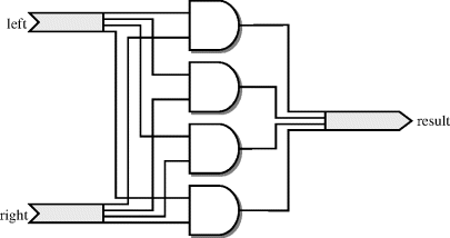
The basic and operator is defined for one-bit types and arrays. It has two arguments and as a result the same type and size. Each bit of the result is created by combining the corresponding bit from each argument, as illustrated in Figure 5.1.
Figure 5.1 Basic and operator.
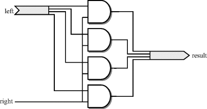
The selecting and operator is defined for an array type so that one argument is the array type, the other is the element type. The result is also the array type and has the same size as the array argument. Each bit of the result array is created by combining the corresponding input array element single-bit input. This can be thought of as the one-bit signal acting as a select line controlling the connection from input to output. This is illustrated in Figure 5.2.
Figure 5.2 Selecting and operator.
The reducing and operator is defined for an array type and only has one argument (referred to as a unary and operator). The result is the element type of the array. All elements of the array are combined by the logic operator to form the output. This is illustrated in Figure 5.3.
Figure 5.3 Reducing and operator.

The reducing operators were introduced in VHDL-2008. Earlier versions used a function called and_reduce to do this job. These and_reduce functions are not available for the built-in types of VHDL, but are overloaded for the synthesis types described in Chapter 6. A typical reducing function is:
function and_reduce(l : <array_type>) return <element_type>;
There are seven boolean operators in VHDL. The boolean operators have self-explanatory names but nevertheless, this is what they are and what they do:
| not | inversion – true when the argument is false |
| and | and function – true when both arguments are true |
| nand | not-and function – inverse of result from and |
| or | or function – true if either argument is true |
| nor | not-or function – inverse of result from or |
| xor | exclusive-or function – true if one argument is true |
| xnor | exclusive-nor function - inverse of result from xor |
The not operator is a unary operator, that is it only has one argument. The remainder are binary operators in that they have two arguments. In VHDL-2008, all the binary boolean operators have a unary form that is the reduction operator.
The boolean operators allow boolean equations to be described. For example:
sum <= a xor b xor c;
The example is a boolean equation that forms the exclusive-or of three inputs a, b and c.
5.3.1 Synthesis Interpretation
The interpretation of boolean operators for synthesis is straightforward. Synthesisers work on a circuit representation made up of boolean equations. This internal circuit representation is usually, but not necessarily, in sum-of-products form. For synthesis, all boolean equations are transformed directly into this internal representation.
The following equivalences are used to convert each of the logical operators into sum-of-products form:
not a = not a
a and b = a and b
a nand b = not a or not b
a or b = a or ba nor b = not a and not b
a xor b = (not a and b) or (a and not b)
a xnor b = (a and b) or (not a and not b)
However, logic minimisation during synthesis will restructure the circuit anyway, so these equivalences will generally not be seen in the final synthesised circuit.
There are six comparison operators, all of the same precedence. The six comparisons are:
| = | equality |
| /= | inequality |
| >= | greater-than-or-equal |
| > | greater-than |
| <= | less-than-or-equal |
| < | less-than |
All types have equality and inequality operators; most types have all six operators.
The most obvious use of comparison operators is for testing numeric types. However, they can also be applied to any other types, including arrays.
The form of a comparison is:
if a < b then
The result of the comparison is type boolean, which was dealt with in Section 4.5 Boolean is a logical type and so relationships can be combined using the boolean operators.
For example:
if a = 0 and b = 1 then
The example shows how two comparisons have been combined with an and function. The result of this test will only be true if both conditions are true, that is if a is 0 and b is 1.
The relational operators have a higher precedence than logical operators. This means that the comparisons are calculated first and then combined with the logical operators. No parentheses are needed to enforce this ordering, but parentheses would be needed to override it.
The example above is equivalent to:
if (a = 0) and (b = 1) then
5.4.1 Synthesis Interpretation
The circuits produced from the comparison operators are different for integer types (including enumeration types that are synthesised as small unsigned integers) and for array types. It is important to realise that array comparison is different from numeric comparison. For example, when using a bit_vector to represent an integer, the comparison operators will not give a numeric ordering. It is considered bad practice to use bit_vector to represent integer values anyway, since the array types described in Chapter 6 should be used for this purpose.
5.4.2 Integer and Enumeration Types
There are two basic circuits used to perform comparisons. One circuit performs the equality tests ("=", "/="), the other performs the ordering tests ("<", "<=", ">", ">=").
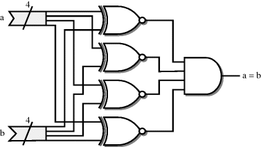
Equality is performed as a bit-by-bit comparison. Each bit is compared using an xnor function and the results of the individual bit comparisons are then anded together. For example, Figure 5.4 shows a 4-bit comparison.
Figure 5.4 Four-bit equality.
This circuit is the same regardless of the type being compared. One-bit types such as bit for example are the simplest form of this circuit, using just a single xnor function.
Inequality uses exactly the same circuit with the output inverted.
The circuit used for the four ordering operators is based on a subtracter. The sign bit of the result of a subtraction can be used to test whether the result is negative. This fact is used to perform the less-than operation. If the first operand is subtracted from the second and the result is negative, then the second operand must be less than the first.
The circuit used for comparison is shown in Figure 5.5, which shows a 4-bit less-than operation. Of course, the synthesiser will optimise the circuit to remove the logic for generating the unused subtracter outputs.
Figure 5.5 Four-bit less-than circuit.

The exact circuit used for the subtracter depends on the type being compared. For integer types it will be an integer subtracter, for fixed-point types a fixed-point subtracter and so on.
The remaining three comparisons are all performed by the less-than operation, with various permutations of exchanging the inputs and inverting the output.
The equivalences are:
a > b = b < a
a >=b = not (a < b)
a <=b = not (b < a)
Synthesis can be simplified further when comparing with zero. Bear in mind that the sign bit alone is a test for a number being less than zero (if it is 2's-complement that is). It follows that the inverted sign bit is a test for greater-than-or-equal to zero. Both of these tests require no comparator at all.
Contrast this with the test for a signal being greater than zero. Using the equivalences above, the test for signal a being greater than zero is:
0 < a
The sign bit is no help here, so this is implemented as a subtracter. This is clearly a much larger circuit than that used for the test for a being less than zero. The same subtraction circuit with inverted output is used for testing less-than-or-equal to zero.
In summary, the test for less-than zero (< 0) and for greater-than-or-equal to zero (>= 0) are very efficient, whereas the tests for greater-than zero (> 0) and for less-than-or-equal to zero (<= 0) are much less efficient.
5.4.3 Array Types
The equality operator ("=") has two interpretations when comparing arrays. If the two arrays being compared are of different lengths, then they cannot be equal and the equality operator is implemented by the false value – that is, by logic 0. If the two arrays are of equal length, then the equality of the arrays is the individual equalities of the elements all anded together. The circuit is illustrated in Figure 5.6.
Figure 5.6 Array equality for arrays of equal length.

If the array element type is a one-bit type such as bit or boolean, then the equality operator for the element is just an xnor function and so the array equality becomes the same as the integer equality described earlier. In other words, array equality of an array of one-bit values will give a numeric comparison provided the two arrays are the same length.
Inequality ("/=") uses the same circuit but with the output inverted.
The real difference between integer comparison and array comparison is with the ordering operators ("<", ">", "<=" and ">=").
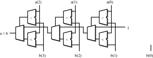
The algorithm for the less-than operator ("<") will be used as an example. The elements of the arrays are compared from left to right regardless of their ranges. Each bit is tested for equality until unequal elements are found. If a pair of elements are not equal, then the array with the smaller element at that position is regarded as less than the other array. If the end of either array is reached before any unequal elements are found, then the shorter array is regarded as less than the longer array.
The array less-than circuit is illustrated in Figure 5.7. It has been drawn with an unconventional circuit flow from right to left to reinforce the fact that the elements are compared from left to right. In other words, the leftmost elements are the highest priority and so are shown nearest to the circuit output. If the leftmost elements are unequal, then that determines the output. If they are equal, then the result from the previous bit is rippled through. This circuit is iterated for each bit in the arrays, stopping at the end of the shorter array. The input of the rightmost circuit is the result of the length ordering. In this case, the first operand (a) is shorter than the second operand (b) and so the result of the less-than comparison is true if all the elements up to the length of the shorter operand are equal. The true value is fed in at the end of the comparison chain as the value 1. The trailing element of b does not participate in the comparison.
Figure 5.7 Array less-than operator.
Note that, for the numeric types described in Chapter 6 that implement integer, fixed-point and floating-point values as arrays, these operators have been replaced with ones that give the correct comparison circuit for the type. This explanation only applies to other array types that do not have a numeric interpretation. This includes bit_vector and any user-defined array types.
Shifting operators are only built-in for arrays of type boolean or bit. This means that the only standard type that has shift operators is bit_vector.
The description here describes the built-in shift operations for bit_vector.
In fact, these operators have also been added to std_logic_vector and the numeric packages but with a slightly different interpretation – see Chapter 6 for details.
The shifting operators are:
| sll | shift-left logical |
| srl | shift-right logical |
| sla | shift-left arithmetic |
| sra | shift-right arithmetic |
| rol | rotate-left |
| ror | rotate-right |
The general form of a shift expression is:
z <= a sll 1;
The result z must be the same array type and the same length as the left-hand operand a, whilst the right operand is an integer value representing the shift distance.
The logical shifts simply shift the operand, discarding bits that are shifted off one end and filling the other end with the left-most value of the element type. This means that arrays of type bit will be filled with the '0' value.
Assuming that a is a bit_vector with the value "00001111", then the value of z after the one-bit left shift will be "00011110".
The right shift works in a symmetrical way:
z <= a srl 1;
In this case, with the same value of a, then the value of z after the one-bit right shift will be "00000111".
The arithmetic shifts are quite unusual and of very little use on most array types. They are overloaded for array types that do have a numeric representation so that they do perform arithmetic shifts. Again, see Chapter 6 for details of the numeric array types.
The left arithmetic shift extends the rightmost bit just as if it was a sign bit. This rightmost bit is shifted in at the right-hand end as the array is shifted to the left. For example, if a is a bit_vector and has the value "00001111", then a left shift of one bit will give the value "00011111". In right shifts it is the leftmost bit that is duplicated and shifted in at the left-hand end.
The rotate operators take elements off one end of the array and shift them in at the other end. In left shifts, elements are shifted off the left end and in at the right, whilst in right shifts, elements are shifted off the right end and in at the left.
For example, "11110000" rotated left by one bit is "11100001" and shifted right by one bit is "01111000". This has no numeric equivalent – it is purely a logical operation.
5.5.1 Synthesis Interpretation
The shift operators have two different synthesis interpretations depending on whether the shift distance is a constant value or a signal or variable.
5.5.1.1 Constant Shift Distance
For a constant shift distance, the shift operators are implemented as a fixed rearrangement of the bits of the bus. There is no logic circuitry generated.
The shift-left logical (sll) operator is implemented as a left offset of the bits of the bus, with the rightmost bits connected to zero to represent the shifting in of zeros. The circuit is illustrated by Figure 5.8 which shows a shift-left of 4 bits.
Figure 5.8 Shift-left logical (sll) by 4 bits.
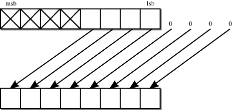
The shift-right logical (srl) operator is symmetrical to this, as would be expected for a logical operation.
The shift-left arithmetic (sla) is also implemented as a left offset of the bits of the bus. The rightmost bit is replicated by simply fanning out this bit to all the bits left open by the offset. The resulting circuit for a shift of 4 bits is shown in Figure 5.9.
Figure 5.9 Shift-left arithmetic (sla) by 4 bits.
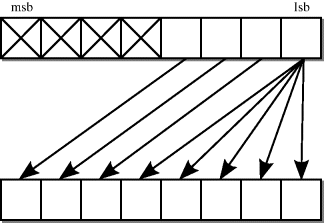
The shift-right arithmetic (sra) operator is symmetrical to this.
The rotate operators cause a crossover in the bits of the bus, because the bits shifted off one end of the bus are shifted back in at the other end. The resulting circuit for a rotate-left (rol) of 1 bit is shown in Figure 5.10.
Figure 5.10 Rotate-left (rol) by 1 bit.
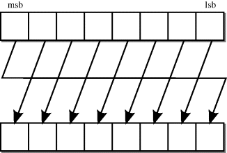
Once again, the rotate-right (ror) operator is symmetrical to this.
5.5.1.2 Variable Shift Distance
If the shift distance is a variable quantity, such as a signal, variable or complex expression, then the shift is implemented as a barrel shifter logic block. This is a predefined circuit provided by the synthesis vendor for performing variable shifts.
The arithmetic operators are:
| + | addition |
| − | subtraction |
| + | plus sign |
| − | minus sign |
| ∗ | multiplication |
| / | division |
| mod | modulo arithmetic |
| rem | remainder after division |
| ∗∗ | exponentiation |
| abs | absolute value |
5.6.1 Synthesis Interpretation
The circuits that logic synthesis will use for the arithmetic operators will vary according to the type, so for example integer types will have integer operators, fixed-point types will have fixed-point operators and so on. The exact circuits can also vary from synthesiser to synthesiser and from technology to technology, although the calculated results will always be the same between technologies. In general, the circuit used for an arithmetic operator will be the minimum area circuit that implements that function entirely in combinational logic. The operator must be implemented combinationally because registers must be specified explicitly for logic synthesis.
The circuits given in the following sections are examples of the way in which a synthesiser might implement the standard arithmetic operators for the built-in types. This subject will be revisited in Chapter 6 where the numeric synthesis types are described. They are all minimum or near-minimum circuits. However, it should be realised that different synthesisers will give slightly different circuits, particularly for the multiplication and division operators. Furthermore, synthesisers allow a choice of different area/speed trade-offs to be made by providing a range of implementations for the operators. These are selected by the synthesiser to meet timing requirements. Typically, a synthesiser will first try the minimum area circuit given here, then if the circuit is too slow, faster but bigger circuits are substituted until the timing requirements are met. This is a very powerful technique and it means that designers will probably never have to design arithmetic circuits at the gate level or even the boolean equation level, even for high-speed applications.
Part of the learning process of using synthesis is to allow the synthesiser to make this choice of implementation rather than trying to control every detail of the design yourself. So you don't need to know which implementation is used as long as the timing requirements are met.
5.6.2 Plus Sign
The plus sign has no effect whatsoever on the value of a signal and so has no circuit to implement it; it can be thought of as simply a feedthrough.
5.6.3 Minus Sign
The minus sign is implemented as a 2's-complement negation. 2's-complement negation is performed by subtracting the input from zero.
5.6.4 Abs Operator
The abs operator is simply a combination of the two sign operators with a multiplexer controlled by the sign bit, to choose between whichever of the operand and its negation is non-negative. The circuit for the abs operator is shown in Figure 5.11.
Figure 5.11 Abs operator.
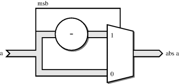
5.6.5 Add Operator
The add operator is implemented in its minimum form as a ripple-carry adder. However, there are many other faster implementations such as carry lookahead adders. Each technology will provide a range of adder circuits for the synthesiser to use with different speed/area tradeoffs. It is the synthesiser's job to select the appropriate implementation for each add operator.
If the operands of the addition are of different lengths, then the shorter operand will be extended to the same length as the longer one. Unsigned numbers are zero-extended, whereas signed numbers are sign-extended. This means that, in practice, signed and unsigned addition can require slightly different circuits.
It is questionable whether it is worth optimising the number of adders in a circuit since the hardware area and delay cost of multiplexing several different inputs onto a single adder may outweigh the saving in adder circuitry.
5.6.6 Subtract Operator
The subtracter is a very similar circuit to the adder. The technology library will provide a similar range of subtracters as adders. Also, the synthesiser can map the subtraction onto an adder/subtracter circuit.
For example, consider the following code fragment:
if do_add = '1' then
z <= a + b;
else
z <= a - b;
end if;
Since the inputs of the addition and the subtraction are the same, and the conditional makes them mutually exclusive (i.e. only one can be required at any one time), the synthesiser may be able to map this onto a single adder/subtracter circuit rather than separate circuits.
5.6.7 Multiplication Operator
Multiplication has a different implementation depending on whether the operands are signed or unsigned. However, for both cases, the minimum-area combinational implementation of multiplication is a essentially a matrix of full-adders. The point is that the area of a multiplier is proportional to the square of the word length, whilst the delay is proportional to the word length.
Multipliers can take arguments of different length and there is no extending of the shorter argument. Instead, this is used as an optimisation. For example, given a 32-bit input and a 16-bit input, a 32 × 16 multiplier can be generated, rather than normalising the inputs and generating a 32 × 32 bit multiplier that has twice the area.
A multiplier is a large circuit and has many possible implementations, far more than an adder. Most technology libraries will provide a wide range of designs with different speed/area tradeoffs. It is usually not necessary to try to re-implement multiplication as a multi-cycle operation since combinational multipliers are sufficiently efficient for most designs.
Nevertheless, one of the key optimisations that you can do as a designer is to reduce the number of multipliers by multiplexing arguments onto a single multiplier block.
5.6.8 Division Operator
For many years after the advent of synthesis tools, division was considered an unsynthesisable operator. This is because, in RTL synthesis, all operators must be implemented as combinational logic. The exception was when the right-hand operand (the divisor) was a constant power of two, which allowed the division to be replaced by a shift operation.
However, both ASIC and FPGA technologies have advanced and division is now considered a synthesisable operator. It is typically implemented as a series of subtract and shift operations, bearing in mind that they are all combinational.
This is a larger and slower circuit than multiplication and it may make more sense to use a circuit that implements division over several clock cycles. Such circuits may be provided by the technology vendor or can be licensed from core design services.
Nevertheless, division can be synthesised and will result in a combinational division circuit. It is still the case that if the right-hand operand is a constant power of two, the division will be replaced by a shift operation.
5.6.9 Modulo Operator
The mod operator performs modulo arithmetic. It maps a number onto a restricted range specified by its second operand. It is closely related to division, and requires a similar circuit.
Like division, if the right-hand argument is a constant power of two, the modulo can be mapped onto a simpler operation, in this case a masking operation.
To give an example, the following is a modulo-4 addition:
(a + b) mod 4
The result of this expression will be mapped onto the range 0–3.
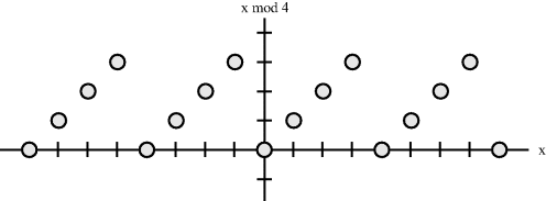
Figure 5.12 shows the mapping from an integer value (shown on the x-axis) onto its modulo 4 (shown on the y-axis).
Figure 5.12 Mapping of modulo-4 operator.
The implementation is very simple. The modulus of a number is found by simply discarding the m.s.b.s and keeping the number of l.s.b.s required to represent the range of the modulo arithmetic. This is a masking operation in which the m.s.b.s are removed, leaving just the l.s.b.s intact. For example, modulo 4 requires 2 bits to be kept and the rest to be masked. Figure 5.13 shows the modulo 4 conversion of a 4-bit bus.
Figure 5.13 Unsigned and signed modulo-4.
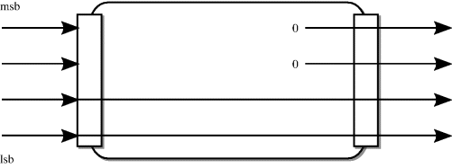
Examination of the 2's-complement representation of negative numbers shows that in fact, the masking operation used for unsigned modulo arithmetic also works correctly for signed modulo arithmetic.
When the right-hand argument is variable, the operator will be mapped onto a combinational divider circuit. Again there will be a set of implementations specific to the technology being synthesised to.
5.6.10 Remainder Operator
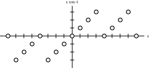
The rem operator calculates the remainder after a division. The difference between modulus and remainder only applies to negative numbers: the remainder preserves the sign of the number being divided, whereas the modulus preserved the sign of the divisor, in this case positive.
For unsigned numbers, there is no sign and the remainder is exactly the same as modulus, giving exactly the same circuit.
For signed numbers, the result can be negative. Figure 5.14 shows the mapping from an integer value (shown on the x-axis) onto its remainder for division by 4 (shown on the y-axis).
Figure 5.14 Mapping of remainder operator.
The remainder function requires the same circuit is the division operator, not surprisingly since it is the remainder after division. So the same arguments regarding implementation of the remainder apply as to the division operator.
5.6.11 Exponentiation Operator
The exponentiation operator is not generally synthesisable. However, there are two constrained forms where it can be used. The first is where the left hand argument is 2, so it is possible to calculate 2n. The second is where the right-hand argument is 2, so it is possible to calculate the square, x2.
The calculation of 2n is transformed into a shift operation, since this is equivalent to shifting the value 1 by n bits.
The calculation of the square, x2, is done by mapping the exponent onto the multiplication operator:
x**2 = x * x
The appropriate multiplier is then used to form the square. Note that, even though the square can never be negative, the result will be a signed number if the argument is a signed number, since that is the behaviour of the multiplication operator.
The concatenation operators allow an array to be built up out of smaller arrays and elements. There are in fact four concatenation operators defined for any one-dimensional array type. All return the array type; the difference between the operators is in the argument types that they take. There are four operators because there are four possible permutations of the array type and its element type. All these permutations are provided.
For example, type bit_vector has an element of type bit. Therefore, there are operators to concatenate two bit_vector operands, a bit with a bit_vector, a bit_vector with a bit and finally an operator to concatenate two bit elements, all producing a bit_vector.
In hardware terms, concatenation of arrays is equivalent to the merging of buses to form a larger bus. There is no circuitry involved, just wires. For example, consider the following fragment of VHDL:
signal a, b : bit_vector (3 downto 0);
signal z : bit_vector (7 downto 0);
...
z <= a & b;
This merges two 4-bit buses into an 8-bit bus. The ordering of the bits in the result is a left to right ordering, with the leftmost bit of a on the left of the result and the rightmost bit of b on the right of the result.
