Perhaps no other piece of equipment exemplifies video production like the video camera does. It is, in many ways, the symbol of video production, and most video work begins with raw images, captured and recorded by the video camera.
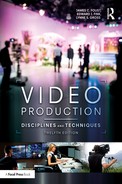
A wide variety of cameras are available for video production, ranging in price from a couple hundred dollars to more than $100,000. Increasingly, mass-market cameras at consumer price points and cameras that are integrated in smartphones or other devices are finding their way into professional video production as well. In addition, most digital SLR (DSLR) cameras of the type traditionally used by professional still photographers now have the capability to shoot high-quality video. Figure 5.1 shows examples of the wide range of camera types available for video production.
Some cameras—usually those near the high end of the price range—are intended for use exclusively in the studio, while others are designed for field use. An increasing number of cameras are designed to be adaptable to either type of production environment. All cameras, however, perform the same basic function: transducing, or converting physical energy in the form of light waves into electrical signals. What happens to these signals after they leave the camera is discussed in later chapters, as this process varies according to the production situation. In studio productions, the output of one or more cameras will be routed through a switcher (see Chapter 9) and then broadcast live or recorded (see Chapter 10). In field work, the signal is recorded (see Chapter 10) and then edited (see Chapter 11).
This chapter introduces the basic function and operation of the video camera and its integral lens and mounting systems. It also discusses aesthetic considerations, including picture composition principles and basic shot types. Like any piece of production equipment, the video camera is a tool, and using that tool to its greatest functional and creative potential requires an understanding of both disciplines and techniques. These include not only how to operate the tool but the underlying technical principles that make the tool work.
Television Formats
As discussed in Chapter 1, ATSC formats have for the most part replaced the NTSC format. For that reason, this chapter (and this book in general) emphasizes ATSC technology. However, because it is possible that you may still run into NTSC cameras and other equipment—especially in a school setting—we will mention the differences where they are relevant. Overall, both types of cameras operate and are used in the same way.
The Video Scanning Process
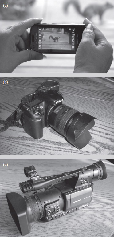
Cameras transduce light into electrical signals through a process called scanning. The video picture that you see on any television monitor—no matter what the format—is composed of a series of small, illuminating phosphors called pixels (short for “picture elements”). The pixels are arranged in a grid pattern made up of horizontal rows and vertical columns, as shown in Figure 5.2. As different pixels in the grid illuminate, different colors and shapes are created on the screen. The more pixels in each frame, the higher the resolution, or fineness of detail, that can be reproduced on the screen. In television, resolution is often indicated in lines, referring to the number of horizontal rows of pixels in the picture—the higher the number of lines, the greater the resolution. We also refer to the size of the screen grid for a given format, and when we do so we refer to the number of columns first. Thus, when referring to a format with 720 horizontal lines of resolution, we say the screen size is 1,280 by 720: 1,280 pixels wide (columns) and 720 pixels high (rows).
During the transducing process, the video camera produces a rapidly changing series of still images, each made up of thousands of pixels “drawn” electronically. These still images are called frames, and the actual number of pixels that make up each frame depends on the format, as you will see. The movement of images on the screen is an illusion caused by a phenomenon known as persistence of vision, in which the human eye perceives smooth movement of an image when its position is changed rapidly on the television screen.
The number of frames contained in each second of video is called the frame rate, measured in frames per second (fps). The higher the frame rate, the smoother the motion appears on the screen. In the United States, the most common frame rates for professional-quality video are 24, 30, and 60 fps. Due to bandwidth considerations, which are discussed in Chapter 10, lower frame rates may be used in applications designed for the Internet or viewing on portable devices such as smartphones or computer tablets.
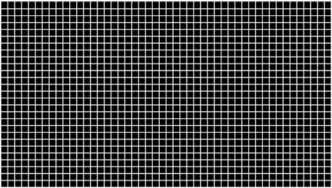
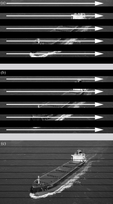
There are two methods of displaying the individual frames: interlace scanning and progressive scanning. In interlace scanning, as shown in Figure 5.3, each frame is created by first drawing the odd-numbered lines and then the even-numbered lines. Each of these picture halves is called a field; two fields, then, make up a complete frame. Thus, an interlace scanning system made up of 30 frames per second actually contains 60 fields per second. Progressive scanning, on the other hand, creates an entire frame with each pass, as shown in Figure 5.4. Thus, there are no fields in progressive scanning, only frames.
Progressive scanning creates a clearer picture than interlace scanning, all else being equal. Interlace systems can suffer from a subtle flicker effect caused by the fact that every other horizontal line is being displayed at a slightly different time. Progressive scanning also decreases horizontal distortion in fast-moving objects. The advantage of interlace, however, is that it is less resource intensive, requiring less bandwidth than comparable progressive systems.
Video Formats
As we know, ATSC encompasses a number of different formats. Some of these use progressive scanning, while others use interlace. Frame rates and screen resolution also vary among the formats.
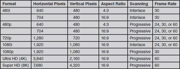
Figure 5.5 shows some of the formats available in ATSC. The formats are usually referred to using the number of lines and then either an “i” for interlace scanning or a “p” for progressive scanning. For example, 480p refers to the format with 480 lines and progressive scanning. From among the many different formats initially available, the industry has settled on five standards: 480p, 720p, 1080i, 1080p, and 2160p (also referred to as “4K” or “Ultra HD”). In addition, some formats are referred to as 24p. In this case, the number indicates not lines of resolution but frame rate, which is in this case the same frame rate traditionally used in film production.
You will notice that most ATSC formats use the wide 16:9 aspect ratio. This is closer to the aspect ratio used in film production and generally considered to be more pleasing to the human field of vision. The 4:3 aspect ratio formats are essentially a legacy of the NTSC format, which used that screen shape exclusively. These aspect ratios are shown in Figure 5.6.
Another legacy of NTSC worth pointing out is the difference between standard-definition (SD) and high-definition (HD). The NTSC format used a frame size of 480 lines and 640 columns; thus, formats that use that same resolution (either NTSC or ATSC) are referred to as standard-definition.1 Formats that use larger frame sizes are referred to as high-definition.
Principles of Video Color
As discussed in the opening of this chapter, the video camera essentially converts the light energy reflected off objects into an electrical signal. To understand how this is accomplished, it is important to comprehend some principles of how colors are processed by a video camera and how humans perceive color.
Light enters a camera through the lens, which focuses it onto one or more image sensors, computer chips that transduce the light energy into a digital signal. Some cameras have a single image sensor, while others have three. On three-chip cameras, each image sensor chip is designed to process the color information for one of the primary colors—red, green, and blue. A device called a beam splitter, which is essentially a light prism, separates the incoming light into the three primary colors, directing each set of color information to the appropriate image sensor. On single-chip cameras, one chip processes all color information. Three-chip cameras normally provide a much higher-quality picture than single-chip cameras, but they are more expensive as well.
Image sensor chips can be one of two main types: charge-coupled device (CCD) or complementary metal oxide semiconductor (CMOS). Although CCD image sensors were once dominant, CMOS sensors have nearly completely replaced them in the past few years. CMOS offers lower power consumption, lower cost, higher image quality, and “camera on a chip” technologies that can replace the CCDs and circuitry of a traditional camera with a single microchip. One of the driving forces behind the adoption of CMOS sensors, in fact, has been their prevalence in smartphone cameras, which has spurred further development for higher-end applications as well.
Video cameras and video display devices (such as television monitors), like the human eye, are sensitive to three attributes of color: hue, saturation, and luminance.
Hue
Hue refers to the color tint itself. The three primary colors (red, green, and blue) can be combined to produce the three secondary colors: cyan (a turquoise formed from blue and green), magenta (a blending of red and blue), and yellow (the combination of red and green). These primary and secondary colors are the basic pure hues seen when a prism breaks up white light into its individual color components or when we marvel at a rainbow, which is essentially millions of water droplets acting as tiny prisms to create vivid primary and secondary colors.
When light waves of all three primary colors are added together in a proportion that relates to the color sensitivity of the human eye (59 percent green, 30 percent red, and 11 percent blue), the resulting effect is white. Sometimes thought of as the absence of color, white is actually the presence of all colors. If you have trouble accepting this on faith, prove it by looking carefully at the individual grains of sand that make up a white sandy beach. The variety of colors that we are used to seeing in our daily lives results from the reflected combination of these primary colors.
Because the proportions among combined hues can vary, an enormous range of colors is possible. For example, when red and green are added together, a range of pure hues from red to orange to yellow to green can be created. As the third primary color, blue, is added, a wide variety of browns, tans, mahoganies, beiges, ochers, maroons, sepias, and so forth are achieved. You may have experimented with this using a computer design program that has the ability to mix ultrafine gradations of color and, as a result, can create literally millions of different hues.
Saturation
Saturation describes the intensity or vividness of a color. When dealing strictly with a red hue, for example, the intensity can range from a highly saturated vivid red to the less saturated pastel red. The pastel red is achieved by diluting the color with white. Another effect is achieved by diluting the vivid red with gray, producing more of a brown tone.
As other hues are blended together, additional colors result. Red and green hues combined in varying proportions with different amounts of white produce yellows. If increasing amounts of gray are used to dilute the saturation of the red and green factors in this yellow, a series of golden brown tones will result. Just as the saturation effect can be controlled on a scale leading to white, gray exists on a scale of increasing darkness leading to black. Together, the hue and saturation portions of a video picture are termed chrominance.
Luminance
The final color attribute is the luminance, or brightness, of the color. Colors with low brightness are darker than their high-brightness counterparts. For example, we could start with a very bright red—the color on a stop light, for example—and then decrease the brightness, working through a blood red color, then to a series of brownish reds and eventually to black. The luminance of a color is not to be confused with video gain, which increases (or decreases) the brightness of an entire picture through amplification of the video signal, as will be discussed in the next section. Luminance refers to the brightness of an individual color displayed on the screen.
Lens Characteristics
Possibly the most crucial element in the whole process of producing video pictures is the lens. The quality of the lens, to a large extent, can determine the quality of the picture produced by a particular camera and, consequently, the quality of the picture seen on the home TV screen or studio monitor. A high-quality lens on a lower-end camera can improve its output significantly, and by the same token a low-quality lens on a high-end camera can substantially drag down the quality of the picture. A wide variety of lens types are available for video work; this section looks at some characteristics common to all lenses.
Focal Length
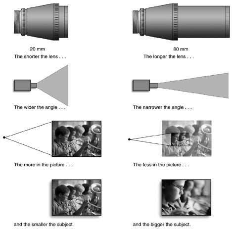
From an operational standpoint, the focal length of a lens determines how wide or narrow the viewing range or field of view is.2 Differing focal lengths are used primarily so that differing amounts of a scene can be included in the picture when shot from the same position. The longer a lens is, the narrower its viewing angle will be, and the less you will be able to fit into the picture. Therefore, a long lens magnifies individuals. Conversely, a short-focal-length lens gives you a wider viewing angle, allowing you to fit more into the picture. But individual subjects will appear smaller. This concept is illustrated in Figure 5.7.
A long lens, or telephoto lens, therefore, can be used to obtain close views of objects and can get a relatively close-up view of an object from a great distance. A long lens will compress distance. Two objects that are far apart from each other and at a great distance from the camera will appear closer to the camera with a long lens and, consequently, will seemingly be brought closer to each other. A common example is the shot of the baseball pitcher and batter as seen with a telephoto lens from center field, perhaps 400 feet away. Although the pitcher and batter are about 60 feet apart, the long lens makes it look as if the two players are much closer to each other. On the home screen, they may look as if they are only 10 or 15 feet apart. Conversely, a short lens, or wide-angle lens, will increase the illusion of distance and make the pitcher and the batter look farther apart than they are.
Although fixed-focal-length lenses, which can provide only one range of view, were common on cameras in the early days of television, now a zoom lens is found on nearly every video camera. Unlike a fixed-focal-length lens, the field of view of a zoom lens is continuously variable along a range of focal lengths. Thus, a zoom lens in effect mimics the field of view of a series of fixed-length lenses: a zoomed-in lens may be equivalent to a long-focal-length fixed lens, while a zoomed-out lens may be equivalent to a short-focal-length fixed lens.
It is important to point out the difference between optical zoom and digital zoom technology. Optical zoom technology uses a series of glass pieces inside the lens that move to provide different magnifications of the field of view. When you zoom in or out, the spatial relationship between the glass pieces changes and provides a narrower or wider view. Digital zoom, on the other hand, electronically magnifies the field of view after it comes through the lens. It is akin to using the zoom feature in a program like Adobe Photoshop to magnify an image. Digital zoom is found mostly on low-cost cameras; some cameras, in fact, may use a combination of optical and digital zoom. Although digital zoom technology is improving, optical zoom provides a much more realistic zoom effect that is not subject to the pixelation that can come from digital zoom (see Figure 5.8). For that reason, optical zoom—although it necessitates heavier and more expensive cameras—is vastly preferable to digital zoom.
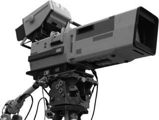
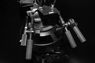
You will also notice a difference in appearance bet- ween lenses designed for studio- or stationary-camera use, such as that shown in Figure 5.9, with those that are designed for portable cameras. A studio lens usually has an enclosure that hides its moving parts; adjustments are made by pressing buttons or turning knobs that connect to the lens structure within the enclosure. For example, Figure 5.10 shows the zoom and focus controls of a studio camera located on the pan handles of the camera mount. Lenses on portable cameras, on the other hand, are exposed, and most adjustments are made by touching and moving components on the lens itself. Also, on lower-cost portable cameras, many of the lens settings described in this section are manipulated electronically, often through menu screens or buttons, rather than by physically moving parts.
Focus
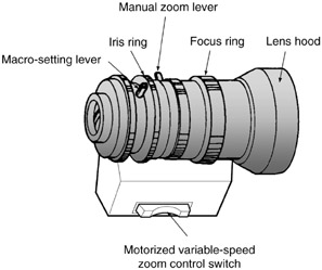
A video image is in proper focus when the subject is clear and distinct, not fuzzy or blurred. On zoom lenses, the focus control is the slip ring located farthest toward the front of the lens. (See Figure 5.11.) When a camera is set up for studio use, this ring is usually adjusted by the use of a remote-control cable. The determining factor in setting proper focus is an object’s distance from the camera lens. For example, if you focus on an object that is 4 feet from the camera, and then the object moves 20 feet away from the camera, you will probably have to refocus.

To set the focus on a zoom lens, zoom in all the way to the tightest shot possible and then adjust the focus. This is called front focus. Following this procedure ensures that the object will remain in focus throughout the range of the zoom lens (assuming, of course, that the distance between the object and the camera does not change).
The camera operator—whether in a studio or field situation—must diligently ensure that proper focus is maintained. As cameras and objects move, the distance relationship between the camera and its various subjects changes constantly. Each change necessitates checking to be sure that the lens is properly focused. Although an increasing number of cameras have autofocus, using this feature in a production environment can be problematic. For example, the autofocus will not always focus on the correct screen element, and variations in focus as the camera adjusts for proper focus can be jarring to the viewer.
F-Stop Aperture
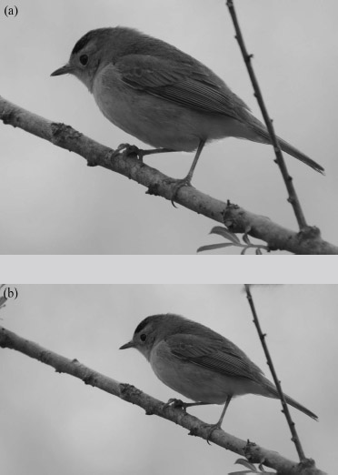
All camera lenses have an iris that controls the amount of light coming into the camera. When the iris is adjusted, it opens or closes the aperture, which is made up of a series of metal “blades” that adjust the size of the lens’s light opening. The aperture does not, however, affect the size of the picture the lens will pick up. Most cameras have an automatic iris feature in which the camera adjusts the aperture depending on the amount of light present. However, these systems are normally based on the overall amount of light in the frame and thus may not produce the proper exposure for a given effect. For example, a patch of bright sky in the shot may “confuse” the camera’s automatic iris and cause it to close the aperture, thus making the rest of the shot look too dark (See Figure 5.12.) In these situations, and for other creative reasons, the camera operator will want to override the automatic iris control and instead adjust the iris manually.

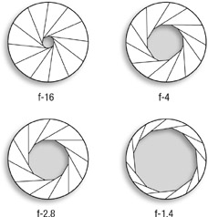
The various sizes of aperture openings are identified by f-stop numbers. The lower the f-stop number, the larger the lens opening (allowing more light), and the higher the f-stop number, the smaller the lens opening (allowing less light). (See Figure 5.13.) For instance, f-22 is typically the smallest aperture found on most television lenses, for use in situations with intense light. The widest opening may be f-2.8, depending upon the lens, for use in low-light situations. In between, the numbers range from 4, 5.6, 8, 11, to 16. The change from one stop to the next represents either the doubling or the cutting in half of the amount of light being allowed into the camera. It is a precise measurement, hence the need for some decimal figures.
If you are working under very poor lighting conditions with no option for increasing the amount of light, for example, it might be advisable to open up to f-4. On the other hand, if working under extremely bright conditions (perhaps outdoors on a sunny day), you might want to stop down to f-11 or f-16. The term stop down, which actually means closing up the iris to a higher number, may take a little getting used to, but it’s the accepted phrase.
One word of warning about f-stop adjustments: Generally speaking, the camera operator should not routinely change the f-stop to compensate for bad lighting. Bad lighting or uneven lighting should be handled by correcting the lighting, not by adjusting the camera.
In addition to the lens’s f-stop controls, many cameras have an automatic gain control (AGC) that adjusts video levels to compensate for differing light levels. Other cameras have a video output control that allows the operator to boost the signal in low light levels. The level of boost is measured in decibels (dB), and each 6 dB increase in gain doubles the signal amplification. The “0 dB” position is established as the standard level of video output for the camera under normal lighting conditions. Like f-stop adjustments, this control should never be thought of as a way to make a poorly lit picture better. All it can do is make the picture look a little brighter. Increasing the automatic gain control above 0 dB also usually makes the picture appear more grainy; the higher you set the gain, the grainier the picture.
Depth of Field
The distance between the nearest point at which objects are in focus and the farthest point at which objects are in focus in a given shot is called depth of field. Once the focus is set for a specific object, other objects closer to the camera will be out of focus, as will objects located farther away. Making sure that you can predict the location and range of the middle ground where objects are in focus is important in the production planning process.
Three different factors coincide to determine the depth of field: the f-stop (the smaller the lens opening, the greater the depth of field); the distance from the subject to the camera (the greater the camera-to- subject distance, the greater the depth of field); and the focal length of the lens (the shorter the lens, the greater the depth of field). Figure 5.14 illustrates these three variables.
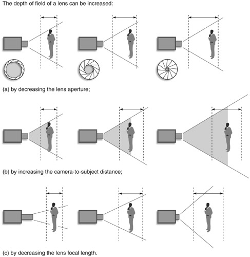
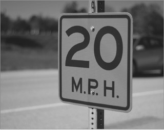
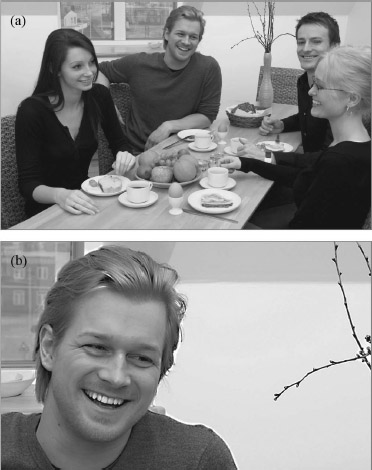
Depth of field is often manipulated for artistic effect. In some situations, such as sporting events, you might want to have a very large depth of field so that rapidly moving action will stay in focus. In an interview situation, you might want to have narrower depth of field so that the element in focus (the person being interviewed) is separated from the background. Figure 5.15 shows another artistic effect created by a narrow depth of field. The best way to increase the depth of field is simply to add light and stop down the lens. This allows the shot to remain the same, which would not be the case if you attempted to change the focal length with a zoom movement or to change the camera-to-subject distance. Similarly, depth of field can be decreased by moving the camera farther away from the subject and zooming in, or by opening up the lens. The latter technique means you will have to either reduce the amount of light on the subject or reduce the amount of light entering the camera by using a neutral density (ND) filter, as discussed in the section on camera controls.
Another artistic effect that relates to depth of field is called the rack focus. In this type of shot, the camera operator brings one object in the frame into focus while the other objects remain blurred. Then the operator smoothly adjusts the focus so that a different object in the frame comes into focus and the initial object becomes blurry. For example, the camera may start on a tight close-up shot of a half-empty glass close to the camera with the background out of focus; the camera operator then changes the focus to a person lying on the sofa beyond the half-empty glass, while the glass goes blurry. Such shots tend to be most dramatic when the depth of field is relatively narrow.
3D and Virtual Reality
The desire to overcome the two-dimensional (2D) limitations of the movie screen or video monitor has long been a part of video production. Both three- dimensional (3D) production and virtual reality seek to convey a more immersive experience for the viewer, using technology to provide a more realistic experience: 3D conveys a sense of depth to scenes, making it look, for example, as if a bird is flying directly at the viewer. Virtual reality can replicate a real 360-degree environment, allowing a viewer wearing special goggles to experience and even “move” through a virtual three-dimensional space.
Although, historically, 3D production took place at the fringes of the art (in campy “B movie” horror films, for example), advances in technology and production have made it possible for 3D production to be much more realistic. While some movies are shot in native 3D using sophisticated dual-camera systems, most recent 3D movies were shot in 2D and then converted to 3D after shooting. This can be a more cost-effective option for movie studios and can also allow for the conversion of existing 2D movies to 3D. However, even though 3D movies remain popular in action, animation, and fantasy genres, the excitement brought by 3D movies such as Avatar in 2009 has not translated into long-term adoption of the technology by either filmmakers or the viewing public. Most notably, sales of 3D-capable home televisions and disc players have dropped off after strong initial sales. 3D is likely to remain viable as a niche production area, but mainstream adoption of the technology is currently stalled.
Virtual reality, on the other hand, is rapidly increasing in popularity, driven by its adoption by major technology companies such as Google and Oculus. Virtual reality scenes can be created using animation (such as in a video game) or with actual video. When based on video, most virtual reality systems actually take multiple shots of the same scene and then use software to “stitch” the videos together to create 3D spaces. The concept is not unlike the feature in many mobile phones or point-and-shoot cameras that allows a user to take multiple pictures of a landscape and then assemble the pictures together into a panorama view. For example, GoPro’s Odyssey system uses 16 individual cameras mounted on a 360-degree mounting rig. The Odyssey system is optimized for use with Google’s Jump software assembler. Virtual reality headsets also come in a variety of types. Many feature both goggles and touch controllers that allow the user to “pick up” virtual objects and make gestures with their hands. Lower-cost devices sometimes use a smartphone attached to the front of the headset, allowing the viewer to experience virtual reality videos uploaded to YouTube.
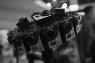
Figure 5.16 A multiple-camera system designed to shoot virtual reality. (Courtesy of Shutterstock.)
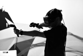
Figure 5.17 A virtual reality headset with hand controllers. (Courtesy of Shutterstock.)
Production Use of the Zoom
The zoom lens allows camera operators and directors to achieve rapid and continuous adjustment of the focal length of the lens and, consequently, to control precisely the size and framing of shots. In addition to giving the director and camera operator a wide range of lens lengths that are immediately available, the zoom lens also facilitates very smooth on-the-air movement.
The variable-focal-length zoom lens is essentially an arrangement of gears connected to optical elements that move back and forth in relation to each other. This achieves varying focal lengths by changing the theoretical center point of the lens. Zoom lenses vary greatly with price and manufacturer, but lenses designed for professional and industrial levels all share some of the same basic characteristics.
Lens Ratio
For many production situations, a 10-to-1 magnification ratio is sufficient. On a typical lens, this results in focal lengths ranging from 10.5mm at the wide-angle position to 105mm at the zoomed-in position. Figure 5.18 indicates the range of shots available with a 10-to-1 zoom ratio lens. Many studio cameras are equipped with 20-to-1 lenses, while field cameras often have lenses in the range of 15-to-1. For sporting events and other outdoor productions, cameras with zoom ratios of 30-to-1 and greater are common. The use of an extender increases the focal length of a lens, allowing it to zoom in even closer to distant objects. A 2X extender, for example, doubles the focal length of the zoom lens at both the wide-angle and the zoomed-in positions. Some extenders are placed between the zoom lens and the camera, while others are built into the zoom lens itself. On these latter types, the camera operator can select either normal or extended lens lengths.
Movement Control
Virtually all zoom lenses have a motor-driven zoom mechanism. Less-expensive models may have only one or two speeds, providing only limited artistic control. Professional lenses usually have variable-speed controls, and this ability to obtain smooth, on-the-air zoom movement gives the director and camera operator a great deal of production flexibility. It is possible to tighten up a shot on the air, going smoothly from a wide shot to a medium shot to a close-up at variable speeds. The best zoom work—smooth and precise—usually goes unnoticed to the average viewer because it does not call attention to itself.
Generally, professional zoom lenses also provide a manual zoom control lever that allows the operator to zoom without the aid of the motor. Most commonly, this manual control is used to perform a snap zoom, in which the lens is rapidly (in effect, instantly) changed from one focal length to another. If you are using a camera that allows manual operation of the zoom control, it is important to disengage the power zoom before moving the zoom lever. The lens can be damaged if the manual lever is moved while the power zoom control is engaged.
Macro Lens
Under normal circumstances, most zoom lenses cannot focus on objects that are very close to the lens. For instance, it may not be possible to set focus on a small insect that is being held 8 inches from the lens. However, if the lens is equipped with a macro flange, it is possible to set focus on objects very close to the lens. By moving the macro lever attached to the macro flange (see Figure 5.11), you can take extreme close-ups of printed material or small objects at distances of 2 inches or less from the lens. Some cameras may instead have an electronic macro setting that facilitates such close-range shooting.
Camera Controls
A number of controls on the camera body itself can be set for optimum picture quality or to achieve an artistic effect. Not all of these controls, however, are found on all cameras.
Viewfinder Visual Indicators and Controls
Although the viewfinder has no effect on the signal that is actually produced by the camera, it does provide a great deal of information about how the camera’s controls are set. The primary purpose of the viewfinder, of course, is to show how the shot is framed on a small video monitor that shows the camera’s output. Most cameras offer brightness and contrast controls so that the operator can adjust the picture shown on the viewfinder monitor. These controls, however, have no effect on the actual output of the camera.
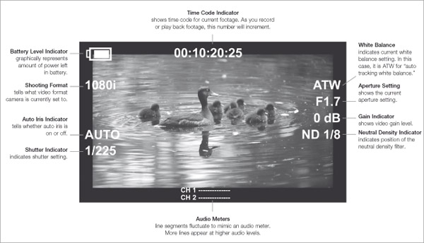
Modern cameras also provide a great deal of other information to the camera operator through the viewfinder (see Figure 5.19). By superimposing information over the picture on the viewfinder monitor, cameras provide information about the current settings of the controls. For example, visual indications in the viewfinder may show how filters, white balance, and gain controls are set (see below). The viewfinder also may provide visual warnings to the operator for such problems as a low battery or insufficient lighting. In addition, most professional cameras have a zebra stripes setting that indicates overexposed portions of the picture in the viewfinder. These bright parts of the screen are indicated with a black-and-white striped pattern (hence the name) superimposed over the video. The zebra stripes feature is useful for being able to quickly tell whether parts of the picture are overexposed.
Finally, a tally light, sometimes located on the front side of the viewfinder, tells the talent/subject that the camera is currently on the air or, in field-production situations, that the camera is recording.
Shutter Control
A shutter control, found on many video cameras, allows you to mimic the effect of varying the shutter speed on a still camera. The shutter on still cameras is normally a mechanical “door” that opens momentarily when a picture is taken, exposing the image sensor to light from the lens for a given period of time. The length of time the shutter is open is normally measured in fractions of a second, such as 1/30, 1/500 or 1/1,000; the higher the denominator (second number) in the fraction, the less time the shutter is open and the faster the shutter is said to be. On video cameras, the shutter is usually not mechanical, but the concept is still the same.
If you don’t specifically set the shutter speed, the camera will simply shoot in “normal” shutter mode, which sets the shutter to be open half as long as a single frame of video. For example, if you are shooting at 30 frames per second, the camera will set the shutter to 1/60 of a second (since each frame lasts essentially 1/30 of a second). The majority of the time, this is how you will want the shutter to behave. However, setting the shutter to a faster or slower than normal speed can create interesting effects, especially for subjects involving motion. If you set the shutter to a slower rate, say 1/30 or 1/15, it will tend to make moving objects more blurred in individual frames, and in some cases that will create the effect of smoother motion. On the other hand, setting a fast shutter speed, such as 1/500 or 1/1,000, will make moving objects appear crisper in individual frames, which can create a slightly “jumpy” effect when the video is viewed at normal speed. However, if that same video with a fast shutter is played in slow motion, the lack of blurring of individual frames will make the moving object appear much clearer. For example, if a fast shutter is used to shoot the blades of a spinning fan, the slow motion footage will make the blades of the fan appear more crisp and clear. For this reason, cameras shooting sporting events are often set for high shutter speeds so that slow motion replays will look better. One consequence of high shutter speeds, however, is that the camera will require more light; thus, the iris may need to be opened more to compensate.
Filters
Some professional cameras designed for both studio and field use have a built-in filter system to compensate for color temperature differences between indoor and outdoor lighting (see Chapter 6). Typically, a camera has filters for three different lighting conditions: (1) tungsten studio lamps and sunrise and sunset; (2) bright outdoor light; and (3) clouds or rain. If the camera is kept in a studio, there is no need ever to change the filter setting; the studio position is always the correct one.
If the camera is taken outside, the filter disk should be changed to one of the other filters (unless you are shooting during sunrise or sunset). These are both orange to compensate for the more bluish outdoor light. The difference between the bright outdoor filter and the cloud filter is the amount of neutral density (ND) that is mixed with the orange filter. Neutral density filters are designed to limit brightness without adjusting color. The ND #1 filter allows one-half the light to pass through, while ND #2 and ND #3 allow one-quarter and one-eighth, respectively. The filter for bright light has more neutral density than the one for cloudy conditions. Sometimes, other filters are part of the filter disk, or they are added to the front of the lens. For example, a soft contrast filter is used to create a fuzzy effect, and a star filter gives a star effect that radiates from bright spots on the screen.
White Balance
The white balance control establishes the correct color balance by electronically adjusting the red, green, and blue components of the signal so that pure white looks pure white. Since different types of lighting have different characteristics, some types of light may produce a bluish or reddish tint if no compensation is made. White balance adjusts for these different conditions.
Depending on the camera, the proper white balance can be set and maintained in several ways. Most cameras have an automatic white balance control that continuously tracks lighting conditions and adjusts the white balance accordingly.
Some cameras have one or more preset white balance settings that allow the user to select a preadjusted white balance setting for specific lighting conditions. On these cameras, the presets may be labeled with the lighting situation (e.g., indoor). Perhaps the safest way to ensure proper white balance, however, is to set it yourself. To do this, set the camera to manual white balance, and position a pure white object in front of the camera lens. Then, press the appropriate button on the camera to set white balance. Normally, you will need to hold the button for a second or two, and the camera will give an indication in the viewfinder that proper white balance is set. The disadvantage of using manual white balance, of course, is that you must constantly be aware of changes in lighting conditions and reset white balance as appropriate.
Camera Control Unit
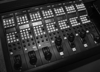
A camera used in a studio environment usually has a separate camera control unit (CCU). The CCU is mounted in the control room, connected to the camera body by special cabling (see Figure 5.20). The CCU allows the camera to be precisely calibrated so that it will produce quality video, a process called setup or shading. This calibration is usually performed by a technician and will likely be done before each production session. In addition to initial setup, the CCU also allows adjustment of the camera from the control room during the production if necessary.
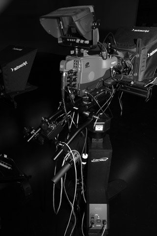
Prompter
As discussed in Chapter 2, a prompter is a device that displays the script on a monitor in front of the camera lens (see Figure 5.21). This allows talent to read the script while looking at the camera. The prompter system consists of
- the prompter unit mounted on the camera
- a computer connected via cabling to the prompter unit that stores the scripts and provides the input signal for the prompter
- a controller.
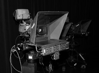
Once the script is entered into the prompter computer, it can be displayed on the prompter unit. During the production, the prompter operator will use the controller to select the proper speed at which the script will scroll on the prompter. Most systems allow the script to be backed up in case a scene needs to be shot again. On some systems, the computer’s keyboard or mouse is used instead of a separate controller, and in other cases the talent may control the prompter using a foot-operated switch.
DSLR and Smartphone Cameras
As noted at the beginning of this chapter, “traditional” video cameras have been joined by DSLR and smartphone cameras as legitimate tools for video production. Although neither type of camera is designed to be as integrated into the studio production environment as studio cameras, they can still be used in studio production situations. However, it is normally in field production situations that DSLRs and smartphone cameras can be most effective.
DSLR Cameras
Digital SLRs are the modern version of SLR cameras that for several decades were used to shoot still pictures on 35 millimeter film. SLR stands for single-lens reflex, and it refers to the fact that the image exposed to the image sensor (or the film, in the case of earlier cameras) is the same image that is seen through the viewfinder. SLRs (digital and film-based) have long been the choice of professional photographers for shooting still pictures, and now DSLRs are increasingly being used for video as well.
The main advantage of DSLRs for shooting video is that they have larger image sensors than most dedicated video cameras. This means that DSLRs can produce very sharp images and that they allow you to frame shots with a much narrower depth of field. This creates, in some cases, a more artistic or cinematic look to the video. Also, since a wide variety of interchangeable lenses are available for a given DSLR camera, you can swap lenses depending on the shooting situation. For example, you might use a very wide macro lens to shoot the close-up detail of a flower, then switch to a zoom lens to get a shot of a bird high up in a tree. Finally, DSLRs can be very good for shooting in low-light conditions.
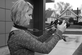
But there are also challenges to shooting video with DSLRs. Since they are designed primarily for shooting still pictures, the viewfinder is located on the back of the camera, and the controls are positioned to be operated while holding the camera in front of your face (see Figure 5.22). There are various attachments and mounting rigs that can overcome these issues, as discussed in Chapter 12. Another challenge is that DSLRs do not record very good audio with their built-in microphones, and they lack XLR connectors to attach high-quality external microphones. For this reason, most video productions with DSLRs use an external audio recorder to simultaneously record audio onto separate media. The video and audio portions of the footage can then be combined during editing. Finally, because of the way the shutters operate on DSLRs while shooting video, a rolling shutter distortion can happen when either shooting rapidly moving objects or while panning the camera quickly. This distortion can introduce a wavy effect to certain parts of the frame or an overall skew to the shot.
Despite these issues, an increasing amount of video production work—especially field production—is being done using DSLR cameras. The main operational controls are the same as traditional video cameras, although DSLRs also offer an ISO control that allows you to set the light sensitivity of the image sensor. Higher-numbered ISO settings (such as 2,000 or 3,200) increase the sensitivity, allowing you to shoot in lower light; however, higher ISO settings also introduce distortion (often called “noise”) in the image. Lower-numbered ISO settings (such as 50 or 100) will provide the clearest pictures, but will also require the greatest amount of light. Thus, achieving proper exposure for video on a DSLR camera involves the interplay among shutter speed, aperture setting, and ISO setting.
Smartphone Cameras
Although many modern smartphones can shoot excellent-quality video in certain situations, their main advantage is their ubiquity and their small size. Almost everyone has a smartphone these days, and most people carry them wherever they go. That means unplanned events—such as a fire or emergency plane landing—can be captured on video easily. In addition, their small size means that they can be hidden or positioned unobtrusively in small spaces.
Like DSLRs, however, smartphones were not designed primarily for shooting video. Thus, they have shortcomings with regard to lens quality, connectivity, and usability. The lenses on most smartphones are very small, and can perform zooms only digitally, not optically. Also, more smartphones have only a 1/8 inch audio jack, meaning professional quality XLR mics cannot be plugged directly into them. Finally, all of the operational controls (with the exception of the record and zoom functions) need to be operated through the use of screen-based menus rather than with dedicated physical controls. However, given the popularity of smartphones, a number of companies make products that can overcome some of these issues. For example, lens attachments can allow macro or wide-angle fields of view, and higher-quality microphones and XLR adapters are also available.
Camera Mounting and Movement
Efficient use of the camera depends upon several interdependent factors during a production. The first of these is simply the position of the camera in relationship to a subject (or multiple subjects in wide-angle shots). The camera reveals the front, side, or top of the elements in the picture according to where it is placed. A second factor involves changing the direction in which the camera is aimed to reveal different subjects.
There also can be a continuing change in the point of view of the camera as it is moved to reveal different aspects of a subject or sequence of subjects. This movement also can involve changes in the elevation of the camera, especially for artistic effect. The effectiveness of these operations is dependent upon the hardware that provides movement and support for the camera.
Camera mounting equipment makes provisions for the use of ancillary devices attached to the camera, most notably a prompter, as discussed previously. In some cases, a video monitor or clock also may be attached to the camera mounting apparatus.
Camera Head Movement
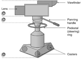
Figure 5.23 shows the basic parts of a studio camera unit, including (a) the video components of the camera itself; (b) the mounting head containing the equipment used for movement of the camera; and (c) the camera mount that controls floor movement of the entire unit.
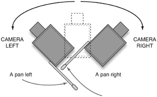
Shot changes involving vertical and horizontal camera movement are fundamental to video production (see video examples on the Video Production website). A horizontal movement to the left or to the right is known as a pan. (See Figure 5.24.) When told to “pan right,” the operator moves the camera lens in the direction of his or her right hand. This is the reverse of stage movements, which are given from the standpoint of the performer looking out toward an audience.
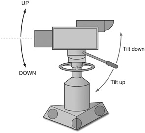
An up-and-down movement of the camera is called a tilt. The lens end of the camera is moved up or down by pivoting the body of the camera on its mount to view elements at different elevations of the set. (See Figure 5.25.) Both pans and tilts are accomplished by moving the pan handle (or handles) at the rear of the camera mount.
Camera Mounts
While both pans and tilts can be accomplished by simply moving the camera head, any change of camera position, whether done as an on-the-air movement or simply for the purposes of changing the framing of a shot, is accomplished through movement of the camera mount.
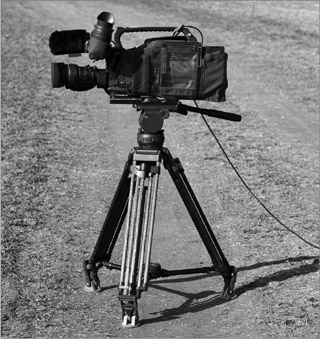
The simplest and least expensive camera mount has traditionally been the tripod. When used in a studio environment, this three-legged stand is usually fastened to a dolly base consisting of three casters. The casters can either rotate freely, which facilitates quick and easy movement of the camera in all directions, or be locked into an unmovable position, resulting in a steady camera unit.
The field model tripod, illustrated in Figure 5.26, has a crank-operated elevation adjustment that can be used to raise and lower the camera—although not smoothly enough for the move to be used on the air. Many tripods have no adjustment for height other than the laborious process of mechanically adjusting the spread of the tripod legs. Thus, there is no way to achieve any elevation change during an actual production. The tripod, however, is lightweight, and most models are readily collapsible. This makes the tripod a desirable camera mount for most field productions. The ever-decreasing size of portable cameras has made the monopod, which is essentially a one-legged tripod, an even lighter option for some field work. However, the monopod is really useful only for maintaining steady shots, not for attempting pans, tilts, or other movements.
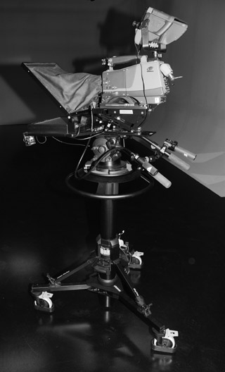
The pedestal mount shown in Figure 5.27 has been the standard for studio production since the beginning of television. Its distinctive feature is the central pedestal that can be raised or lowered with the assistance of counterweights or air pressure. It also has a steering ring that controls all three casters in a synchronized manner to allow smooth on-the-air camera movements across the studio floor. The ease and steadiness in camera movement have made the studio pedestal a must in any big studio production.
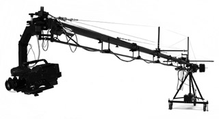
When more-pronounced changes of position and elevation are called for, they are accomplished through the use of specialized mounts, such as the crane mount (shown in Figure 5.28) and the smaller crab dolly. With the crane, considerable camera movement over a wide vertical and horizontal range is possible. Inherited from the film industry, the crane is the largest and most flexible type of camera mount and comes in a variety of sizes. The camera itself is mounted on a boom arm that can be moved vertically or laterally without moving the crane base. Depending upon the model, the length of the arm extension is 10 to 15 feet for studio models and much more for a few special field units. For everything from rock concerts to Olympic coverage, the moving crane shot has become an indispensable part of the visual language of television.
Camera Mount Movements
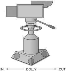
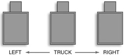
One of the most obvious changes in picture framing is accomplished by moving the camera closer to or farther away from the subject. This is referred to as dollying the camera, and it produces a dolly shot. (See Figure 5.29.) Lateral movement of the camera and its mount is known as trucking. A change of picture is accomplished as the camera trucks right or trucks left, because the camera moves sideways without panning to the right or left. (See Figure 5.30.) In the field, dollying and trucking movements normally cannot be attempted unless special tracks have been laid down to facilitate smooth, level movement. Usually, such movements are set up only for ambitious productions like high-budget dramatic programs or major sporting events.
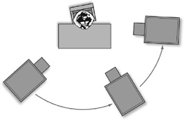
A follow shot can use both the trucking and the dollying techniques. Here, a camera moves with the subject and maintains a constant distance from it, while the background is seen to move past in a constantly changing panoramic sequence. An arc shot is another variation of a trucking movement. The camera circles around the stationary subject to reveal different aspects of the subject. (See Figure 5.31.)
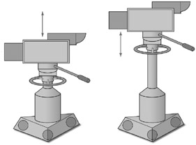
Another move uses studio camera pedestals to facilitate a slight change in camera height. In this case, the word pedestal is used as a command, as when the camera operator is asked to “pedestal up” or “pedestal down.” (See Figure 5.32.) In larger studios where crane mounts or crab dollies are used, other effective movements are also possible. Craning, or booming (up or down), involves raising or lowering the crane or boom arm. The effect is similar to a pedestal movement, except that much greater vertical distances can be covered. Another kind of motion is the arm move. With a large crane, the boom arm or crane can be moved left, right, up, or down or any continuing combination of these, while the base remains stationary. With both the crane and the crab mounts, the camera operator maintains control over the angle and tilt of the camera throughout all these moves.
All these movements are difficult to use on-air when a zoom lens is at high magnification (a narrow angle). The slightest unsteadiness during the camera movement is exaggerated, because the long lens, while magnifying the subject, also magnifies the shaky camera movement. To a lesser extent, the same problem is apparent with panning and tilting movements.
Handheld Cameras
For some types of production, especially field work, the use of handheld cameras is common. Shoulder-supported professional units and consumer-oriented, palm-sized camcorders facilitate situations where the camera operator effectively becomes the camera mount.
Since no mount is used, the camera operator is not constrained in either time (by having to pick up and move a camera mount) or space (by having to shoot only from locations where a mount can be set up). The use of a handheld camera can provide greater flexibility and thus is considered indispensable for “reality-based” television, news, sporting events, and concerts.
However, it is important that the operator of a handheld camera be able to keep the camera steady and avoid shaky shots and jerky movements. Some techniques for doing this are discussed in Chapter 12.
Robotic Camera Control
The use of robotic camera control in news, public affairs, and sports programs is increasing. In these systems, the zoom, focus, and camera mount movements of one or more cameras can be controlled by a single camera operator. (See Figure 5.33.) Sophisticated camera moves (such as a simultaneous arc shot, pedestal up, and slow zoom in) can be programmed to execute automatically during a show. In robotic systems, the camera is mounted on a pedestal with a series of motors that control pan, tilt, and dolly movements. The camera operator can then control a number of cameras from the control room and even perform picture adjustments on individual cameras.
Drones
The availability of drones has created another opportunity for camera mounting and movement. Generally speaking, a drone is any kind of unmanned, remote-controlled aircraft, and large drones have been used in military applications for many years. Now, smaller drones are available for consumer and professional use, and among the most popular applications for them is shooting video. (See Figure 5.34.) A small camera can be attached to a drone, allowing a skilled operator to create a wide variety of shots previously possible only with the use of a helicopter. Drones come in various sizes and types, ranging from under a hundred dollars to thousands of dollars. Some drones are controlled by a simple remote, while others can be controlled by a smartphone application.
The Federal Aviation Administration (FAA) has implemented rules regarding drones, and you should familiarize yourself with them before flying (see www.faa.gov/uas/). Before flying a drone for commercial purposes, you must have a Remote Pilot Airman Certificate. There are also regulations regarding the size of the aircraft, flying at night or over people, and maximum altitude.
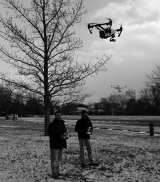
Figure 5.34 Drones used to shoot video. (Courtesy of Toledo Aerial Media, www.toledoaerialmedia.com)
Field of View
The camera operator should be familiar with the terms designating the size of the shot desired or the field of view, as discussed in Chapter 4. Generally, most television shots can be related to several basic categories, as shown in Figure 5.35. These shot designations are to some degree relative to their use and the artistic concepts of the director or camera operator. What is a long shot for one dramatic segment could be considered a medium shot in another situation.
The Long Shot (LS)
The perspective of the long shot, also referred to as the wide shot (WS), is far enough away from a person that his or her entire body and quite a bit of the surroundings are included. Often, the performer’s facial features are indistinct at this distance. This is also known as an establishing shot when used in the beginning of a production (or segment), because it relates those people involved in a program not only to each other but also to the setting and circumstances of that program. In drama and in other applications, these wider shots are also necessary whenever people move from one part of the set to another. The wide shot can be used as a closing shot to signal a pulling back from the action as a program or segment comes to a close.
Sometimes, you might want to establish a panoramic scene or cover the sweep of action with a very wide shot. If characters are so far away that they are hardly identifiable as specific individuals, the shot can be labeled an extreme long shot (ELS or XLS).
The Medium Shot (MS)
As discussed in Chapter 4, a medium shot of a person includes most of a person’s body or perhaps those of two people. The medium shot is the basic shot in standard television production. It is used to convey much of the dialogue in drama and most of the action in talk shows, game shows, variety programs, and many other studio productions.
The Close-Up (CU)
The close-up establishes a sense of physical intimacy that can probe the individual and personal aspects of what a program is communicating. In many dramatic situations, the close-up is the only way to get insight into the emotional state of a person or performer. A close-up shot may, of course, be used to view objects as well as people. It may be a close-up of some item that has importance to the narrative of a drama. In a commercial, it may be the product that is being advertised.
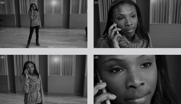
The extreme close-up shot is most often used to intensify the emotion of a dramatic situation or musical performance. When these shots are used carefully, they can add the right artistic effect at the right moment. While the difference between the close-up and extreme close-up is open to interpretation, the essential distinction is that the extreme close-up normally calls attention to itself. While a close-up of a person’s entire face will not normally call special attention to itself, for example, an extreme close-up of a tear rolling down that person’s face will.
Picture Composition
Beyond understanding how cameras operate and how different types of shots are identified, it is important to understand some of the aesthetic disciplines of shooting video. As we discuss framing, headroom, lead room, depth composition, angle of elevation, balance, and movement, keep in mind that the various “rules” that have evolved as part of the grammar of the medium should be considered guidelines. As with any artistic effort, a new approach is always valid if it communicates something to an audience. Once you understand the rules, you can modify or even ignore them as long as you do so intentionally and for a legitimate artistic reason.
Framing
Television directors have developed simple terminology to describe the basic dimension of a shot to the camera operator. The scope of a shot is described in terms of that portion of the body that is to be cut off by the bottom edge of the picture. Thus, a full shot, thigh shot, or chest shot quickly communicates the desired framing of the person or persons in the picture.
Equally useful are the terms single, two-shot, or three-shot, which describe the number of people to be included in the shot. Other descriptive labels have evolved to specify certain kinds of desired shots. For example, an over-the-shoulder shot (O/S) might be called for in a situation when two people are facing each other in a conversation (such as a dramatic scene or an interview program). This is a shot favoring one person (who generally is facing the camera) framed by the back of the head and shoulder of the person whose back is to the camera.
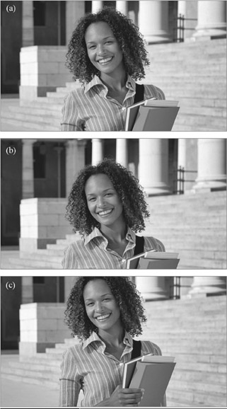
Headroom
An important discipline for all camera operators is to consistently maintain an appropriate amount of headroom. This term refers to the space between the top of a subject’s head and the top of the frame. When this distance is not observed, the results can be distracting. (See Figure 5.36.)
It is especially important that headroom distance be uniform among all cameras on any production. A helpful guide for shot consistency is to place the eyes of a subject at the level of an imaginary line approximately one-third of the way down from the top of the picture. In close-up shots, the framing is best with the eyes slightly below the line; in wider shots, they should be slightly above the line.
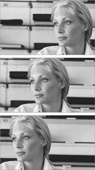
Lead Room
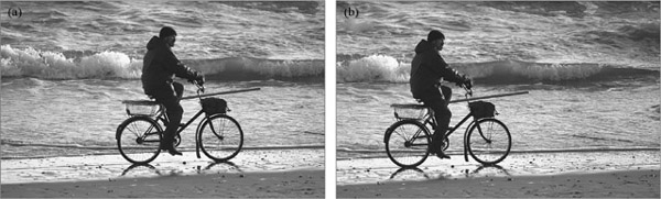
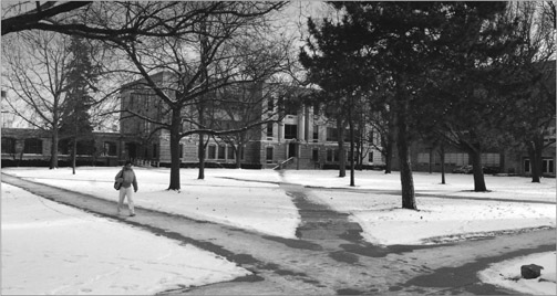
When speakers or performers directly address the camera, they generally are centered in the frame, unless a foreground object or over-the-shoulder visual effect is to be included in the frame. When a subject in a close-up shot is speaking to another with his or her head turned toward that person, the framing is much more attractive if there is an added amount of lead room (which is also referred to as talk space, eye space, look space, or nose room) on the side of the frame to which the person has turned. (See Figure 5.37.) By the same token, a distracting, crowded effect is created if the framing has the face of the subject too close to the frame edge. The concept of lead room applies even more strongly to moving subjects. If a person (or animal or object, for that matter) is moving laterally across the screen, it is important to allow lead room in front. (See Figure 5.38.)
Depth Composition
Despite the advent of 3D, most video production is still transmitted in two-dimensional form. To simulate some feeling of depth, the director has a number of options that involve lighting, camerawork, the set, and the placement of performers. One method is to make sure that the performers are separated from the set in the background both by their physical positions and by the constructive use of lighting. In this situation, it is important to portray something familiar like the interior of a room or office to provide a feeling of scale or perspective. If a plain or abstract background is used, the viewer has no yardstick against which to gauge the distance from the subject to background.
Foreground objects can add significantly to the feeling of depth. By framing some nearby objects off to one side or along the bottom of the picture, the subject in the background is placed in greater relief. Care must be taken, though, not to force an unnatural effect for its own sake, as this will undoubtedly appear contrived.
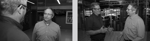
Whenever possible, depth composition can be achieved with the arrangement—or blocking—of talent. If several people appear in a scene, try to arrange them so that some are closer to the camera than others. In a two-shot, an over-the-shoulder shot as a rule is preferred to a flat two-shot of a double profile. (See Figure 5.39.) A feeling of depth also can be achieved by careful use of angles. If a shot calls for someone to sit behind a desk, the camera can get a much more interesting shot by shooting the desk and subject from an angle. (Of course, the dramatic context might call for a formal head-on shot of a character such as a judge or a stern employer.)
Angle of Elevation
For the most conventional composition, the camera should shoot at an angle relatively level to the subject. Generally speaking, try to place the camera lens at eye level with the talent when he or she is standing. When seated, however, this means that you must move the camera down so the camera is as low as the talent. To achieve this level angle, most “talk sets” (news programs, interviews, discussion shows, talk shows) are staged on a raised platform or riser. If you cannot avoid shooting down into an interview or discussion set, the steep angle can be minimized somewhat by using a longer lens setting and dollying back away from the set. The farther back you can get, the less steep the angle will be.
There are times when, for dramatic effect, you will not want to shoot the talent at a level angle. To portray an actor as being overwhelmed, submissive, or downtrodden, you might shoot the actor from a higher elevation. Shooting from a high angle implies control and dominance over the individual. On the other hand, if you want to give a character power and authority, you might shoot that actor from a low angle. By placing the viewer in the lower position, you endow the character with force and strength. (See Figure 5.40.)
Balance
Most beginning camera operators have a tendency to place the most important element in a shot directly in the center of the picture and then balance other picture components with elements equidistant from the center. This kind of mechanical or symmetrical balance can lead to very stiff, dull, formal pictures. A more dynamic composition is asymmetrical balance, wherein a lightweight object some distance from the center of the picture can balance a heavier object closer to the center (similar to a seesaw with a light person at the end of the board balancing a heavier person seated close to the center). Another way to avoid centralization of picture elements is to think in terms of the rule of thirds. Imagine the television screen divided horizontally and vertically into thirds. Placing pictorial elements at the points where the lines intersect results in a more pleasing balance than centering elements symmetrically, as shown in Figure 5.41.

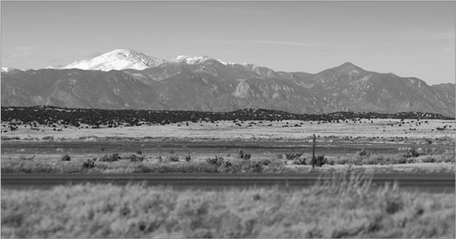
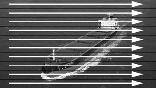
As noted, the wider 16:9 aspect ratio more closely mimics the natural human field of vision and can be particularly compelling for landscape shots and other horizontal views, as shown in Figure 5.42. However, vertically oriented subjects present more of a challenge. This problem can be remedied by framing the shot so that other elements fill these empty spaces in the sides of the frame, or by shooting the vertical object from a low angle, or both, as shown in Figure 5.43.
Other Composition Problems
Other compositional problems may arise when cameras are used outside the studio. For example, when shooting a close-up or medium shot of talent, avoid framing the person so a sign, telephone pole, or other object appears to grow out of his or her head. (See Figure 5.44.)
Be sure that the camera is level when shooting. A misadjusted tripod (with one leg extended farther than the others, for example) will tilt the camera. Consequently, the horizon line in your shots will not be level, creating the impression that people and objects are about to “fall” out of frame. (See Figure 5.45.)
Production Techniques
In any production situation, a few standard procedures will help you be an effective camera operator. The first of these is to become familiar with the camera’s operational controls as much as possible before the production begins. Of course, the only way to learn some things is through the trial by fire that is real production. Nevertheless, practice using the motorized zoom control, try doing a few tilts and pans, and practice focusing, for example, beforehand.

You should also develop the habit of checking the camera before the production starts to make sure it is in proper working order. It is important to put a camera through its paces to make sure all of its components are functioning properly. A lot of this will occur as you go through the process of familiarizing yourself with the camera, but you should do other things as well, such as checking connectors and making sure the picture controls are properly adjusted.

When using a video camera in the field, it is a good idea to record some test footage before the production begins to be sure the camera is operating properly.
It is also a good idea to practice specific camera moves you know you will have to do during a production. Before the show, you may be given a shot sheet listing the shots you will be responsible for getting during the production. If one of these, for instance, is a smooth zoom out and tilt up from the logo on a desk to the talent sitting at the desk, you can practice this move before the production begins.
Finally, once the production begins, remain alert and ready. If you’re working in a studio environment, you will likely wear a headset so you can talk with the director and other personnel through the studio intercom system. Be ready to execute the director’s commands and to provide feedback if the director asks for it. In some situations, such as live talk shows, the director may occasionally ask you to look for good audience or guest reaction shots, for example.
Many specific operational procedures are established by the production facility. In your classes, the instructor will establish operational procedures for the cameras and other equipment, including what controls you should not operate. Learning and properly following these procedures is itself an important production technique. Similarly, it will be important to follow these same kinds of procedures when you become a working professional.
Focus Points
After reading this chapter, you should know …
- The basic scanning processes used to create video.
- The role of hue, saturation, and luminance in creating video color.
- How a camera produces video signals.
- Lens characteristics and principles of len operation.
- The theory and operation of zoom lenses.
- Common camera controls and how they are used.
- How different types of camera mounting equipment are used.
- Basic camera shots and how they are used.
- Basic principles of picture composition, including framing, headroom, lead room, angle of elevation, depth composition, and balance.
- Basic camera operation techniques.
Review
- What are the main differences among ATSC formats in terms of resolution, scanning, and frame rate?
- How do the three aspects of color (hue, saturation, and brightness) combine to create specific colors?
- What are the basic aspects of lens design and how do they affect shots?
- How do different camera mounts affect camera shots? What types of shots are possible with each type of camera mount?
- Discuss the guidelines of picture composition. Why is each guideline relevant, and how does each serve to make a better picture?
On Set
- Practice shooting footage using the guidelines for shot composition discussed at the end of this chapter. Intentionally violate some of the principles to see the negative effect. Can you think of times when these principles can be violated without adverse effect?
- Practice manipulating the depth of field of a scene of two people talking. First, set up the shot so that both the subjects and the background are in focus, then set up the shot so that the background is no longer in focus. How do the two shots differ in the emphasis placed on the main subjects of the shot?
Notes
1The complete specifications for the NTSC format were 640 columns by 480 lines with a frame rate of 30 fps using interlace scanning.
2Technically, the focal length of a lens is the measure from the optical center point of the lens (when it is focused at infinity) to a point where the image is in focus. Focal length is measured in either millimeters or inches (25.4 millimeters being equal to 1 inch).