Audio is an extremely important element of a TV program, often credited with providing 80 percent of the information. Viewers readily pick up any mistake with audio, especially the lack of sound, which can lead them to change the channel to make sure their set is still working. If they get distracted with another program and don’t come back, that is a lost viewer—something stations and networks definitely don’t want.
The disciplines and techniques of production are applicable to the field of audio. For example, knowing the steps needed to connect a microphone so that it functions through an audio console is a matter of applying several basic techniques. At the same time, the care with which the operator works to test the quality and loudness of that mic is very much a matter of individual discipline.
When you are operating audio equipment, you must constantly think ahead to your next actions. Which audio fader will you raise next to bring up the sound from the breaking news in the field? How loud should the music be under the host? How quickly will the microphone boom need to move as the talent exits?
This chapter will enable you to build both audio techniques and disciplines and to understand both the technical and the creative aspects of sound. The equipment discussed in this chapter models the basic control functions discussed in Chapter 1. The microphones transduce, the cables and connectors channel, the outboard equipment records and plays back, the audio board selects and alters, and the speakers monitor.
Microphones
Microphones pick up sounds (voices, live music, etc.) and convert them into electrical audio signals, a process referred to as transducing. There is no single perfect microphone for doing this. You need to select the microphone that is best for what you are recording. A microphone that makes a male announcer’s voice sound mellow might be ineffective for recording a flute solo. A microphone that works well in the controlled environment of a studio might not be rugged enough for a field shoot. A singer’s favorite microphone is probably inadequate for picking up the laughter from a sitcom audience. To take care of a variety of situations, microphone manufacturers make many different microphones that vary in such qualities as frequency, amplitude, pickup patterns, construction, and positioning possibilities.1
Frequency
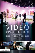
Microphones are affected by the frequency of sound waves. This is the rate at which the waves move, which is measured in hertz (also called cycles per second).2 For example, if the sound waves are produced at a constant rate of 440 hertz (cycles per second), the result is the musical tone of A above middle C on the piano. Bass (low) sounds have fewer cycles per second than treble (high) sounds; conversely, treble sounds have a higher frequency than bass sounds.3 (See Figure 7.1.) Men’s voices have frequencies around 500 hertz, while women’s voices are more likely to range at or above 1,500 hertz. We hear sound frequency as pitch: The higher the frequency, the higher the pitch. Humans with good hearing can discern a range of frequencies from a low rumble at 20 hertz up to a possible high of 20,000 hertz (1,000 hertz equals 1 kilohertz, which is abbreviated kHz, so 20,000 hertz could also be called 20 kHz).
The main frequency of a sound is called the fundamental, but sounds also have a number of higher-frequency overtones. While these overtones (also known as harmonics) are produced at much lower loudness than the fundamental tone, they are very definitely picked up by the human ear. These overtones vibrate at different degrees of loudness according to the resonating qualities (timbre) of each voice or musical instrument. A trumpet has a different sound from a clarinet, even when it is playing the same note, because its overtone pattern is very different from that of a clarinet. Likewise, two women’s voices sound different even though they are roughly the same frequency.
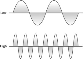
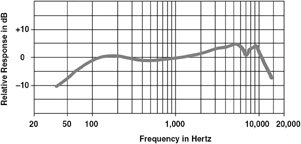
Microphones can be manufactured to pick up different ranges of frequencies, a trait referred to as their frequency response. Microphone manufacturers often provide charts to show frequency response characteristics so that you can choose the mic that is best for your particular application. (See Figure 7.2.) A mic that picks up all frequencies equally well is said to have a flat frequency response. One that picks up the human voice better than higher or lower frequencies is said to have a speech bump, because the line rises starting at about 300 hertz and then falls off by 3,000 hertz. Some mics pick up certain frequencies better at different positions. For example, the Shure mic shown in Figure 7.3 picks up 125-hertz frequencies but not 1,000-hertz frequencies toward the back of the mic. If you are producing a discussion program, you can use mics with more limited frequency response than those used in producing a musical show, where all the overtones are particularly important.
Amplitude
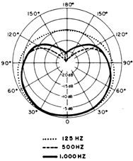
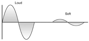
Another element that microphones take into account is amplitude. Amplitude refers to the strength or volume of the sound. We hear this wave characteristic as loudness. A 440-hertz “A” piano note played loudly produces a higher amplitude than that same note played softly. (See Figure 7.4.) Amplitude is a measurement of the sound pressure caused by the audio source. The louder the sound, the greater the sound pressure of the sound waves moving through the air.
Amplitude is measured in decibels (dB).4 A whisper is about 20 dB, and a gunshot is about 140 dB. The range of loudness that a microphone or other equipment can handle is referred to as its dynamic range. A high-quality piece of hardware with a wide dynamic range can record a whisper so it can be understood and a gunshot so it is not distorted.
Pickup Patterns
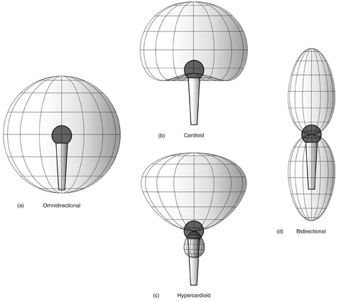
Microphones can be designed so that they pick up sound from different directions. (See Figure 7.5.) Some are omnidirectional, meaning they pick up sound from all directions. They are good for recording crowd noises, audience reactions, and sounds from a group of people in a circle. Other mics are unidirectional, meaning they pick up sound in one direction. Unidirectional mics are also called cardioid mics because they record sound in something of a heart-shaped pattern, picking up sounds from straight on and also a little to the sides. Cardioids are effective when you want to record sounds in one direction while excluding sounds from other directions. They are the most commonly used TV studio production mics because they pick up talent voices without picking up the background noise of cameras moving in the studio.
Some mics have very narrow pickup patterns, usually referred to as supercardioid, hypercardioid, or ultracardioid (or those same prefixes added to -directional). They can pick up sound from a distance, but they have a progressively smaller pickup area than a cardioid mic. They are less likely to be used in a studio than they are in the field where circumstances such as breaking news prevent close miking. Bidirectional mics pick up sound from two sides, making them useful if two people directly face each other.
A few mics are manufactured so that they can switch from one directionality to another, perhaps cardioid to omnidirectional. For some of these mics, you unscrew a top element that is cardioid and screw on another element that is omnidirectional. In contrast, a zoom mic contains electronic circuits that allow you to change gradually from cardioid through ultracardioid.
Whatever a mic’s specifications, the general rule is that the longer the mic, the more directional it is. A directional mic needs holes, called ports, along the sides to distinguish between reflected sound waves that hit the mic from the side and are filtered out and direct sound waves that hit the mic straight-on and pass through to the transducing element. The longer the mic, the more ports it has and the more directional it is. Small mics with no side ports are omnidirectional.
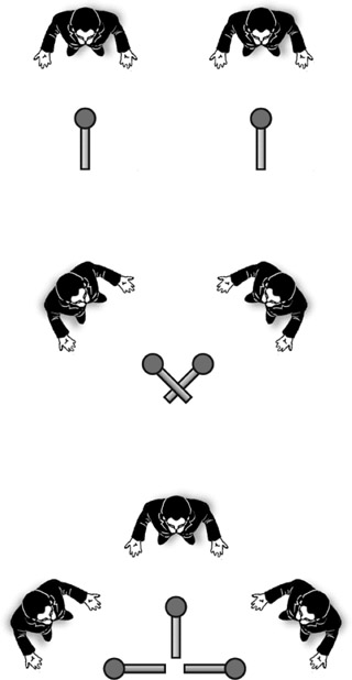
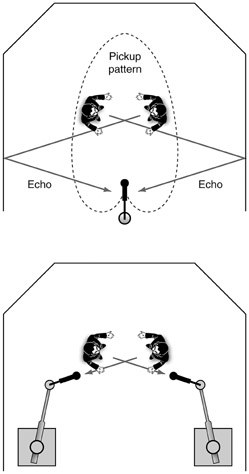
Many programs are recorded and distributed in stereo rather than monaural. There are a number of ways to accomplish stereo recording.5 In one pattern, called “A-B” or split-pair miking, two microphones (A and B) split the recording, picking up the sound much as your ears do, with a left and a right microphone placed several feet apart (they have to be placed far enough from each other to avoid phase cancellation—refer ahead to Figure 7.33). In another pattern, called “X-Y” or cross-pair miking, two microphones are placed next to each other instead of apart, and they are crossed to form an X so they pick up sounds from the left and right, as well as each picking up sounds in the middle (the “stem” of an inverted letter “Y”). In yet a third pattern, called mid-side microphone placement, one mic picks up sound in the middle, and either two additional mics or one bidirectional mic pick up sound from the two sides. (See Figure 7.6.) Additionally, some single mics have multiple elements that imitate stereo miking patterns. They are not perfect, but they are simpler to set up and use than the multiple microphone techniques described above. (See Figure 7.7.)
It is also possible to record surround sound, so that the final sound can come from five to eight speakers located around the room. Surround sound 5.1 is an industry standard. Recording in surround can be quite complex6 and usually involves setting up arrays of cardioid and supercardioid microphones pointed at different spots around the circumference of a circle. There are also single-unit surround sound mics. (See Figure 7.8.) Miking for either stereo or surround sound is complicated when it involves multiple microphones, because mics placed too close to each other tend to cancel out each other’s audio (a problem called phase cancellation, which experienced audio engineers eliminate by “phasing” all the microphones in a studio or on location before shooting). For this and other reasons, stereo and surround are often created in postproduction, where the sounds can be manipulated more precisely.
Construction
When sound is transduced by a microphone, audible sound pressure waves, with their particular frequencies and amplitudes, move through the air and come in contact with the mic. The microphone housing collects and directs (and sometimes filters) the sound to an internal diaphragm. The diaphragm, in turn, connects to some type of transducing element that takes the vibrations of the diaphragm and turns them into corresponding, or analogous, electrical waveforms. These waveforms travel through the connecting cable to the hardware that amplifies, processes, and records the sound. The electrical signal coming from a mic is very weak; before it can be processed and recorded, it must be amplified many times over. In the case of an audio board or console, the amplifier is built into the circuit when the mic signal enters the mixer. In the case of a camcorder, the amplifier is built into the camera circuitry.
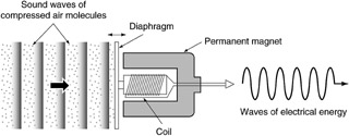
The transducing elements—the pieces that actually change sound-wave vibrations into analogous electrical waves—come in a variety of types, from aluminum ribbons in high-fidelity but sensitive ribbon mics to crystal rocks or other minerals in older, durable, but low-fidelity telephones. For TV and video production, two types of elements are most common: dynamic and condenser. Dynamic mics, also called moving coil mics, contain a magnet with a coil of wire (usually copper) attached to the diaphragm that moves inside the magnet. The sound waves cause the diaphragm and coil to vibrate within the magnetic field, and this sets up an electric current in the coil. (See Figure 7.9.) This transduced electrical signal is analogous to the original sound, retaining its amplitudes and frequencies. The magnet, coil, and diaphragm are fairly rugged, allowing a dynamic mic to tolerate rough handling as well as temperature and humidity extremes, so it is often the choice for field production.
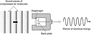
In contrast, a condenser microphone has a movable diaphragm connected to an electrically charged backplate. The two elements form a capacitor, which generates voltage as the diaphragm and charged plate move back and forth in response to sound-wave pressure. (See Figure 7.10.) This structure produces high-quality sound and also allows the mic to be small (a capacitor instead of a moving wire coil). While a dynamic mic generates its own charge with its moving coil, a condenser unit must have a source of electricity to function: It has to charge the backplate. One source of electricity is a battery: a battery or batteries in the mic handle, or a portable battery pack attached to the mic. Another source of electricity is phantom power: The audio console (if so equipped) sends a small current to the mic through its connecting cable. Some condenser mics have permanently charged backplates for another option. A condenser mic is not quite as durable as a dynamic mic, but it has a slightly better frequency response. Some additional microphones, called dual-element mics, have both dynamic and condenser mic elements mounted side by side so that the audio operator can switch from one to the other if the need arises.
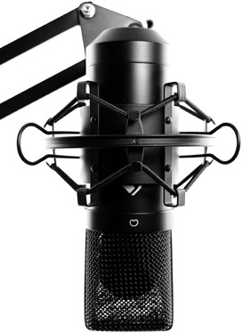
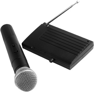
Another element of a mic’s construction is whether it is intended to be used in a wired or wireless configuration. Any microphone (dynamic, condenser, or other) can be either wired or wireless. The difference is not in how the sound is picked up but rather in how it is delivered. Wired mics have a connector that enables them to be attached to a cable that carries the signal from the mic to wherever it needs to go. (See Figure 7.11.) A wireless mic has a small antenna that sends the sound through the air to a small receiver using a radio frequency (RF), turning the unit into a sort of miniature radio station. The receiver is then connected to the wall outlet in the studio or to a circuit in the control room. (See Figure 7.12.) Wireless mics are used when the talent needs to move about and cannot be tied to a cable, such as a singer who also dances, a talk-show host who goes into the audience, or a reality star who is followed by a production crew. A downside of wireless mics is that they are subject to interference from strong electrical units (e.g., overhead power lines, heating and cooling units) and other nearby wireless devices (e.g., cell phones, wi-fi, short-wave radios, remotes). Water and sweat also reduce their signal strength.
Positioning Possibilities
Microphones—be they omnidirectional or cardioid, dynamic or condenser, wired or wireless—need to be placed somewhere on the set where they can pick up sound. For some situations (interviews, musical performers), it is acceptable for the microphone to be seen. For others (comedy, drama), the microphone needs to be out of sight or at least unobtrusive.
When a small, unobtrusive microphone may be seen, such as news, interviews, and talk shows, the mic is usually clipped to the performer’s clothing close to the mouth. These lavaliere (lav) mics, also called lapel mics (though they can be clipped to a tie, next to a shirt button, or, yes, on a lapel), are generally condenser mics because they need to be small. (Refer to Figure 7.12b.) They also have a short range so they pick up sound directly from the mouth and not from the overhead fans or other sources of white noise; for this reason, lavs are best placed 6 to 8 inches below the mouth. Typically, they are positioned slightly below the neck on top of a tie or blouse so they do not pick up any rustling noises from the clothes.
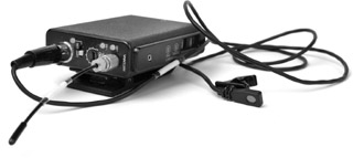
A lav mic is usually attached to a slightly bulky power supply (and integrated antenna if a wireless mic) that can be clipped to the back of a belt or waistband or hidden on a chair or other set piece. This unit, in turn, sends the signal along an attached cable (wired) or to a receiver (wireless), which then delivers the signal to its next destination (amp, mixer, recorder, etc.). It is best to put all the visible wires under the talent’s clothing so they do not show and so the wires move when the talent moves. Lavalieres have the advantage of being inconspicuous, but they can pick up the sound of only one person.
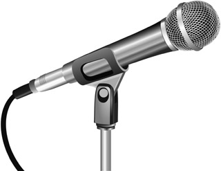
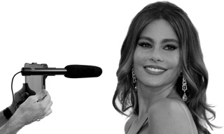
Larger, more conspicuous mics (refer to Figure 7.11) are often used for situations where the viewer expects to see someone using a mic. Sometimes, these mics are held by the talent and are referred to as hand mics—for example, a singer, a reporter interviewing someone, or a talk-show host wandering through the audience. Obviously, one mic can be used by more than one person, but anyone who is going to hold the mic should know how to use it so the sound does not fade in and out because he or she moves the mic too far away from the source of the sound.
The same microphones that are handheld can be placed on stands. A talk show where people sit around a table may use a number of mics mounted on table stands. For musical performances, sometimes a mic is placed on a floor stand, and the singer removes the mic and uses it in a handheld fashion. At news conferences, mics are often placed on a stand that rests on a podium.
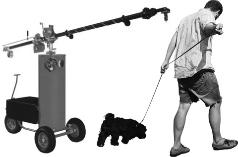
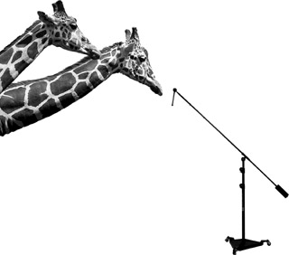
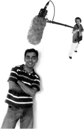
Sometimes, longer, more directional mics are attached to a boom that is moved around by a boom operator. This is common for dramas and sitcoms where actors move about but where seeing the mic would spoil suspended reality. Booms come in various sizes and with varying degrees of maneuverability. Large perambulator booms are motorized and can move the mic into a variety of positions: up, down, left, right, in, out. (See Figure 7.13a.) Usually, it takes two people to operate a perambulator: one to drive it and one to position the mic. Smaller booms, called giraffes, have wheels and can be operated by one person. (See Figure 7.13b.) Simpler yet is the fishpole, a pole with a mic on the end that a person holds and moves above the heads of the people who are speaking. (See Figure 7.14a.) Similar to a fishpole is a shotgun, a device that has a barrel to hold the mic and a handle, similar to a gun, which allows the operator to point the mic at the talent rather than hold it overhead. (See Figure 7.14b.)
The perambulator boom has the obvious economic disadvantage of requiring two people to operate it—who both must be paid. Both it and the giraffe use up valuable floor space, though more and more large studio productions have taken to putting the boom up on a catwalk above the studio floor. A fishpole is smaller but is difficult to hold for a long period of time. A shotgun is also smaller and can be held more comfortably. All four types of mounts, which are generically often just called “booms” for simplicity, can cast unwanted shadows; but, on the positive side, they are flexible and free the talent from wearing or handling microphones.
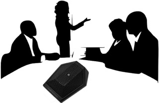
Sometimes, mics can be mounted on set walls or furniture. The boundary mic, also called a pressure zone mic (PZM) or surface mic, is effective for this use. (See Figure 7.15.) Its flat shape enables it to pick up overall sounds, so it is often used to gather audience laughter or applause. It is also effective for talk shows where participants sit around a table.
Mics can also be hung from the ceiling grid. While this mounting frees up a boom operator, it limits the actors’ movement: If they walk away from a hanging microphone, their voices fade “off mic.” Sometimes, especially for sitcoms, a mic is hung right above a door where people often stand and deliver a line as they leave. Mics can also be hidden in props on the set, but, once again, they can be used only when actors are standing relatively close by.
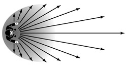
If a mic must be at some distance from the talent (more likely out in the field than in a studio), a shotgun is the mic of choice because it can be positioned on the ground or on a stand. A very long mic is selected with a super-, ultra-, or hypercardioid pickup pattern. The mic might also be mounted in a sound-reflecting dish, or umbrella, which reflects less directional sound waves into the mic, enhancing the sound beyond the directional sound waves only. This type of mic is often seen on the sidelines of field sporting events, such as football and soccer.
A sportscaster on a remote production often wears a microphone that is part of his or her headset. Referees on the field might wear wireless mics to announce their calls. When it comes to gathering and recording sound in remote situations, audio engineers can get creative, affixing mics to skiers’ helmets, race car dashboards, or tree branches where horse riders stop in the shade.
Outboard Equipment
In studio production, the output of the microphones usually goes to the audio board to be amplified and mixed. It is usually balanced with sound from outboard equipment (hardware that is outside the board). Outboard equipment plays back material that has been prerecorded on some medium, such as a computer, CD, or MP3 device.
Some equipment that records audio output is for audio only, such as an audio-only software program or a digital audio recorder. Other equipment records both video and audio, such as a video software program or a digital video recorder. Much of this equipment is discussed in Chapter 10, so here we concentrate on equipment that is audio only, most of which is used to play back rather than record.
Video recorders and servers also play back program material, such as news packages or opening and closing credit montages. Some productions, especially news, are likely to have both audio and video playing back from satellite and microwave feeds. But for many sound elements of TV programs, the playback comes primarily from digital or maybe older analog audio outboard equipment. You may be familiar with some of this equipment, having used it in your home. Professional equipment operates much like consumer equipment but often has more precise controls for engineers to tweak things more exactly, and it is sturdier because it is used for many hours of the day.
Professional equipment usually also provides superior sound in terms of frequency response and signal-to-noise ratio (SNR). Frequency response was discussed previously regarding microphones. High-quality outboard equipment is capable of receiving a wide range of frequencies, from very low bass sounds to high trebles. The signal-to-noise ratio measures the amount of wanted sound that gets through a piece of equipment in relation to the unwanted noise that is not part of the original sound signal. Usually, this unwanted sound comes from mechanical gears or electronic circuits. The higher the SNR, the better. Professional analog equipment usually has at least 60 units of signal for each unit of noise, and digital equipment has an SNR as high as 80. In contrast, consumer equipment might have an SNR closer to 40 to 1.
Digital Equipment
Microphones need to start out as analog because noises (such as the human voice, a clarinet, a falling chair) are analog—they send out waves of sounds, not 0s and 1s. But once sound is transduced into electrical energy, it can be converted to digital. (Refer back to Figure 1.8.) This transformation takes place within an analog-to-digital (A/D) converter that can be freestanding or can be part of a microphone or some other piece of equipment, such as a recorder or audio board. Most digital outboard equipment has provisions for converting from analog to digital and vice versa.
The concepts of sampling and bit rates are important for digital recording and playback. The sampling rate is how many times per second analog information is converted to the 0s and 1s of digital technology. The most common rates are 44.1 kHz (44,100 times per second) and 48 kHz—the higher the sampling rate, the better the quality. These high sampling rates were developed using the Nyquist sampling theorem (named after one of its discoverers), which states that an analog wave can be perfectly reconstructed if the sampling rate exceeds two times the highest frequency. Because the highest frequency that humans can hear is about 20,000 Hz, a sampling rate that just exceeds 40,000 times per second offers full fidelity—hence, the 44.1 kHz rate (developed for CDs) and the 48 kHz rate (developed later for digital recording, in part because it is mathematically easier to divide for compression). Beyond these rates is the point of diminishing returns because human ears cannot perceive any difference in quality at higher rates.
The bit rate is the number of 0s and 1s used to represent each sample point. Professional audio uses 16-bit sampling, meaning that a string of 16 0s and 1s is used for each sample. While professional-quality sound uses relatively high rates, such as 48 kHz at 16 bits, this takes up more storage space than audio sampled at a lower rate, such as 22 kHz at 8 bits.
Servers, Hard Drives, and External Drives
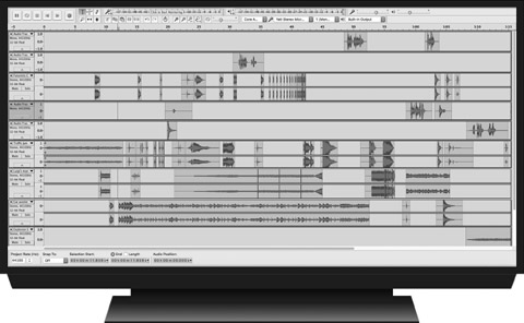
Most studios utilize a computer server or hard drive for playing back both audio and video files. If a computer is used only for audio, it is sometimes referred to as a digital audio workstation (DAW). A DAW can be used for editing and altering sound elements: basically anything that is completed prior to production using audio editing software that works similar to the editing software described in Chapter 11. (See Figure 7.16.) Once the editing is completed, the sound can be played back from the DAW through the audio board or some other piece of equipment. For playback, the sound can be played from the editing software or any media program (e.g., QuickTime, Windows Media Player, VLC, Audacity, Audition, ProTools). Computer drives can also store entire sound libraries, such as copyright-cleared and royalty-free music and sound effects. In addition to built-in computer hard drives, portable external drives and flash drives can also store and play back audio (and video) elements.
MP3 Devices
Any device that can play (and record) MP3 audio files, such as an iPod, can be connected to an audio console for mixing and playing in the final output. These portable devices are particularly useful for their simplicity in downloading sounds (and images) from the Internet. Of course, the user must understand that most audio and visual content is copyrighted and the appropriate permissions must be obtained if the elements are not in the public domain or if the fair use standard of copyright law is not met (1976 Copyright Act, Title 17, Ch. 1, Par. 107).
CD Players
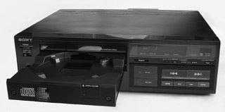
A very useful piece of outboard audio hardware is the good old CD (compact disc) player. Many audio setups have two CD players so the audio operator can undertake transitions from the sound on one to the sound on the other (e.g., segue, cross-fade). Professional CD decks cue up quickly so there is no dead air when playing back or making transitions. (See Figure 7.17.)
Although MP3 players are more popular than CD players in some situations, many audio libraries (prerecorded music and sound effects) can still be purchased in CD sets. Also, if you purchase a music or sound library that you download to a server or computer, you might consider backing up the files by easily burning them onto a CD set. That way, you’ll have the physical disks if the server or computer should ever crash. The quality of the digital sound (CDs have a sampling rate of 44.1 kHz at 16 bits) and the small size and sturdiness of CDs also make this an excellent technology for production. CDs are not indestructible, however. You must be careful not to scratch them or get fingerprints on them, because the laser within the CD player might not be able to read the data.
DAR and DAT
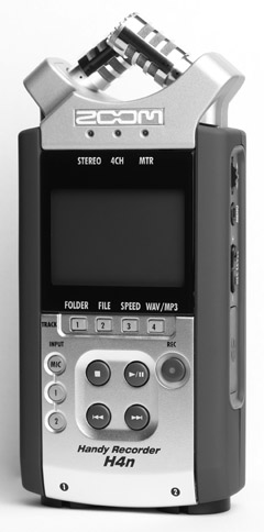
Digital audio recorders (DARs) can also be connected to the audio system in a control room for playback. DARs vary from small, handheld units to larger units. They usually have built-in mics to record audio as stand-alone units, and they also have professional mic inputs for connecting microphones for professional recording. DARs record sounds directly to solid state media such as internal drives or SD cards. (See Figure 7.18.)
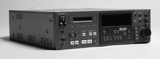
Still popular among professional sound engineers because of its high quality and durability is digital audio tape (DAT). With DAT, digital information is recorded onto a tape at either 44.1 or 48 kHz. A small 1/8 inch cassette tape can hold several hours of material. Portable units can record in the field, and larger console units can play back the material for studio production. (See Figure 7.19.) Generally, both DARs and DATs are used for material specially recorded for a particular program (e.g., comedy and drama) as opposed to preproduced material (e.g., music and sound effects). DARs and DATs cue easily and accurately and have visual displays that help navigate through the sound files, whether they are on solid state or tape media.
Analog Equipment
When TV production facilities buy new audio equipment, they invariably buy digital. But analog audio equipment from the past is still used. Digital sources can go down, and certain media are only available in analog form. Some facilities still have at least one turntable for playing vinyl records, which comes in handy for older music that has not been re-released on CD. Cueing a record is harder than cueing a CD. You must find the spot you want and back up half a turn so that the turntable has time to get up to speed when you want to use the sound. Analog cassette recorders are also still in use. They are very inexpensive and can be used to acquire material to include within a program. Analog cartridges (carts) were used for many decades but are now found rarely in production studios. They had a continuous loop of tape with an inaudible signal to cue the sound to the beginning. They were replaced by digital carts, which stored sounds on built-in microchips and could be cued with the ease of analog carts; however, digital carts have pretty much been replaced by high-capacity servers that store thousands or millions of sound elements (e.g., songs, sound effects) that are programmed via simple computer software.
Cables and Connectors
Cables and connectors are wires and metal joints used for channeling—moving sound from one place to another. Sound can also move through the airwaves wirelessly. The sound from someone’s lips is “channeled” to the microphone through the air. As already mentioned, wireless mics send the signal from a small antenna to a nearby receiver. Signals from the television station antenna travel through airwaves, as do signals from a satellite or microwave transmitter.
Within a studio, where distances are short and most equipment stays in the same place, channeling is generally done through cables. Both the cables and the equipment have connectors so that sound can be channeled a number of ways. For example, most microphones have a connector at the end so that the mic can be connected to a cable with a similar connector. This cable has a connector at the other end that can plug into the audio board or, if preferred, into some other piece of equipment, such as directly to a digital or analog recorder.
In reality, cables rarely go directly from microphones in the studio to the audio board in the control room because the studio floor would be cluttered with wires. More often the mic cables plug into connectors placed in the studio walls, with those connectors positioned near where the talent speaks. Sometimes, mics plug into a snake, which is a box of multiple connectors that can be moved about the studio. A snake has a single, thick cable that contains smaller wires for each connector, and this cable goes to the wall. Inside the wall, wires lead to the audio console where, once again, connectors channel the signals into the board. Additionally, wires from the pieces of outboard equipment (computer, CD, etc.) are channeled into the board with cables and connectors. From the board, more connectors and cables channel the sound out to the recording devices.
Types of Cables
Most cables used for TV production consist of copper wires encased in plastic sheathing. Sometimes, fiber optics (thin strands made of glass) are used in production, but they are more likely to be utilized for distribution of signals, particularly in cable TV and telephone systems.
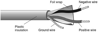
Cables that hold copper wires can be either balanced or unbalanced. Balanced cables have three wires—two to carry the signal and one to act as a ground. (See Figure 7.20.) Unbalanced cables have just two wires—one carries signal, and the other carries part of the signal and also acts as a ground. Balanced cables are higher quality (and more expensive) than unbalanced cables; they are less susceptible to the electronic interference all around us, such as a vacuum cleaner or power tool. Generally, professional studios use balanced systems, while unbalanced cables are found in consumer gear.
Types of Connectors
A variety of connectors are used for studio, field, and remote production. (See Figure 7.21.) One commonly found in the studio is the XLR connector. It has three conductors and so is compatible with the three wires of balanced cables. With the aid of a guide pin, the prongs of the male plug fit into the female jack so that they are tightly connected. The only way to unlock them is to press on the connector lock.
Digital audio often uses a BNC connector, which was previously used for video and is of high quality. USB connectors are useful for audio (and video) because they can pass a high-quality signal and are ubiquitous; for example, microphones that are made to plug directly into computers and gaming consoles have USB connectors, as do external drives that store audio (and other) media files. Another type of connector is the phone connector. The sleeve and tip of the male plug fit into the female jack. A miniphone connector is similar to a phone connector, except it is smaller and, therefore, popular for much consumer equipment (e.g., headphones, earbuds). Male RCA connectors have a prong surrounded by an outer sleeve that fits into the female jack.
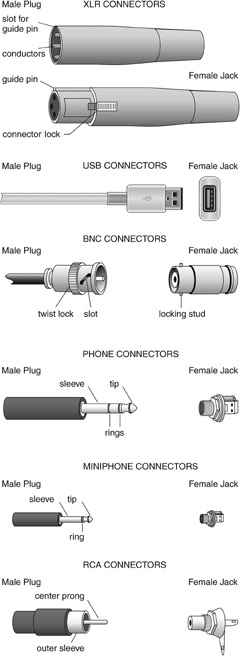
There are a variety of connectors because each has a different purpose. As already noted, XLR connectors are used in professional situations because they are part of a balanced system. However, they are large and bulky, so they are not suitable for most consumer gear, which is more likely to employ miniphone connectors. RCA connectors are versatile in that they are used for both professional and consumer applications and also for both audio and video. Both phone and miniphone connectors can carry either mono or stereo sound. If the connector has one ring, it can carry only mono; if it has two rings, it is capable of transporting stereo. For the XLR, BNC, and RCA connectors, one connector can carry only mono. Two connectors are needed to handle stereo, one for the right channel and one for the left.
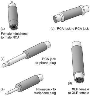
Sometimes, two pieces of equipment that need to be connected have different connectors. For example, a CD player with an RCA connector might need to connect to an audio console with an XLR connector. Other times, the equipment might have a male plug, but the end of the cable also has a male plug and the two cannot connect. To solve these types of problems, there are adapters. For example, the female end of an adapter is a miniphone, and the male end is an RCA, or both ends of an adapter are female RCA. Figure 7.22 shows an array of adapters.
Patch Bays and Routers
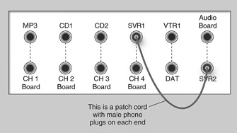
Sometimes, the wires from mics and outboard equipment go to a patch bay or a router, and from there to a variety of places, such as different inputs on the audio board, an audio recorder, a video recorder, and the station transmitter. Patch bays are boxes that consist of a large number of phone jacks. (See Figure 7.23.) One row of jacks is for sounds coming from equipment, and another row is for sounds going to equipment. Each piece of equipment is wired to the back of a particular jack.
When a signal needs to go from one place to another, you simply use a cable (usually called a patch cord), either with male phone plugs or with some other type of plugs at each end to transfer the audio from the top row to the bottom row. Figure 7.23 shows a patch bay with a patch cord going from Server 1 (SVR1) to SVR2. If you do not put in a patch cord, the sound goes from whatever is on the top row to whatever is on the bottom row because that connection is normalled—the “normal” or default connection without patching. Using Figure 7.23 as an example, if SVR1 is not patched into something else (such as SVR2), its sound goes to channel 4 of the audio board—the place it normally goes.
Patch bays are from the analog world, whereas routers are more likely to be found in digital facilities. Routers are “black boxes” with internal circuits that do all the channeling, rather than having external patching modules. They channel sounds to various places by moving packets of digital 0s and 1s, often within a network configuration. Sometimes, audio boards also serve as routers, and, sometimes, computer software allows properly connected audio signals from any source to be sent to any other source with the click of a mouse.
Care of Cables and Connectors
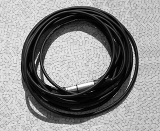
Cables and connectors must be handled very carefully because they can be easily damaged. In fact, they are the parts of the audio system that are most likely to give you trouble. The tiny wires of cables can be easily broken, and these broken wires are particularly difficult to find because they are inside the plastic casing. To prevent this breakage, cables should be neatly coiled after they are used. One effective coiling technique is to string the cable on the floor in a figure-eight pattern and then fold the two halves together. Another technique is the over-under method, in which one coil is made with the long side coming off the top of (over) the coil, and the next coil is made with the long side coming from beneath (under) the coil, repeating the pattern until the cable is coiled with no kinks. When cable is coiled properly, it should look like the cable in Figure 7.24. Note that there are no kinks or twists and that the loops have a consistent diameter (about a foot in the case of this XLR cable). It takes discipline to do this neatly and correctly at the end of a grueling production, but it pays off in the long run with less damage, longer-lasting cables, easier and more compact storage, and no messy cable spaghetti the next time someone needs to retrieve a cable.
You should never pull on a cable when you disconnect it. Pull on the connector instead. However, you must also treat the connector gently. Don’t force it, because the prongs can bend or break, rendering it ineffective.
Audio Consoles
It seems obvious now that the ability to blend and select a number of sound sources and to control separately the volume levels of each is a primary requisite for any type of audio production. History tells us, however, that early radio studios had only one microphone and that volume control was accomplished by placing people and musicians closer to or farther away from one mic. Fortunately, engineers developed the audio console (also called the audio board), which allows a number of audio sources to be fed into and processed by this one piece of equipment.
Types of Consoles
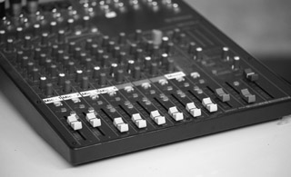
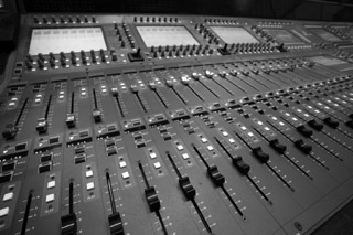
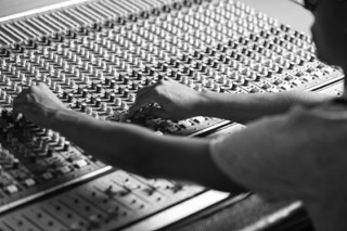
Audio consoles come in many configurations, from very basic to very complex. Basic ones are usually used for live and live-recorded work. (See Figure 7.25.) More-complex ones are used for postproduction editing and complicated production, such as recording musical bands. (See Figure 7.26.) TV stations usually try for something in the middle. (See Figure 7.27.) Basic consoles often do not have enough knobs and buttons to fulfill all the needs of a TV facility. But complex, expensive boards with extensive capabilities can have too many features. When you are working in a TV facility, you rarely have time to change these settings. In fact, a large number of controls can impede you because something is invariably set in the wrong position for what you want, and you have to troubleshoot through an array of controls to correct the problem. However, some facilities cannot afford multiple boards, so they opt for a more complicated board that can be used for a variety of applications.
Another difference among audio consoles is that some are analog (refer to Figure 7.25) and some are digital (refer to Figure 7.26). Digital boards—developed after analog boards—have been designed to minimize the learning curve for someone who has operated an analog board and needs to learn a digital board. As with other equipment, when TV facilities need new audio boards, they usually opt for digital. Digital boards are naturally more computer-based than analog boards, and, although most of them have actual levers, buttons, and knobs similar to analog boards, they also have LCD computer screens where functions can be changed with the click of a mouse or some other control. For this reason, digital boards can take up less space than analog boards. Analog boards need to have buttons and knobs for many functions just in case they are needed. With digital boards, functions that are likely to be used less often or that can be set ahead of time are relegated to the computer and brought up only when needed. Some analog boards have digital elements to them. For example, you can save settings for an analog board in a computer and then recall them for a program a week or two later. Digital boards allow you to do all this internally.
In addition, some boards are mono and some are stereo, with stereo being more common. Some stereo boards duplicate everything for the left and right channels. Others have separate stereo controls so that the left and right channels can carry discrete sounds, while keeping those sounds synchronized for the final output.
The Basic Console
To explain how a board works, we have designed a generic board that illustrates common board features. (See Figure 7.28.) Refer to it frequently as we discuss the various functions of the board. For simplicity, we have designed this console to look like a basic monaural board. However, the functions it performs are the same as those for more-complex and stereo boards, and we will discuss features that are beyond the basic ones depicted here.
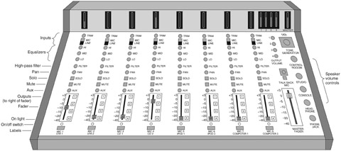
In all probability, this discussion will include a number of features your board does not have, and it will also not mention some that your board does have. Also, controls will be in different positions on our mock board than on yours. The only way to understand fully the operation of an audio console is to work with it. When you have mastered one board, it is easy to transfer your skills to another board, because they all operate on the same principles.
Our generic console is called an “8 in, 4 out” board. It has the capacity to manipulate eight different sounds at the same time. (You can actually wire in 16 sounds, two per input that you select with a mic/line switch to be discussed shortly, but you can’t play them all at the same time.) Whatever you bring into the board can be sent to four different places as it leaves the board. Even this basic board might look a bit intimidating to you because of all its knobs and buttons. But if you look at it carefully, you can see a great deal of duplication. Each input channel has the same controls up and down each column, and they all work the same way.
Board Functions
Generally, an audio console enables its operator to bring a number of different sounds into the board, alter their characteristics if desired, mix them together, adjust their relative levels (balance), and then send them on to their next destination. To explain how the board works, we will look at the most basic functions: powering, inputting, shaping, mixing, isolating, outputting, and monitoring.
Powering
The very first thing you do with an audio console is turn it on. Most boards have a master power switch that is often in an inconspicuous place, such as the back of the board (that’s where the one on our generic board is hiding), so that someone does not accidentally turn it off while operating other controls. Often, there are on/off switches for each channel, too, such as those at the bottom of Figure 7.28. If you are not using a channel, it is best not to have it turned on because some sound might accidentally come through. Some boards have two large buttons, one for on and one for off. We have designed our board with one button that toggles on and off. A small red light above the button lights up when the channel is on.
Another aspect of power is that some boards have a switch that can send phantom power to condenser mics, as mentioned previously. We don’t have that switch on our generic board, but phantom power provides a good example of why a digital board can be smaller than an analog board. An analog board would need a phantom power switch for each channel, just in case that channel were used for a condenser mic. A digital board would not need only one switch. Phantom power could be selected on the computer screen for the particular channel that needed it. Once the power is activated, it does not need to be changed during the production.
Inputting
As mentioned previously, our console has eight input channels, enough to illustrate board principles. Most boards have more—inputs from telephones, satellite feeds, field locations, and so forth. You will note that all the inputs can be used for microphones or for some piece of outboard equipment (a situation to be explained shortly). We have labeled the channels; it is a good idea to label the board to whatever extent possible. We have arranged our board with the idea that we will generally use the first two or three positions for microphones and the rest for outboard equipment that we use frequently. We are assuming we don’t use our VTRs much anymore, and for some programs we can make do with one CD player, but we use the iPods and computers frequently.
At the top of the board you see a switch for indicating whether the sound on the channel will be a mic or outboard (line) equipment—that is, whether each channel is a mic feed or a line feed. This selection is necessary because a mic input requires more amplification. The sound that comes from a microphone is very weak and needs to be amplified a number of times as it is channeled through the system. Audio boards have amplifiers built into them that boost the microphone signal. Line sounds, in contrast, are already recorded and amplified at the time they were acquired. They are now line-level audio, and, while they might need to be amplified a little, they do not need as much amplification as the sound from a mic. Therefore, the board does not route line audio through an amplifier as it does mic audio.
Both mic and line equipment plug in on the back of the board, and you should make sure never to plug a mic into a line input or vice versa. Doing so makes the audio unusable and can damage equipment—and ears. Specifically, if a mic is connected to a line input, the sound is not amplified enough to be heard; and if a line (outboard) source is plugged into a mic input, this prerecorded sound is amplified again and is too loud and distorted. Not all outboard equipment (or mics) needs to be amplified the same amount, so a potentiometer or pot (sometimes referred to as trim) can be used to fine-tune the amplification.
The input channel cannot be used for a mic feed and a line feed at the same time. However, the operator can switch back and forth between the mic and line position during a production. If, for example, the production requires eight mics, then the audio operator should make sure the person on mic 8 does not speak right before an audio file is played from computer 2 so that there is time to change the mic/line switch on channel 8 to accommodate both mic 8 and computer 2.
To help with the operation of the inputs, some consoles have remote controls for outboard equipment. By using them, the operator can start or stop audio recorders, CD players, and other equipment without having to physically reach the other hardware. Equipment without remote controls must be located next to the audio board to give the operator easy access.
Shaping
Shaping, often referred to as signal processing, involves altering the tonal characteristics of sound, usually to eliminate flaws or create special effects. Often, the goal of an audio operator is to reproduce the same quality and dimension that existed in an original sound pressure wave, replicating the natural sound as we would hear it without electronic intervention. For example, when we see a close-up of an actor talking on screen, we expect to hear that actor’s dialogue crisply and cleanly, as if he is standing next to us in the room. A related goal is that of creating an enhanced version of that original sound so that it sounds like the tone the listener expects to hear in a program. For example, when we see a person fire a gun, we expect the sound to be loud and resonant, even if the actual gunshot is a quiet pop. The problem of turning natural sound into electronically reproduced sound is that much of what shapes the quality of the sound is affected by the equipment used and the physical conditions of the recording location. For example, if the microphone does not produce overtones well, or if the recorder has a low signal-to-noise ratio, the audio will not sound like it originally did.
Sometimes, sound needs to be changed to fit the creative needs of a program. For example, you might want to make a voice sound like it is coming from a phone, which involves filtering out overtones to make the voice more hollow or tinny. If a scene takes place in a cave, you need to add echo so the voices sounds like they’re in a cavern. These are all situations that can be helped by signal processing.
We have placed just a few samples of shaping capabilities on our audio console. These controls are more prevalent on boards used for postproduction, because when you are altering sounds it takes experimentation to get it right. Fast-paced studio productions don’t usually leave much time for experimentation. Also, the studio is a controlled environment so sound can be recorded with very few, if any, flaws.
However, we have included a bit of equalization7 on our board to enable us to alter the frequencies of sound. The equalizer unit in this board handles high, middle, and low frequencies separately so that we can emphasize or de-emphasize ranges. For example, if we want to give someone’s voice a deeper sound, we might turn the knob for low frequencies so they are maximized, leave the knob for mid-frequencies in the center position, and adjust the high-frequency knob slightly to lessen these frequencies.
We have also included a high-pass filter. Filters deal with frequencies also, either cutting out a certain band of frequencies or allowing a certain band to pass through. A high-pass filter allows high frequencies to pass through, so it is good for blocking low-frequency rumbles that are sometimes picked up from power lines.
Another control on our board is a pan knob. It controls the amount of each channel that goes to the left and right speakers. The center, or 12 o’clock position, sends the signal equally to left and right. Some boards are able to control for surround sound, but, because that is quite complex, it is better suited to digital boards that can handle small gradations of control.
Boards can also include signal processing that deals with amplitude. For example, they have compressors that reduce dynamic range by compressing, or narrowing, the distance between the lowest and highest volume levels, in effect raising the lowest levels to bring them up close to the loudest levels the system can handle. Note that this type of compression (narrowing amplitude) is different from digital file compression—reducing file size by removing redundant 0s and 1s. Some audio consoles also have limiters that do not allow the signal to go beyond a certain volume, in essence putting an electronic cap on the level.
Signal processing covers time control as well. For example, digital delay holds what a person is saying for several seconds before it is sent to the transmitter. This is so the sound can be stopped if the person says something not fit for air. Its most useful application is during live shows. Reverberation gives sound a bit of a bounce or echo by repeating the sound at a lower, more distant level a fraction of a second or a full second or more later (the time delay and amount of echo, or reverb, is set by the control knob). This might be useful, for example, if you want audio that was recorded in a studio to sound like it was recorded in a cathedral. Some digital boards have a library of sound environments, such as a large auditorium or a closet, and the appropriate signal processing parameters are preset to produce those environments. Although these shaping processes (and many more) can be incorporated within audio boards, they can also be performed by a variety of outboard hardware and software.
Mixing
A major purpose of an audio console is to mix sounds together—voice and music, two sound effects, four people talking. This is accomplished through fader bars, or simply faders (positioned near the bottom of the board) that control the volume level (sometimes referred to as the gain) of the sound for each particular channel. The 0 dB position on a decibel scale8 (also 100-percent position on a percent scale) is usually the optimum area for analog sound; however, the reason to have faders is to vary the gain. If someone with a loud voice is speaking into mic 1, you would set the volume lower than you would for talent with a soft voice on mic 2. Some boards do not have faders that move up and down; rather, they have knobs that turn right and left to increase and decrease the gain, respectively. These knobs, mentioned earlier, are referred to as pots (short for potentiometers).
When you operate a board during production, you often need to bring a particular fader up to fade in a sound and take it down to fade out a sound. Or you may do a crossfade, where you bring one sound in slowly while you take another out slowly, momentarily blending the two sounds for the number of desired seconds. Using our sample board again, if you are doing a crossfade from music on CD player 1 to music on CD player 2, you would gradually bring channel 3’s fader down while raising channel 4’s fader. The other main type of audio transition is called a segue. This is a more abrupt change from one sound to another, in which the first sound is faded out, followed by the second sound being faded in. There is no blending of the two sounds. For effect’s sake, you might want to move abruptly from the middle of a piece of music to a voice statement coming from computer 1. You would lower channel 4’s fader quickly and then quickly raise channel 7’s fader.
As previously mentioned, some consoles allow you to set levels for a particular program and then memorize them within the board software. You can do this during rehearsal for a complicated program and then use the settings during actual recording. You can also set them for a recurring program that has a regular audio pattern. Sometimes, these settings are combined with motorized faders that allow for very smooth transitions.
Isolating
Sometimes, you do not want to hear all the sounds coming from the board. You may want to hear one particular sound alone; perhaps you want to equalize it or cue it up for playback. Pushing the solo button on a given channel allows you to hear just that channel’s sound and not the other sounds. The mute button works the opposite way. When you select mute, you do not hear the sound from that channel, but you continue to hear all other sounds from the other channels.
It is possible to mute or solo several channels at once, and on some boards it is possible to group solo or mute buttons so they all go on or off at once. For example, you might want to group all the talent mics so you can mute them quickly whenever there is a commercial break. Our board just has simple solo and mute buttons for each channel, so if we wanted to mute several channels at once, we would have to push all the relevant buttons.
Some boards, usually those that do not have the solo function, have a cue button, also called audition. This is used to get something ready that you don’t want to record. For example, before production begins, you can listen to the iPod so you can pause it at the point where you want it to start and then bring it in later in the program.
Outputting
If you look next to the faders, you will see four buttons numbered 1 through 4.9 These are the “4 out” function of our “8 in, 4 out” audio console. These buttons determine where the sound goes when it leaves the board—up to four different destinations. The destinations are whatever devices the engineer wires to the four board output channels.
In a TV studio, you want one of the outputs to go to the DVR or computer or server so the sound can be recorded with the picture. You might want another output to go into the studio for when talent needs to hear the program audio (e.g., dancers). Perhaps you want to send one output to a computer that is set up for an audio-only recording of the program. You might simultaneously send the sound to a studio transmitter. The signal can go to all four places at the same time; you simply push the buttons for the designations you want. Each channel has its own selection of outputs because you might want to send only part of the sound to a particular place. For example, if you are making a CD, you might want to record only the voices coming through the mics, and not the music from an iPod.
The master fader at the right end of the board controls the sound for the whole board. If it is down, nothing passes through the console. If something unusual happens and you want to lose all sound, a quick way is to take down the master fader. At the same time, and far more likely, if you are not getting any sound out of the console, chances are you have not raised the master fader (or faders if the board is stereo or surround). At the start of each production, the master fader should be up to its normal, zeroed level.
A more complicated concept is that of submastering. If you have many sources coming into a large console (perhaps a 24-in board), you might want to group some of them together so you can raise one fader to activate all of them. For example, if you have four mics over the violin section of an orchestra, you probably want to activate all of them at once. You can use a group assign switch to assign the four channels for the violin mics to one submaster fader. Likewise, you can assign the microphones covering the percussion section to another submaster. These submaster faders are used to mix groups of sounds.
Many boards have an auxiliary send feature, or aux, such as that located above the input faders on our board. This, too, is a type of output. Using the aux send feature, you can send the sound to external equipment, such as a stand-alone compressor, which can alter the sound and then send it back into the board. Aux can also be used to send the program audio to another source, such as the boom operator’s headphone or the talent’s IFB.
Some consoles include a mix-minus module. This sends the program mix, minus the audio being recorded, to a destination. One common use for mix-minus is for vocalists. All the instrumental music is sent to the singer’s earphone, and he or she sings and records the vocal track without the vocals being sent back to the earphone. Mix-minus is also used when reporters located at some distance from each other are all reporting on the same story and need to hear what everyone else is saying without the annoyance of hearing their own voices, which would likely return to them with a delay or echo and possibly some feedback.
Monitoring
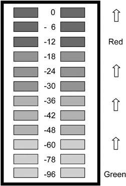
Obviously, you want to know that sound is getting from the inputs to the outputs of the console in an acceptable manner. The volume unit (VU) meter provides a visual description of volume levels and the degrees of difference among the ongoing level changes. Some VU meters, such as the one in Figure 7.29, have a needle-sized pointer that is in constant motion as it indicates differing intensities of volume. On other equipment, including our sample board, the meter consists of a column of LEDs. The effect is a bar of light that grows and shrinks to indicate ongoing changes in volume level (see Figure 7.30).
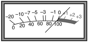
For VU meters that have a needle, this needle should peak (reach the high point of its swing) at the “0” position (refer to Figure 7.29). For LED meters, the color of the lights usually changes from green to red at the point where the signal should peak (usually either -12 or -20, depending on what value the manufacturer uses to calibrate sound). It is very important that the audio operator pay attention to the peaking point because, as the amplification of the signal increases beyond this point, not all frequencies are equally amplified. With analog sound this results in distortion. Digital sound that is too loud for the equipment often clips, recording only a clicking sound at that instant. For this reason, it is advisable to keep digital sound slightly below the zero point. Some boards are equipped with a peak program meter (PPM), which measures loudness peaks. A PPM reacts more quickly to overmodulation than a VU meter and can help keep sound from distorting (analog) or clipping (digital). Whether analog or digital, in addition to problems with the gain being too high, if the gain is too low, dropping below an acceptable minimum, the sound is not processed by the system and is lost.
We have equipped our board with a meter for each input channel, a meter for each of the four output channels, and a meter for the master fader. The regular procedure for our generic board is that the master volume would be set at 0. If the board is properly engineered, when the tone generator is turned on, the tone level should register right before the lights change from green to red.
The tone generator, located in the upper right of our board, is used to calibrate sound levels throughout the system. It creates a steady tone at 1 kilohertz. If the master fader is at 0 and the tone generator is turned on, then the volume controls for the four outputs (the pots above the master fader) can all be set so that these outputs are at the same level—the last green LED. By setting the tone in this way, sound levels are consistent as they move from one place to another. For example, when the tone on output 1 has been set, then that tone can be sent to the recording device (computer, DVR) so that the recorder’s VU meter can be set to the same normal level. Then the sound coming from the audio board will be the same volume as it goes into the machine and is recorded. Once you have calibrated all the equipment, you should not move the master fader or the output pots or the levels on the record machine, because doing so upsets the consistency of audio levels from one place to another.
Meters give you a visual representation of the sound, but they do not let you actually hear it. To hear sound created within the board, you need amplification and speakers. Speakers are generally stand-alone boxes located in the studio or control room (more on this in the next section). There might also be a tiny speaker in the console itself that can be used for cueing material. It is also usually possible to hear the sound through headphones plugged into the board. Being able to use the console speaker or headphones is particularly helpful before production begins, when people in the control room want to communicate with each other and concentrate on their jobs without the annoying noise of the same music clip being played over and over. If a board has a talkback mic (located above the master fader on our board), the audio operator can use it to talk through the studio speaker and communicate with crew and talent about mic levels. Because the person’s voice is heard in the studio while the person is still in the control room, some joke that the voice sounds like it is booming down from the heavens, giving a talkback mic the nickname “god mic.”
The volume controls for all the speakers—control room, studio, console, headphones—are on the console (refer to far right on Figure 7.28). These volume levels are not set with the tone generator and are not tied to any meters. The levels in the speakers and headphones are independent and do not affect the recording level.
This brings up the important difference between loudness and gain. Loudness is how loud you hear a sound through a speaker or headphone. Gain is the actual level of the audio being processed and recorded. A great many students and beginning board operators have been tricked by turning the control room monitor up loud while having the program levels low. They think they are recording good sound because they can hear it clearly, but in reality the sound they are recording is too low. The best way to prevent this problem is to calibrate all the meters and set the speaker and headphone levels correctly before recording begins.
Additionally, always watch the VU meters during production to make sure the levels remain in the safe range; that is, develop the discipline of watching your audio gain in addition to listening to your audio volume. Don’t set the levels at the start and then sit back and watch the show, assuming the levels are all right. Watch the meters and adjust the faders continuously as needed. This technique of monitoring audio levels constantly throughout a production is called “riding the gain,” and it is crucial for recording acceptable sound.
Speakers
A speaker, like a microphone, is a transducer, except that instead of turning sound energy into electrical energy, it turns an electrical signal into audible sound. Studio facilities usually have a number of speakers. There might be a speaker in the studio, and there is always at least one speaker in the control room, called a program monitor. It provides a high-quality reproduction of the sound coming from the audio board and going to a recorder or out over the air. In addition, there might be another speaker, called an air monitor, through which you can hear the sound as it is broadcast over the air for a live feed. Individual pieces of equipment often have their own speakers and earphone jacks so that the operators can hear what they are playing.
If the sound you are creating is stereo, there are two speakers—one for the right channel and one for the left. Make sure the speakers are positioned so that they give you an accurate sound reproduction. The general rule for speaker placement is that the distance between the speakers should be the same as the distance from the speakers to the listener.
Recording Quality Sound
Because sound conveys so much of the information provided by a TV program, it must be understandable and appropriate. Recording quality sound is not easy. You cannot simply place a microphone near the sound source and hope for the best. You must have the discipline to plan how the sound will be recorded and then follow through on that plan.
Choose the Right Mic
To record good sound, start by selecting the most appropriate microphone. How many people are you miking? If just one, you will probably want a cardioid. Is there any chance the mic might be handled roughly? If so, use a dynamic mic. Mics are very individual, so even though two microphones have the same specifications, one brand might work better for a particular performer than another. For example, a particular mic might cause sibilance (hissing “s”) and plosives (popping “p”) for Talent A, while Talent B sounds fine with the same mic. If this happens, try a different mic for Talent A or put a pop filter over the front of the mic. This is a ball-shaped accessory made out of screen mesh or foam; the mic shown in Figure 7.11 has a pop filter on it. In addition, many cardioid mics are subject to a proximity effect. As the sound gets close to the mic (about 2 or 3 inches away), the mic boosts the bass frequencies. Some men like this effect because it makes their voices sound deeper. Try to avoid having talent change microphones in the middle of a production. Because each mic has an individual sound, the talent’s voice quality changes when he or she starts using a new mic, destroying the aural continuity of the production.
Position It Properly: Know and Use the Inverse Square Law
Think through the method of positioning the mic. The best position is 6 to 12 inches from the person’s mouth, but that is not always possible. Often, compromises must be made, especially with mics on booms, because of shadow problems with the lighting or because of the height of the camera shot. If the camera has a wide shot and the mic should not show in the picture, keep the mic as low as possible and point it toward the mouth. Sometimes, you have to be creative with positioning. For example, if you use a fishpole and the camera has a long shot, you might try placing the mic near the talent’s feet and pointing it upward toward the mouth.
The distance that a mic is placed from the talent must take into account the inverse square law. This is the same principle discussed in Chapter 6 in relation to lighting. In terms of sound, it means that as the microphone-to-source distance is doubled, the loudness is reduced to one-fourth of its previous strength. Therefore, if you have an audio source (voice) giving you a constant level of sound at a distance of one foot from the microphone, and then you move the mic back to a distance of 2 feet, the strength of the sound pressure (loudness) reaching the microphone is only one-quarter of what it was when the mic was 1 foot from the source. If you are working with a relatively short source-to-mic position (e.g., a talk show), any distance change can be crucial. This is all the more reason to check the sound levels carefully before you start recording a program. Also, don’t be fooled by the sound you hear with your ears. You might hear people just fine when you stand 4 feet away, but the mic does not pick up the sound as well as you hear it.
Check and Recheck
To ensure good sound pickup, insist on checking the sound carefully during setup and rehearsal. Do a mic check by having the talent speak into the mic as they will speak during the program—not the usual “Testing 1, 2, 3” routine. If it is a talk show, have each person say a few things as they might say them for the show. If your talent is going to sit up straight and clearly enunciate “Testing 1, 2, 3” for the test and then slouch and mumble during the show, it is better to know this ahead of time than to try to compensate during the actual production. Have each person talk separately so you can set the optimum volume level for each ahead of time. You will still have to ride the gain during the program, but doing proper mic checks gives you good starting levels.
Provide Presence and Perspective
Your sound should have both presence and perspective. Sound has presence when it is loud and clear and sounds like it is coming from the person’s mouth. You do not want sound that is off-mic—that sounds as if it is coming from behind the person or off to the side. This is usually a matter of placing the mic near enough to the person’s mouth. (See Figure 7.31.) You also want to minimize the amount of sound you pick up that has bounced off a wall, creating an echo-type effect. (See Figure 7.32.)
Perspective is the relationship between the picture and the sound. The sound should be what the viewer expects. If a person is being shown in the distance in a long shot, the sound should be different than if the person is seen in a close-up. The best way to achieve proper perspective is to move the mic closer to or farther away from the person. The farther the mic is from the sound source, the farther the audience will perceive the sound source to be. For this reason, you should not use a lav mic if what you are recording calls for perspective changes, because a lav mic attached to a person always remains at the same distance.
Be Ready to Troubleshoot
Have the discipline to think ahead to problems that might occur. Are any of the performers going to move during the program? If so, make sure they have enough mic cable to move comfortably. You should have spare microphone batteries nearby. Some audio operators use dual redundancy: They mic the performer with two microphones, so that if one goes bad the other can quickly be put into operation. You usually don’t want to have both mics operating at the same time, however, because that can create a phase problem.
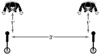
Phase problems arise when you place microphones too close together so that they pick up the same sound source. Their similar waveforms tend to cancel each other out when they get to the audio console. The result is disappearing sound or sound that goes in and out. To prevent this problem, you should obey the three-to-one rule, which states that if two singers (or other performers) are standing (or sitting) side by side, each working at a distance of 1 foot from their respective mics, then the two mics must be at least three feet apart. (See Figure 7.33.) If source-to-mic distance is increased, the mic separation must similarly be increased. A further application is that if a person wearing a lavaliere mic walks over to a boom mic, one of the mics must be turned down.
Adjust to Achieve the Right Balance
Anyone operating an audio board must pay careful attention to balance. This is the relationship of one sound to another, or the relative levels. The most common balance problem is that the music is too loud and drowns out the voice. This is fairly simple to fix by lowering the volume of the music. Harder to balance are the voice levels of different talent. If one person speaks very loudly and another is soft-spoken, the audio operator should attempt to balance their levels. Sometimes, this is simply a matter of having one fader higher than another, but often the position of the mics needs to be changed. If one mic is being used, it can be cheated toward the soft-spoken person; if two mics are being used, the soft-spoken person’s mic can be placed a little closer to the person’s mouth, taking into account the inverse square law.
Pay Close Attention
Recording good sound requires great discipline on the part of the audio operator, because it is very easy for sound to become unintelligible. That is why boom operators and audio console operators often wear headsets: They can concentrate on the quality of the sound they are recording and also listen for unwanted sounds, such as clothing rustle. Some sound operators close their eyes during rehearsal and recording so that they are not aware of the picture and can become totally absorbed in the sound. This demonstrates both discipline and technique in recording and creating quality sound for video production.
Focus Points
After reading this chapter, you should know . . .
- The role of frequency, amplitude, and pickup patterns as they relate to microphones.
- How microphones are constructed and where they should be positioned.
- Characteristics of digital outboard equipment, including servers, computer drives, MP3 devices, CD players, DARs, and DATs.
- Characteristics of analog recording equipment.
- The types of cables and connectors and their various uses.
- The role of a patch bay and router.
- How to care for cables and connectors.
- The types of audio consoles.
- Functions of typical audio consoles related to powering, inputting, shaping, mixing, isolating, outputting, and monitoring.
- Differences between mic and line feeds.
- The types of signal processing.
- The role of faders (including the master fader) and pots.
- Why audio boards have meters, and the functions of VU meters and PPMs.
- How speakers are used to monitor audio.
- How pop filters, the proximity effect, presence, perspective, the inverse square law, phase, and balance relate to effective audio production.
Review
- Name at least one piece of audio equipment in your facility that does each of the following: transducing, channeling, selecting, recording, monitoring.
- If you were the audio operator for a TV studio-based game show, what kind of mic would you use for the host? Cardioid or omnidirectional? Dynamic or condenser? Flat frequency response or with a speech bump? Lavaliere, handheld, stand, boom? Would you use balanced or unbalanced cable? What type of connectors would you use? Justify your answers.
- If the sound from the CD player is not getting through the audio board but the sound from the microphone is, what troubleshooting could you do to get the CD sound operating properly?
- Define the proximity effect, presence, perspective, and phase, and describe how you would handle these four aspects of sound properly.
On Set
- Prepare a list of the microphones in your school’s production facility. Look up the mics on the manufacturers’ home pages. Create a spreadsheet that includes the following information about each microphone:
- brand and model number
- construction (dynamic or condenser)
- pickup pattern (cardioid, omnidirectional)
- type (handheld, lav, shotgun, etc.)
- capabilities
- drawbacks
- typical production uses.
- Sketch your school’s studio audio console, outboard equipment, monitors, and other equipment related to audio. Identify the main components located within the console and other pieces of equipment according to whether they transduce, channel, select/alter, monitor, or record/play back.
- Record a television commercial. After watching it carefully, write a two-page analysis of the way in which audio is used in the production.
Notes
1Microphones have other characteristics that are important, such as impedance and sensitivity. Impedance reduces the amount of sound that gets through, and it is expressed in ohms. Low-impedance mics of 600 ohms or less are used in professional situations because they impede the sound very little. High-impedance mics (10,000 ohms and higher) are used for consumer equipment. Because they impede sound, they cannot have cables longer than about 6 feet. Sensitivity refers to a mic’s efficiency—its ability to create an output.
2Cycles per second (cps) was the first term used as the basic unit of measure for sound pressure waves and electromagnetic waves. The term cycles per second has been replaced with the term hertz (abbreviated Hz), in honor of Heinrich Hertz (1857–1894), who first demonstrated the existence of electromagnetic waves.
3Waves can also be discussed in terms of their wavelength. The distance between the peaks of two adjacent waves is the wavelength. Lower-frequency sounds, because they are more spread out, have longer wavelengths than higher-pitch sounds.
4A decibel is actually 1/10th of a larger unit, the Bel, named for Alexander Graham Bell of telephone fame. Two decibel scales are used in audio. One is decibel sound pressure loudness, or dBSPL. This scale measures the pressure of sound waves as they move through the air. It is the scale to which this chapter refers when noting that a whisper is about 20 dB and a gunshot is about 140 dB. The other scale is decibel milliwatts, or dBm. This scale is used in VU meters as a measure of the electrical strength of a sound: the amplitude of the electric waveform (dBm) that corresponds to the original sound volume (dBSPL).
5The simplest way to record stereo is to take the monaural signal from one microphone and send it to both the left and the right channels of the stereo equipment. This is not true stereo, however, and does not allow for effects, such as the sound of a train that moves across the screen.
6For information on how to mic for surround, a good place to start is the Wikipedia entry for “surround sound,” from which you can link to an explanation of a miking technique called a Decca Tree, often used for large orchestras, among other things.
7Equalization is either graphic or parametric. Graphic equalization divides the frequency response range into separate bands that can then be altered. The controls on the equalizer form a graph of the frequency bands so that some can be emphasized while others are de-emphasized. A parametric equalizer can control individual frequencies as well as a band of frequencies.
8Zero decibels (dBm scale, see note 4 above) has been calibrated to be a level that equipment can handle without distortion or clipping. Sound below 0 is marked with minuses, while sound above 0 is indicated with pluses. Some boards use percentages rather than decibels, with 100 percent being equal to 0 decibels. Digital boards are usually calibrated with either –12 or –20 as the normal level, rather than 0, and the value of 0 is then the highest possible range that the equipment can record without clipping.
9Most boards have more than four outputs, especially if they are used for stereo or the surround sound that is likely to accompany HDTV.