
The ability to record and play back video signals is crucial to nearly any video production. The majority of programming on network television is broadcast from a recording, and most of what isn’t relies at least in part on roll-ins, or recorded segments (see Chapter 12). Thus, we need ways of recording and playing back high-quality video signals (along with their associated audio signals). Additionally, an increasing amount of programming is now being viewed on desktop computers, smartphones, or tablet computers. Consequently, we need ways of recording, channeling, and playing back video signals that are compatible with these new modes of viewing.
As we know, since video exists increasingly in digital form, computers can be used to perform control, storage, and editing functions. You have already seen how digital technology has changed other video production components, such as cameras and switchers. In the same way, digitization has changed how video signals are recorded, edited, and played back, as digital media have almost completely replaced tape-based systems. For acquiring video, especially in the field, portable hard drives and solid state digital media such as memory cards are now the norm, while video servers are being used for longer-term storage and editing. The chief advantage of these new types of storage is that they are nonlinear, meaning you can access anything stored on them nearly instantly, without having to fast-forward or rewind as you formerly had to do with tape. And when video servers are combined with computer network interconnections, any number of people in a production facility can simultaneously access and manipulate the information.
The operation of video storage and distribution equipment involves important disciplines and techniques. The disciplines include an understanding of how video is recorded, stored, and distributed, while the techniques include specific operating and maintenance procedures. This chapter concludes with a discussion of special considerations regarding digital video designed to be viewed on portable devices or transported over the Internet. We begin, however, with a discussion of some technical aspects of video and their impact on how it is stored and distributed.
Video Basics
For the purposes of a discussion about channeling, monitoring, recording, and playback, we can divide video signals into three main types: analog NTSC, digital NTSC, and digital ATSC. Analog NTSC video signals are increasingly rare in production facilities, but they still exist, especially in university environments where the upgrade to digital equipment has not yet taken place. Analog NTSC signals usually travel over coaxial cable and are stored only on videotape.1 Digital signals (both NTSC and ATSC) can travel over computer network connections or coaxial cable and may be stored on videotape, video servers, or other digital media.
Video signals in digital form are in many ways no different than any other type of digital data, such as word processing files, spreadsheets, or still pictures. That means that digital video can be stored on hard drives, optical discs, and other storage devices, and it can travel over digital networks. However, there are some unique attributes of video signals that have a substantial impact on how video storage and distribution systems must be designed and operated, as you will see in the following sections.
The first attribute is that a video signal—whether standard-definition or high-definition—contains a tremendous amount of information. A 1080i high-definition picture, for example, contains more than two million pixels of information in each frame. This means that a video signal requires a lot of storage space.
The second factor relates to the first, in that the video signal is constantly changing, meaning that new information must be moved quickly. Typically, a new frame of video is drawn at the rate of 30 to 60 times a second. Thus, systems for channeling and storing video signals must have high bandwidth, meaning they must be able to handle a large amount of information at one time. Metaphorically speaking, bandwidth is equivalent to the size of a pipe. A large-diameter pipe can transport more liquid than a small pipe, just as a large-bandwidth system can carry more information than a small-bandwidth system.
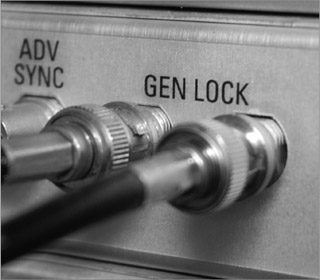
Finally, because the video signal requires great precision in order to work properly, methods of storing and distributing video signals must operate precisely and accurately. For example, it is imperative that the scanning process in cameras and other components be synchronized at every stage of a video signal’s journey through the switcher to all other recording and editing equipment in a production facility. A series of specialized pulses are used for this purpose. The vertical sync pulse coordinates the start of each new frame or field, while the horizontal sync pulse coordinates the scanning of individual lines within a frame or field. The timing and frequency of these pulses depend on what specific format of video is being used. This synchronization is often accomplished by feeding a genlock signal into each device in the control room, as will be discussed later in the chapter.
It is also worthwhile at this juncture to expand a bit on a point about digital signals made in Chapter 1. You will recall that one of the advantages of digital over analog is that digital information can be duplicated and transported with absolutely no degradation in quality. This means that the distribution of digital video signals can be completely transparent with no loss of signal quality as the bitstream travels from point to point. In fact, the quality of the signal is determined at its point of origin (as the visual information is transduced by a camera, for instance) and then can maintain that same level of quality throughout the production process. There will be times during the production process when we purposely sacrifice some quality because of other considerations as we will see, but the mere process of channeling and storing digital signals does not have to introduce distortions to the signal.
Time Code
Another important component of synchronization is time code, which assigns each frame of video a unique numeric designation. Developed by the Society of Motion Picture and Television Engineers (SMPTE), time code gives each frame of video an eight-digit address in the format hours:minutes:seconds:frames, as shown in Figure 10.1.
Time code is used with both digital and analog systems, and with both NTSC and ATSC formats. It consists of electronic signal pulses recorded using a time code generator. A time code reader is then used to read the time code information. Most high-end cameras, video servers, and video recorders are equipped with time code generators and time code readers. Most field cameras record time code automatically as they record video and audio, and this time code can consequently be read by a video server or nonlinear editing system (as discussed in Chapter 11).

The time code generator on a camera is normally set to record run mode, which means the time code clock runs only while the camera is recording. For example, if you stop the camera at time code 00:05:35:15, then begin recording again 20 minutes later, the time code will resume at 00:05:35:16. In free run mode, the time code continues to increment even if the camera is not recording. In this mode, if the camera stops recording at time code 00:05:35:15, then resumes recording exactly 20 minutes later, the time code on tape will pick up at 00:25:35:15. Free-run time code is often used to set the time code to the time of day, allowing the footage to be identified by the precise time it was shot.
Control and Diagnostic Components
A typical studio includes a number of components designed to monitor and ensure signal integrity. The installation and operation of these devices is typically an engineering function, and thus beyond the scope of this chapter. However, it is important you understand that these components exist and know what they are used for.
Control Components
As discussed earlier, pulses are used for the crucial task of syncing all equipment in the studio. The sync generator creates the vertical sync pulse that serves as the reference point for all other equipment in a production facility. Thus, video recorders, switchers, and other equipment have a “sync” or “genlock” connector to read the sync generator’s signal (see Figure 10.2). Since the other pieces of equipment synchronize themselves to the sync generator’s signal, the sync generator is said to provide “studio sync” or “house sync.”
A frame synchronizer is used to synchronize outside video sources to the sync generator. For example, an external satellite feed will likely not be perfectly matched with studio sync. In effect, the frame synchronizer digitally “holds” each frame of video from the external source briefly, then outputs it at the proper time to match studio sync.
A color bar generator sends a standardized pattern of colored bars through the switcher. This signal is then used to calibrate cameras, recorders, monitors, and other studio components. The color bars also are usually recorded onto the beginning of video recordings so that proper color levels can be set at playback.
Diagnostic Components
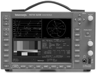
Chapter 9 discussed the use of video monitors in studios to check the picture of various video sources. In many cases, however, it is not enough merely to look at a video signal on a television monitor. To be sure that the signal is properly adjusted at various points in the signal flow, it is necessary to use a waveform monitor and vectorscope (see Figure 10.3), which are sometimes combined into one unit. In many cases, this adjustment will involve internal calibration of a component (such as a switcher) so that it outputs a properly adjusted video signal. This type of calibration, usually undertaken by a studio engineer, generally happens only at certain intervals (a period of weeks or months, perhaps). However, as discussed in Chapter 5, cameras used in a studio have their own camera control unit (CCU) for adjusting their output and are normally adjusted on a daily basis, if not more often.
Composite and Component Signals
In Chapter 5, the three color components (hue, saturation, and luminance) that make up a video signal were discussed. A composite signal combines the chrominance (which, you should remember, includes hue and saturation information) and the luminance (brightness) information. In a component system, on the other hand, the chrominance and luminance information are kept separate and distributed as distinct signals. Many component systems, in fact, use two chrominance signals and the luminance signal.
In the days of analog video, the chrominance and luminance signals had to be distributed via separate cables—for example, you would need a cable for the luminance signal and two cables for the chrominance signals. With digital, all the signals can travel along a single cable but still remain discrete from one another.
Video Encoding and Compression
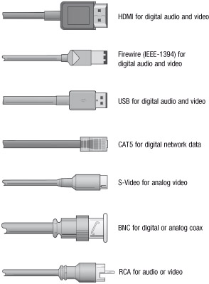
Most professional-level video cameras—especially those designed for studio use—can output uncompressed video via serial digital interface (SDI) connections. In many studio environments, interconnections between various pieces of equipment (such as switchers, character generators, etc.) will be made using SDI cabling with BNC connectors (see Figure 10.4). For distances of up to about 300 feet, SDI signals can travel over coaxial cable; for longer distances, fiber-optic cable must be used. Another system, HDMI (High Definition Multimedia Interface) can also achieve near-SDI throughput levels and can also carry up to 16 audio signals, but is even more limited in distance. The maximum length you can make an HDMI cable without signal loss is about 30 feet. Also, because HDMI connectors do not “lock on” like BNC connectors, HDMI is considered less reliable for professional use. However, you have likely come into contact with HDMI cabling when hooking up home television and Blu-ray systems.
The advantage of using uncompressed signals is that certain production effects—such as chroma keying—can be done more effectively. Uncompressed signals also maintain the absolute highest quality possible throughout the studio production process. However, uncompressed video signals are extremely resource intensive, especially when it comes to bandwidth. For example, the raw SDI signal from a 1080i studio camera can contain 1,500 megabytes of information per second. This is a lot of information, and consequently such a signal would require too much bandwidth for broadcasting systems and too much disk space for practical storage. Thus, once the video signal leaves the control room (if not before), we need to make it less resource-intensive, while still maintaining a suitable level of quality for editing, broadcast, or whatever further production is required. This is accomplished through encoding and compression.
Encoding Digital Video
You have, of course, already seen that video can exist in different formats, such as NTSC or ATSC 1080i. In this case, the term format refers to the resolution of the picture and scanning process, as discussed in Chapter 5. We also use the term to refer to the different ways of recording, channeling, and playing back digital video and audio information. For example, some digital formats are designed for high-quality broadcast signals, while others are designed for use with lower-resolution devices, such as smartphones or portable media players. Here, format refers not necessarily to the specific resolution or scanning process of the video information but rather to the way the information is stored, channeled, and played back.
We discuss some specific formats later in this chapter, but for now we are concerned with encoding, the process of converting from one format to another. Encoding may happen at various stages of the production process, depending on what you are trying to accomplish. Encoding often includes applying some sort of compression to the signal, as discussed below. We refer to specific encoding methods as codecs, which is an abbreviation of compression/decompression. Codecs can be either software based or hardware based. Software-based encoding is performed using a computer and dedicated encoding program—we take a video file, feed it into the encoding program, and it outputs a new file encoded with our chosen codec. Hardware-based encoding is done using electronic circuitry, meaning—in effect—that a signal is plugged into one end of a physical device and comes out the other end encoded with a specific codec.
Two important parameters of encoding are sampling and quantization. Sampling can refer to the process of converting an analog signal into digital, but it is also used when encoding a digital signal from one format to another. The higher the sampling rate, the truer the resulting signal will be to the original. When dealing with digital video, the sampling rate is normally stated as a ratio referring to the number of times the various components of the digital signal are sampled. For example, in 4:2:2 sampling, for every four times the luminance signal is sampled, each of the two chrominance signals is sampled twice. On a 4:1:1 system, each of the two chrominance signals is sampled only once for four samples of the luminance signal. The higher the sampling rate, the higher the quality of the digital signal produced. All else being equal, then, 4:2:2 sampling yields better results than 4:1:1. However, greater sampling rates also require greater bandwidth and larger storage capacity.
Quantization describes how many bits the sampled digital signal is forced into. Remember that a bit (short for binary digit) is an individual digital pulse that can have a value of either 0 or 1. The greater the number of bits, the higher the quality. The most common quantizations for digital video are 8-bit, 10-bit, and 12-bit, with 12-bit allowing the highest quality pictures. Here again, however, the higher quantization level leads to greater bandwidth and storage demands.2
Compression Methods
As discussed, for broadcast and storage purposes we need to make raw digital video signals more compact and less bandwidth-intensive. This is accomplished through the use of compression, which usually takes place as part of an encoding process. Many different compression schemes are available, some of which are designed for specific uses. In general, however, all compression systems work by sampling and analyzing the visual information in a picture and then rearranging it into a more compact form or discarding information that is not needed. Compression systems are termed lossless if they do not lessen picture quality and lossy if they do. In practice, all useful compression systems cause some degradation of picture quality, although it may not be noticeable to most viewers. Compression ratio refers to the size of the original signal as compared to the compressed signal. The higher the compression ratio, the smaller the compressed file as compared to the original. For example, a 16:1 compression ratio will create a signal that requires less bandwidth than a signal created with a 4:1 compression ratio.
The goal of compression is to reach a suitable compromise between picture quality and required bandwidth. To do that, compression systems reduce the bit rate of the digital video signal, meaning that less information is being sent at a time. Bit rate is usually measured in bits per second (bps), kilobits per second (kbps), or megabits per second (mbps). A kilobit represents 1,000 bits, while a megabit represents 1,000 kilobits.3 The lower the bit rate, the less bandwidth that is required.
A given compression system may use either intraframe compression, interframe compression, or a combination of both. Compression methods that use both interframe and intraframe compression tend to achieve much higher compression ratios than those using only intraframe compression.
Intraframe compression analyzes each individual frame of video as an independent entity. For example, if a woman is sitting in front of a plain white background (see Figure 10.5), the compression system might replace all of the individual bits of information that convey the whiteness of the background with a single representation of the white color. Greatly simplified, it is equivalent to the difference between saying, “This pixel is white, this pixel is white, this pixel is white, this pixel is white,” etc., and simply saying, “All these pixels are white.” Intraframe compression also might merge subtle color differences (shades) if they are likely to be imperceptible to the average viewer.
Interframe compression, on the other hand, analyzes groups of frames, ignoring redundant information that doesn’t change from frame to frame. For example, suppose that the woman in front of the white background in Figure 10.5 is sitting almost completely still, moving only her lips, eyes, and head slightly as she talks. From frame to frame of video, most of the picture is not changing. Thus, an interframe compression system would only continue to save the information that is changing from frame to frame—the movement of the lips, eyes, and head. The information that doesn’t change (the plain white background and perhaps the woman’s upper body) would only need to be saved once. It is the same idea as if you printed a 1,000-page printed document and then needed to change the name “Zach Smith” to “Zack Smith” on ten of the pages. You wouldn’t need to re-print all 1,000 pages again, only the ten that you changed.

Figure 10.5 A video shot in which much of the information is redundant and could thus be compressed.
New codecs and compression schemes are continually being developed. As such, this section cannot cover all types of compression that may be available by the time you read this. However, the following section provides an overview of some popular types of video compression.
Motion-JPEG
The Motion-JPEG (M-JPEG) compression system is an outgrowth of the JPEG (Joint Photographic Experts Group) compression scheme for still pictures. You likely already have experience with JPEG images, as it is a popular format for saving photographs and graphics used on web pages.
M-JPEG uses only intraframe compression, with the tradeoff being that it has a low compression ratio. Also, several manufacturers have independently developed their own versions of M-JPEG, resulting in compatibility issues. M-JPEG was the first compression system designed for moving pictures, but it has for the most part been supplanted by other systems.
MPEG-1
MPEG-1 is named after the Moving Pictures Experts Group, a consortium formed after the development of JPEG to work on a more efficient compression system for moving pictures. MPEG-1 was designed to record VHS tape-quality, standard-definition video onto CDs. MPEG-1 can still be used, but it has been largely supplanted by newer MPEG versions.
MPEG-2
MPEG-2 has been the most widely used compression scheme for high-quality digital television. MPEG-2 doesn’t define a single standard but rather defines a series of standards, including those used to record DVD video discs and Sony’s XDCAM format. MPEG-2 has been popular for use in high-definition compression, but it has been supplanted in many applications by the more efficient MPEG-4.
MPEG-4 and H.264
MPEG-4 was initially designed for delivering interactive multimedia content, but due to its effectiveness it has grown to be used in many types of video applications. One subset of MPEG-4, denoted as H.264 or MPEG-4 AVC, is particularly effective at achieving impressive bit rate reductions with relatively inexpensive equipment. For that reason, many video cameras record using MPEG-4 AVC technology. However, various versions of this technology have been developed by manufacturers. These include AVCHD, developed jointly by Panasonic and Sony; Sony’s NXCAM; and Panasonic’s AVCCAM and AVCHD Pro.
H.265
H.265, or HEVC (High Efficiency Video Encoding), is the successor to H.264, developed to handle video resolutions of 4K and beyond. H.265 promises twice the compression rate of H.264, along with better video quality. However, as this is being written, not all software and hardware supports playback of H.265-encoded video.
Containers
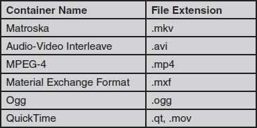
A container is a digital file format designed to hold video and other information. For example, a container might include the compressed video file, metadata about the file (discussed below), subtitles, and other information. Containers are normally not compression-method specific, meaning that a given container could be used for video encoded by MPEG-4 or MPEG-2. Popular container formats for video are listed in Figure 10.6.
Storage Technologies
A number of options are available for storing digital audio and video data. In general terms, these options can be grouped into three categories: hard drives, optical discs, and solid state memory. Each of these types has advantages and disadvantages that make each most suited to a particular storage function. Generally, in the acquisition phase of video production, such as recording field footage on a portable camcorder, solid state technologies are used. In the long-term storage and editing phases of production, hard drives are most common and are likely to remain dominant for the foreseeable future. However, solid state technologies seem to be the next step in editing and perhaps for long-term storage as well.
Hard Drives
First developed by IBM in the 1950s, hard drives consist of a series of motor-driven platters in a protective enclosure. One or more read/write heads (not unlike the needle on a vinyl record) ride just above the surface of the platters and magnetically read and write data on them. Hard drives are a mainstay on personal computers, of course, and they are continually improving in storage capacity, read/write speed, and overall cost.
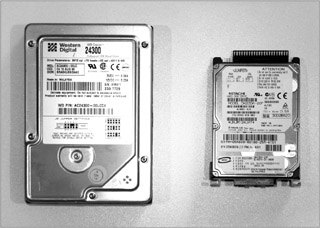
Hard drives are manufactured in a variety of sizes, called form factors, ranging from 3.5 inches to less than an inch. The hard drive in a typical desktop computer system is a 3.5-inch unit, while smaller 2.5-inch units are used in laptops (see Figure 10.7). The 3.5-inch units are usually found in video servers, as discussed below, while 2.5-inch and smaller units are normally used on portable camcorders. Not only are smaller hard drive form factors more portable, they also tend to use less power, an important consideration in situations like field production where batteries are used.
The main advantage of hard drives over other tapeless media is their capacity-to-price ratio. If you have shopped for computers over the past few years, you have probably noticed the escalating storage capacities of low-cost hard drives. The same rate of innovation has improved hard drives for video storage as well. The downsides to hard drives, however, are their power consumption and durability. For these reasons, hard drives are increasingly used in video servers and other applications where AC power is available and portability is not an issue.
Optical Discs
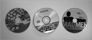
Optical discs work on a similar principle as hard drives, except that the system is not enclosed and uses removable discs for recording and playback. Optical discs come in a variety of formats, including CDs, DVDs (digital versatile discs), and Blu-ray. The main difference among the formats is storage capacity—all three discs normally share the same 12-centimeter diameter form factor (see Figure 10.8). CDs can hold less than 1 megabyte of data, DVDs can hold up to 8.5 gigabytes, and Blu-rays currently hold up to 128 gigabytes.
Optical discs share the same power consumption and durability shortcomings as hard disks. They are also limited in terms of storage capacity; a 50-gigabyte Blu-ray disc, for example, can hold only about four hours of high-definition video. Optical discs are also sensitive to being scratched or broken if mishandled. Optical discs are used most often for distributing finished video programs.
Solid State Media
Solid state media use electronic circuitry to store data. There are no moving parts, so power consumption is lower, durability is better, and size can be smaller. Solid state media come in a variety of formats; some are specifically designed for video use, and some are designed for more general applications. You are probably already familiar with at least one form of solid state media if you use a USB flash drive on your computer. Similarly, most portable music players now use solid state memory, as do tablet computers and smartphones.
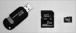
Figure 10.9 shows some of the main types of solid state media used in video production. USB drives are not often used in video production, but they can be useful in transporting video data from a camera to an editing computer or from a server to another computer. Secure Digital (SD) memory cards have become the standard for still photography and are also increasingly being used in video cameras as well. These highly portable and standardized cards are available in a variety of sizes well into the hundreds of gigabytes, and they will likely soon move into terabytes. The micro-SD form factor is even smaller but is more limited in data capacity. A similar format, Sony’s Memory Stick, has been used in some of that company’s video cameras but has been ignored by most other companies in favor of the more common SD format.
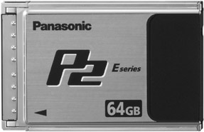
Another proprietary format is Panasonic’s P2 (Professional Plug-In). (See Figure 10.10.) P2 cards can store data in a number of different quality levels in both standard-definition and high-definition formats. A 64-gigabyte P2 card, for example, can store more than four hours of standard-definition video and a little more than an hour of high-definition video.
At this point, the only significant downside to solid state media is cost. Although storage capacities for all types of solid state media are on a constant upward trend, solid state media still costs more per gigabyte than either hard disks or optical discs.
Video Servers
While the previous storage methods are important in capturing and storing individual segments of video, they are not as useful in situations where a vast amount of video needs to be shared with many different people. This is where video servers come in. Video servers have been mentioned throughout this chapter, and they are an increasingly important component of the video production process. You can grasp the general idea of a video server if you think of it as a very large hard drive. Although most video servers are specially designed to input, store, and output digital video, they perform the same basic function as the hard drive in your computer: storing digital data.
Putting Video on Servers
Servers allow you to access the exact piece of video you want almost instantaneously. In fact, the determining factor in how fast you can get what you want from a video server is often how well you’ve kept track of what’s recorded on it. For that reason, video production professionals are increasingly concerned with asset management, the process of cataloging and using video on servers in the most efficient manner possible.
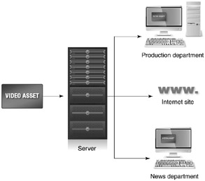
For example, consider a local television station whose production department shoots footage of a local charity event to use in a public service announcement. Once that video is placed on the server, it becomes an asset that can be made available to a number of different entities. As shown in Figure 10.11, the news department may wish to edit together some of the footage to use in a story in that evening’s nightly newscast. Later that day, the production department could access the footage to edit the public service announcement. The station might also make some footage of the event available over its website. Another important capability video servers offer is the potential to do all of these things at the same time. If the footage existed only on a disc or tape, it could be used by only one person at a time (unless, of course, you took the time to make extra copies).
A valuable aid to asset management is the use of metadata, which allows additional information to be recorded with the video. For example, you can give the video footage a title and description (“Footage of the United Way celebrity dinner”) and note the date it was shot, who shot it, and even what equipment was used. Later, the footage can be accessed easily by searching for one or more of these parameters.
Getting video on a server can still be rather time-consuming, although technology is making the job go faster. The process of putting video on a server is called ingesting, and it happens in a number of different ways. The easiest way is to simply copy the video files onto the server. This works the same way as if you copied your class notes from your home computer to a removable drive. Video is recorded onto tapeless media essentially as very large data files, so these files can be copied to and from the server rather easily. Of course, very large, high-definition video files can take a long time to copy, but the process is straightforward. A number of software- and hardware-based enhancements make the job even easier; for example, a video camera operator may return from the field with a solid state card full of video from the morning’s shoot and then simply plug the card into a computer in the office. After a few keystrokes labeling the footage, the date, and other desired metadata, the system begins copying the footage to the server.
Using Servers
An ever-increasing number of video servers are becoming available, offering a wide variety of functions, quality levels, and storage capacities. Some servers are designed specifically for use with one compression system, while others can use a variety of types. More expensive systems also have the capability to input and output multiple bitstreams simultaneously, meaning that video can be going into and coming out of the system at the same time. In live production environments, especially sports coverage, the live slow motion (LSM) server and controller has become an essential component. As discussed in Chapter 11, the LSM server records the output of several different cameras simultaneously and allows the operator to quickly re-call multiple camera angles and replays.
Most servers consist of two main parts: a record/play unit with a computer interface that allows the operator to access and manipulate video information, and an array of disk drives used to store the data. Some servers, however, come only as storage units. These types use some other piece of equipment (such as a switcher) as an external controller. One popular method of providing the storage and speed capacity required to work with digital video is RAID (redundant array of independent disks). RAID uses a group of hard disks wired and controlled as if they were one large, very fast hard disk.
Servers can be connected together (and to other video components) in a network system, and the faster the network system—meaning the higher the bandwidth—the better. One network system that has become popular for video storage is called fiberchannel; it allows data transfer speeds of up to 200 Mb/s. Routers allow the digital signal from one source to be sent to a number of different locations. Such systems allow servers to share digital bitstreams and to move digital data from place to place within a production facility or across long distances.
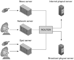
Figure 10.12 shows how a local television station might use a series of servers to meet its needs. The news department would have its own server, networked to allow different news department personnel to access information on it. Footage shot in the field would be ingested into the server, then would be available for editing into roll-ins. The finished roll-ins would then be fed to the station’s main playout server. Commercials would be stored on a spot server (named for commercial “spots”) and transferred to the playout server when it is close to the time they are to air. Commercials would be ingested into the spot server over a satellite connection (for national commercials) or directly from the production department (for locally produced commercials). Much of this processing can be automated; the servers can be programmed to exchange the relevant data files at appropriate times. Programming from the broadcast network is ingested via satellite and stored on a dedicated server until it is time for it to air. At that point, it is transferred to the playout server. Live network programming, of course, can still be aired by the station; this programming would simply come directly from satellite and bypass the server systems. In addition, a dedicated server can provide video over the Internet, either “live” in real-time simulcast with the station’s broadcasts or as a series of individual files that can be downloaded by users on demand.
Preparing Video for Multiple Devices
For approximately a half century, nearly all video production was done with a single destination device in mind: an NTSC standard-definition television set. That set may have been a 27-inch console in a family’s living room, a 12-inch portable unit in a teenager’s bedroom, or a 48-inch projector in a corporate boardroom, but it was single-format television all the same. High-end Hollywood drama producers, local commercial producers, and corporate video producers all created content for the NTSC, 640-by-480 interlace scanning television system (at least in the United States).
However, as discussed in Chapter 1, today, video can take many different forms and be consumed on many different types of devices. There is still a market for high-quality video that will end up on broadcast or cable networks, or perhaps Blu-ray discs; but there is also a growing market for video that doesn’t need to be encoded in the highest quality settings. For example, a video designed to be viewed over the Internet with a smartphone or other device with a small screen does not need to have the same level of picture quality as that designed to be viewed on a 60-inch, high-definition television set.
This change potentially affects all aspects of video production, from how productions are planned to how shots are framed and footage is edited. However, the primary issues are those involving the recording, channeling, and playback of digital video for devices other than televisions. This section provides some basic guidelines and tips for preparing video programs, especially for viewing over Internet connections and on portable devices.
Viewing Video Files
The two basic ways to view video files over the Internet or another wired or wireless system are downloading and streaming. When downloading, the video file is sent to the user in pieces, called packets, which are then reassembled by the user’s device and saved. The video cannot be viewed until the entire file has been downloaded and saved. For a very large file, this might mean the user cannot see the video for several minutes, or perhaps hours. Streaming also sends the data in packets, but the packets are structured so that the individual frames of the video are sent sequentially. This means that the user can view the file and hear its audio as it is coming into his or her device. Most streaming formats, in fact, do not actually save the complete file to the user’s device at all—instead it is gone after the user views it. Streaming has the major advantage of allowing the user to begin watching the clip almost immediately, with no need to wait for the entire file to finish downloading. Thus, most video content sent over the Internet and other networks uses streaming technology.
Encoding Parameters
A number of software programs are available for encoding and compressing video, including Adobe Media Encoder; Apple Compressor; and Handbrake, an open-source program available for download on either Macintosh or Windows platforms. The Adobe and Apple encoders can run as freestanding programs, and they also integrate into the companies’ editing programs (Premiere Pro and Final Cut Pro, respectively). As discussed in Chapter 11, when you are ready to export a finished product from one of these editing programs, the encoding program is started automatically.
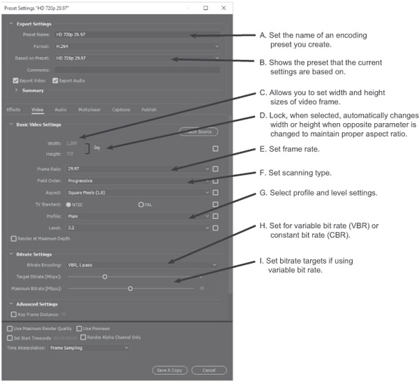
When we are preparing a video to be viewed over the Internet, one of our main concerns is bandwidth. Specifically, we want to keep bandwidth (and, by extension, overall file size) as small as possible without sacrificing too much quality. If our bandwidth settings for a video are too high, it can cause the video to transfer too slowly, causing stilted and erratic playback. High bandwidth settings will also eat into end users’ data plans. Thus, preparing video for consumption on the Internet involves finding the proper balance between bandwidth and quality. The following section presents an overview of parameters that can be manipulated to achieve the desired results for finished video programs. Figure 10.13 shows how these parameters can be set in Adobe Media Encoder.
Type of Compression
As noted previously in this chapter, there are a number of different types of compression available. For most work designed for consumption over the Internet, you will find that H.264 is a good starting point. For 4K and higher resolution video, try H.265.
Bit Rate
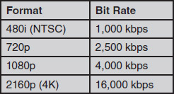
As noted previously, bit rate indicates the overall bandwidth of the signal; it is an indication of how much information is flowing through the electronic “pipe” each second. Bit rate will indicate the overall bandwidth (and by extension file size) of a given video file. The higher the bit rate, the greater the bandwidth requirements and the larger the file. Figure 10.14 shows suggested bit rates for various video formats; however, these can merely be starting points—you may find that different bit rates work better for your specific application.
Constant bit rate (CBR) maintains a constant rate of data flow no matter what the video or scene. For example, a 10-second scene with lots of movement and action will have the same overall bit rate as a 10-second still picture with little or no movement. Variable bit rate (VBR) varies the bit rate—within a range you can set—according to what kind of video is being encoded. Using VBR, for example, a scene with lots of movement would likely have a higher bit rate than the one that has little movement. The most efficient way to encode a given piece of video is sometimes “2 pass” VBR encoding. With this setting, the encoder runs through the entire piece of video and determines the portions that need the highest bit rate and those that need the least. Then on the second pass, it encodes the video at a variable bit rate most suited to each part of the video.
Frame Size
Frame size is a measurement of the frame’s width and height. Although it is possible to change width and height independently, you should usually change them in unison so that the frame maintains its proper aspect ratio and does not look “stretched” either vertically or horizontally. The “lock” icon on Adobe Media Encoder (see Figure 10.13) will ensure that when you change either width or height that the other dimension will change accordingly. If a video is designed solely to be viewed on a small screen, you can lower the dimensions to match the size of that screen. However, if that video is viewed on a large screen, it will likely look very blocky.
Frame Rate
Frame rate measures the number of frames per each second of video. As noted in Chapter 5, normal frame rates for broadcast television are 30 or 60 frames per second. For online use, you can consider lowering the frame rate depending on the specific video. Video that has a lot of movement should probably not have a lower frame rate, but video of a talking head interview can likely have a lower frame rate. Although frame rates as low as 15 frames per second can work well for Internet video in some cases, anything lower than that should be used with caution. At very low frame rates, even small amounts of movement in the frame can look stilted and jumpy.
Other Parameters
For MPEG-2 and MPEG-4 compression, you can also set profiles and levels that affect the specific technologies actually used to compress the video. You can also, in most programs, select from several (at least) different pre-sets, which automatically select profiles, levels, and other settings appropriate for a given application. For example, an encoding program may have pre-sets available for uploading a video to YouTube or for a specific type of phone. You can also set specific parameters for audio, such as the sampling rate and whether the audio is mono or stereo.
Encoding Techniques
As you can see, there are a lot of variables involved in encoding and compressing video. In some ways, it is like what “tuner” auto enthusiasts do—they try to find the right combination of fuel mixture, suspension settings, and other factors to make their cars go fastest. Sometimes, the best way to find out which settings work best is to just start experimenting.
To start experimenting, you can save time by just exporting a 5- to 10-second clip in your editing program (see Chapter 11) that has a lot of movement in it. Then, use that clip to try out different settings. Since movement in the frame creates the greatest challenge for compression, you can be certain that if the part of your program with a lot of movement looks good after compression, the rest of it will look good, too. It also raises another good point about shooting video designed for use in highly compressed environments—you should do your best to avoid camera shake and other unnecessary camera movements as these create the potential for making the compressed video look blocky, jumpy, or distorted.
Focus Points
After reading this chapter, you should know . . .
- The basic components and special attributes of video signals.
- The advantages of digital signals over analog signals, and the basic methods of encoding digital video.
- The importance of compression in digital video, and the major methods of compression.
- The basic design and operation of digital video servers, including the concepts of ingesting and asset management.
- Other digital-based storage options for video, including optical media and memory cards.
- The basic options available for creating digital video files for use with computers and portable devices.
Review
- What are the basic attributes of video signals? How do these attributes affect how video information is channeled, monitored, recorded, and played back?
- What are the basic methods of encoding digital video? What do the terms sampling and quantization mean, and how do these concepts affect the quality of the resulting digital video signal?
- Discuss the major compression methods. What are the advantages and disadvantages of each? How prevalent is each method in the industry?
- What are some of the parameters that can be set for video formats designed for use on the Internet?
On Set
- Analyze the process of gathering, editing, and outputting video footage at your school. How is footage gathered (tape, hard drive, solid state media)? How is it edited (switcher, nonlinear editing)? If it is edited on nonlinear systems, how is the footage ingested? What are the options for outputting?
- Take a video clip and experiment with different types of compression. Note any differences in the quality of the versions and indicate the file size of each.
Notes
1In the 1970s, a system of recording analog video onto discs was developed for home use. This LaserDisc system featured better picture quality than VHS tape, but it was not recordable and so never caught on with home users. Also, some companies developed analog disc systems for recording video effects and editing. However, in practice, nearly all of these systems have been replaced by superior digital-based equipment.
2Interestingly, the human eye is much more forgiving than the human ear when perceiving a quantized analog signal. While 10-bit quantization (and certainly 12-bit) can produce a seemingly flawless visual picture, audio with the same perceived quality level requires at least 16 bits, and perhaps as many as 24.
3You may note the difference here between bits and bytes. A bit represents an individual on-off pulse of a digital signal, as discussed in Chapter 1. A byte represents a group of 8 bits. So, while the storage and memory capacity of most computer devices is measured in bytes (and kilobytes, megabytes, gigabytes, and so on), bit rate is measured in bits (and kilobits, megabits, gigabits, and so on).