It’s no exaggeration to call the switcher the nerve center of a video production facility. More than any other piece of equipment, the switcher is central to the creation of video programs of all types, and it is literally the connecting point for most other pieces of video equipment in a studio. Although switchers are also used in postproduction editing facilities, as discussed in Chapter 11, this chapter concentrates on the operation of the switcher in a studio production environment. The general operation of the switcher is the same in either situation.
The video switcher serves a number of different functions. First and foremost, it is an editing device that facilitates the time-ordered sequencing of inputs within a live or live-to-recording video production. To do this, the switcher serves a channeling or routing function as it selects a video source from all the available inputs, such as cameras, video servers, remote feeds, and computer-generated graphics. The switcher also functions as a selecting and altering component that can combine two or more visual sources in a number of different ways. Through the use of digital video effects (DVE), a switcher can become a special effects generator (SEG) with the capability of altering the appearance of video inputs.
The discipline of operating switchers includes understanding how they are connected to other equipment and the basic concepts of their design. This understanding will make the techniques of achieving various effects using a switcher much easier to master. Despite the wide range of switcher types and levels of complexity, a few basic principles of design, function, and operation are common to all units. Once you understand these basic principles, you can more confidently approach the operation of the advanced switcher units found in professional production environments.
Switcher Basics
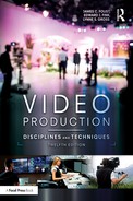
Figure 9.1 is a simplified block diagram of how a switcher might be connected in a typical studio. As you can see, several video sources are connected as inputs to the switcher—in this case there are three cameras, two video servers, and a character generator, which is used to put words and graphics on screen. Usually, all video sources in a studio will be run through the switcher, and in advanced settings these might include several cameras, satellite feeds, digital storage devices, and various graphics computers.
The switcher shown in Figure 9.1 has two outputs:
- The program line is the main output—the one that goes over the air or is recorded. A program monitor allows studio personnel to see the video signal that is being put out by the switcher.
- The preview line is a separate output that is used to set up video effects before they are put on the air. For example, you might want to see what a graphic placed over a camera shot looks like before it is actually put on the air; a preview monitor allows you to do this.
In more advanced facilities, a number of preview lines and monitors may be available to set up particular special effects.
Monitoring Multiple Signals
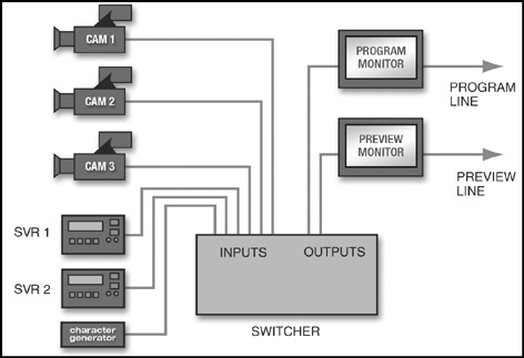
Video monitors in the control room are essential to the proper use of the switcher, as well as for camera operations. Even in a moderate-size studio, there may be up to a dozen different monitors, each performing an important individual function. Each studio camera, graphics generator, and video recording source, for example, will have a small individual monitor. In a live broadcasting situation, a larger air monitor always shows the actual broadcast picture, which is received over the air from the transmitter or another source. The various monitors will have their functions labeled, such as “CAM 3” for the camera 3 video or “PROMPT” for the teleprompter output. This labeling can be done with a low-tech method, such as a piece of tape and a marker, or electronically with under-monitor displays, as shown in Figure 9.2.
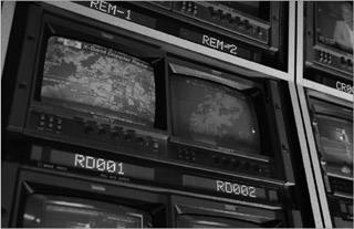
In many of the newest studios, the various individual monitors have been replaced by large flat-screen monitors that can be set up to show various outputs. In Figure 9.3, for example, a large monitor shows various inputs, a clock, and the program and preview outputs. These large monitors take up less space than individual monitors, and they can be programmed to display different outputs as needed.
Portable and Computer-Based Switchers
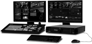
Increasing digitization has allowed switchers to become smaller. A number of manufacturers make portable switchers, which can be transported and set up with relative ease. One example is NewTek’s TriCaster 460, which is based on specialized hardware with software that runs on the Windows operating system (see Figure 9.4). The TriCaster includes a switcher, digital effects, nonlinear editing, and graphics capabilities. Switching is accomplished by pressing virtual buttons on the computer screen or by using an optional switching attachment featuring physical buttons.
Master Control and Routing Switchers
Less-sophisticated switchers are found in the master control area of television stations or other broadcast facilities, where they are used to select various video sources such as network feeds, commercials, and studio output. Even simpler units, known as routing switchers, are used to distribute video sources within a studio. For example, a simple routing switcher may be used to select which video input is viewed on a particular studio monitor.
Fundamentals of Switcher Design
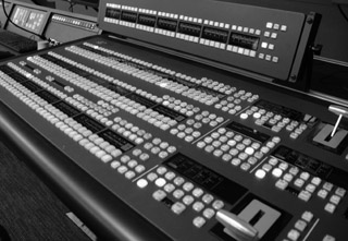
A video switcher, especially a unit as elaborate as the one shown in Figure 9.5, can be an intimidating piece of equipment. There may be literally hundreds of buttons, dozens of knobs, several LED display readouts, and numerous other controls. It is well beyond the scope of this chapter to equip you to operate such an advanced switcher, but a number of design and operation principles are common to all switchers. If you gain a basic understanding of how switchers are designed and operated, and then practice on simpler switchers, you will eventually be prepared to tackle advanced units. At that point, the sea of buttons, knobs, and levers will make a lot more sense to you and indeed will become familiar tools that you’ll use routinely to achieve your production goals.
Buses
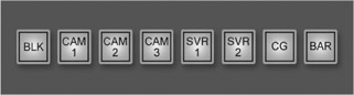
The main operational controls of any switcher are the rows of switches called buses or banks. Each bus contains a group of buttons, with one button for each video input and with additional buttons for other functions. Figure 9.6 shows a bus for the sample switcher shown in Figure 9.1. In addition to the video inputs, this sample bus also shows a black button, used to select a fully synchronized black signal, and a button for color bars. Only one signal source per bus can be pressed down at a time—when one button is pushed, the previously depressed button is automatically released. Therefore, each bus can have just one signal punched into it at any given moment.1
The number of buses, their functions, and their design vary from switcher to switcher. However, a few types of buses are common to most switchers. The first of these is the program bus, which selects the video input that will be put out over the program line. If we were to consider the sample bus shown in Figure 9.6 as the switcher’s program bus, we could select video outputs by pressing the appropriate button on this bus. For example, if we want to have camera 1’s output go over the program line, we would press the “CAM 1” button. To change the shot to camera 2, we would press the “CAM 2” button. The “CAM 1” button would then deselect, and camera 2’s output would be seen on the program line. Changing from one shot to another is called performing a transition. The simplest type of transition, discussed earlier, is the cut, which instantaneously replaces one picture with another. You can perform cuts by simply depressing other buttons on the program bus. For example, you could cut to camera 2, then camera 3, then back to camera 1 by pressing the appropriate buttons on the program bus.
Using the Preset Bus
To perform a transition other than a cut, we need to add one or more additional buses and have a method to gradually move between the buses. This is because any transition other than a cut will have a specific duration, or speed at which it occurs. Thus, we need to have a way of controlling that duration, in effect determining how long the transition will take. Cuts, which happen instantaneously, effectively have no duration.
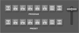
Figure 9.7 shows a new bus added to the sample switcher, plus a fader bar we use to transition from one bus selection to the other. The program bus still determines the video source that is going out over the program line, but now we use the preset bus to ready the next video input. The preset bus also normally has its own video monitor, so that the operator can preview the input selected on the preset bus before it is actually put on the air.
The use of two or more separate buses allows us to perform transitions such as dissolves (in which one picture gradually fades into another), wipes, and advanced effects; the specific transition is determined by selecting the appropriate controls elsewhere on the switcher. Wipes and advanced effects will be discussed later in this chapter; for now, let’s assume that you want to perform a dissolve.
The simplest type of dissolve is a fade-in from black signal to a video input, commonly used at the beginning of a program. For example, let’s say you want to begin on black signal, then fade in to camera 1. You set up the buses as shown in Figure 9.8a: You place the fader bar in the fully downward position and select “BLK” on the program bus and “CAM 1” on the preset bus. When set up in this manner, you will see black signal over the program line. When you move the fader bar upward, the input selected on the preset bus gradually fades in, eventually completely replacing the original signal on the program bus. At completion, as shown in Figure 9.8b, “CAM 1” is selected on the program bus, and camera 1’s signal is now seen on the program line. The speed at which you move the fader bar determines the duration of the dissolve between buses.
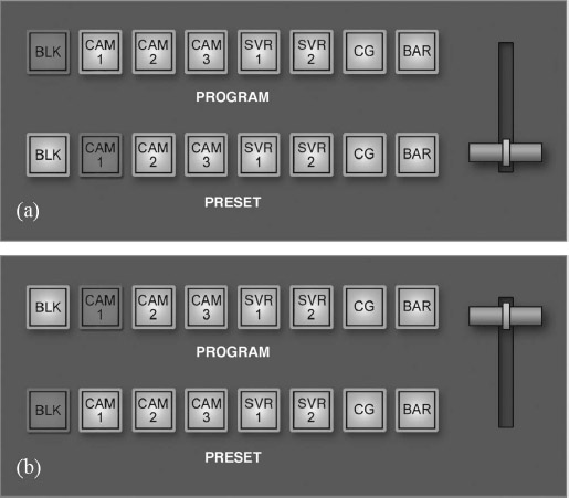
It is important to point out that on switchers that use preset buses, the physical position of the fader bar does not correspond to which bus is selected. The fact that the fader bar is in the down position does not mean that the preset bus selection is currently on-air. The program bus is always on-air, and moving the fader bar—whether down to up or up to down—always replaces the program bus input with the preset bus input. It also—as you can see in Figure 9.8b—replaces the preset bus selection with the previous selection on the program bus. Thus, the fader bar essentially flip-flops the program and preset bus selections.
You can fade out to black at the end of the program in much the same way you performed the fade-in from black. To do this, you would simply select “BLK” on the preset bus, then move the fader bar to opposite its current position. On the program monitor, you would see the picture gradually fade to black, the duration of the fade determined by how quickly you move the fader bar.
If in the process of performing a dissolve between video inputs you simply stop the fader bar at its midpoint, you will have a superimposition, or super. This is simply two pictures that are blended together. You have probably seen this effect in live musical performances, where, for instance, a close-up of a guitar player’s hand is blended with a wider shot. You can “hold” the super as long as you wish by simply leaving the fader bar at the midpoint.
Wipes
For some transitions between two consecutive video sources, neither a cut nor a dissolve is suitable. An example might be if you want to draw special attention to a particular piece or pieces of video. The wipe transition often accomplishes this perfectly—by letting the viewer see portions of both video sources as the separation line moves across the screen. Used excessively, the wipe calls attention to itself as a gimmick, but, when used with discretion, it can become an important part of your visual vocabulary.
Many switchers have dozens of patterned wipe designs, including the traditional vertical line moving horizontally across the screen (or a horizontal line moving vertically down the screen), diagonals, diamonds, circles, boxes, and other shapes. Most switchers also have at least some capability to create and manipulate the borders that appear between wipe effects. These borders can be made different colors and thicknesses and also can be set as either “hard” (creating a sharp delineation between the border and the video) or “soft” (where the border fades into the video).

Just as dissolves can be halted at midpoint to create superimpositions, wipes also can be halted at midpoint to create a number of effects. One common application of a “suspended” wipe transition, the split screen, combines two pictures with either a horizontal or a vertical (or occasionally diagonal) line separating the screen into two distinct areas—with a different picture (from separate cameras or other video sources) in each part of the screen, as shown in Figure 9.9. By positioning the fader bar, the relative sizes of the two pictures can be adjusted.
Another useful special effect is the spotlight, which enables the operator to dim the entire screen except for one circle of brightness, which can be shaped, changed in size, and positioned anywhere on the screen with a joystick. This effect can be useful for calling attention to a particular part of the screen, highlighting a particular person in a group picture, for example. It also is possible to create a corner insert effect, which places the inserted camera picture in any quadrant of the screen, as shown in Figure 9.10. Again, the exact size and proportion of the corner insert can be adjusted by using the fader bar. However, as we will see later in this chapter, the corner insert effect is better accomplished using digital video effects.

Keys
We have already discussed how a suspended dissolve can create a superimposition that blends two separate video sources. A key effect also blends two or more sources, but it actually “cuts out” part of one source and replaces it with another source.2 In this way, both sources maintain their brightness level, unlike with the superimposition, which weakens the level of both sources. Keys are most often used to place lettering or graphics over a video signal; the switcher “cuts a hole” in the video signal and inserts the lettering (from a separate video source) into it. Figure 9.11 illustrates the difference between a super and a key.
The example shown in Figure 9.11 (bottom) is called a self key (also known as a luminance key or internal key) because the dominant brightness level of the lettering cuts its own electronic pattern in the background picture. In many such effects, a wipe pattern is used to create the outline shape, and another source is used as an input to fill the hole. Another version of this effect, known as an auto key or external key, uses one video source to establish the external shape of a letter or figure—in effect, stamping out an image much like a stencil might cut out a shape. The key effect then uses another source to fill in the picture and color of the “stenciled-out” part of the design. Figure 9.12 shows an example of this effect.
Keys can be created in a manner similar to dissolves and wipes. For example, you could select a key effect on one of the buses, then set up the appropriate video inputs. Some switchers have one or more dedicated key buses that are used to select key backgrounds and overlays.


Chroma key is a process in which a specific color—rather than a graphic design or pattern—is used as the electronic key to cut out part of the picture. Any color can be designated as the key color; however, blue and green are the most often used because they are farthest from any skin tones. This is why chroma keys are sometimes called “green screens” or “blue screens.” Wherever the foreground or key camera detects the designated hue (and brightness) in its picture, that video information is discarded, and background picture signals are supplied from a second source, such as a graphics unit, camera, or video server.
Probably the most common example of the chroma key process is seen nightly on the local weathercast. The studio camera has a shot of the weathercaster standing in front of a green background (but not wearing any green item of clothing). Through the switcher, this picture is combined with the computer-generated local or national weather map that includes animated effects such as cloud movement. The result gives the impression that the weathercaster is standing in front of a map.
Successful use of chroma key requires precise coordination of various technical elements. The cameras, switcher, and graphics equipment need to be precisely adjusted, and the lighting must be even. Slight problems in any of these areas can lead to “tearing” of the foreground image, an obvious border around the foreground figure, discoloration, or indistinct contours. Many of these drawbacks have been overcome by newer systems, such as Ultimatte,3 which are used in most major professional studios. These advanced systems don’t actually cut out the part of the picture colored blue or green but rather blend the second video source with the first. The level of blending is determined by the intensity of the background color—this makes it possible, for example, to use smoke effects or translucent objects in the foreground video source.
Mix and Preview Buses
Many switchers have additional buses, called mix buses or mix/effects (M/E) buses, to facilitate dissolves, wipes, and other effects. Mix buses are actually sets of two buses on which transitions or effects can be set up in advance, then selected on the program bus. The necessity of such buses becomes apparent when you think about the limitations of the sample program/preset bus switcher we have been using as an example. Using this switcher, there is no way to go directly from a shot on camera 3 to a corner insert effect or split-screen effect using cameras 1 and 2. Think about it: your only choice would be to start on camera 3, select camera 2 on the program bus, then quickly set up the corner effect on-air; you would have no way of setting up the effect before it went out on-air. Obviously, this would look sloppy and would be confusing to the viewer.
Mix buses not only allow you to set up effects in advance, then seamlessly put them on the air; they also allow you to see what the effect will look like before it is put on the air. This is normally accomplished through the use of one or more preview lines, discussed at the beginning of this chapter. On these preview lines (connected to video monitors), you can see an effect without putting it on the air. Depending on the switcher, each mix bus may have its own preview line, or the preview function may be facilitated by a preview bus that allows you to select the input(s) you want to preview. On some switchers, the preset and preview buses are combined into a single bus—thus, the input selected there will replace the input currently on the program bus when you move the fader bar, and you will be able to preview that input before putting it on the air.

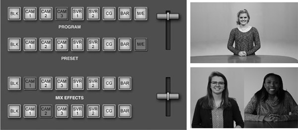
Figure 9.13 shows a mix bus added to our sample switcher and the various buses set up to prepare for a split-screen effect. Camera 3 is on the air now—its input is selected on the program bus, and we can see it on the program monitor. The effect is ready to go on the M/E bus, as we have selected camera 1 on the top row and camera 2 on the bottom row and moved the M/E bus’s fader bar to a midpoint position. Although not shown in the diagram, we have selected a horizontal wipe transition for the M/E bus. We have selected “M/E” (mix/effects) on the preset/preview bus, because the next thing we want to see on air is the effect from the M/E bus. This also allows us to see what the effect will look like on the preview monitor.
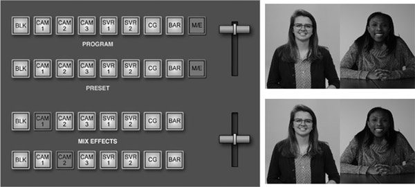
When we’re ready, we can put the effect on the air by pressing the “M/E” button on the program bus, thereby cutting from camera 3 to the split-screen effect, as shown in Figure 9.14. The program monitor now shows the effect from the M/E bus. The preview monitor still shows it as well, since we have not taken the effect off the preset/preview bus.
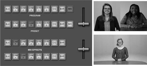
If we want to dissolve to the split-screen effect instead of cut, we can do so by selecting a dissolve transition between the program and preset/preview buses, then moving the main fader bar to its opposite position, as shown in Figure 9.15. By comparing Figures 9.13 and 9.15, you can see that the end result is much the same, with the exception that the fader bar is now in the opposite position and the program and preset/preview buses have flip-flopped in Figure 9.15. We now see the input from camera 3 on the preview monitor. There was no flip-flop in Figure 9.14, because we selected the M/E input directly on the program bus.
Downstream Key and Fade Functions
Although we have discussed using the M/E buses on a switcher to create keys and fades, many switchers have built-in functions for accomplishing these effects. These are called downstream effects because they happen after the signal has passed through all the buses and just before the signal leaves the switcher. The main advantage of the downstream functions is that they allow you to accomplish the effect without tying up one of the M/E buses. They also provide a quick and easy way to accomplish key and fade tasks that are used quite often in video productions.
For example, on a switcher equipped with a downstream keyer, you simply select the source for the key effect, then press the “downstream key” (or “DSK”) button. The switcher keys the source over whatever other video effects have been set up using the normal buses. Similarly, a switcher may have a master fade button that, when pressed, simply fades the video to or from black.
Operational Techniques for Video Switchers
Now that we have discussed some of the general principles of how video switchers are designed and operated, we can move on to some actual operational examples. To do this, we will refer to a relatively simple production switcher, shown in Figure 9.16 (and see also video examples on the Video Production website). It is similar in its basic design to switchers you might find in a variety of production environments.
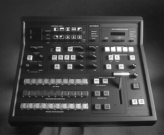
Switcher Overview
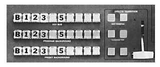
A careful look at Figure 9.16 shows that this particular switcher uses a program and combined preset/preview bus design, similar to the sample switcher discussed in the previous section. It also has a key bus, located above the program bus. The switcher can accept up to eight video inputs in addition to black and color bars; you will notice that each bus, then, has a total of ten buttons. To the immediate right of the three buses is the fader bar, along with several controls for selecting the transition type. Controls for the downstream keyer wrap around the fader bar, above it and to the right. In the middle of the switcher, above the key bus, are controls for performing other types of key effects, as well as controls for creating background colors.
The wipe controls are located in the upper left corner of the switcher, including a joystick to position “spotlight” and other wipes. Finally, at the upper right of the switcher are the auto transition controls, which allow the operator to set the switcher to perform automatic transitions of a desired length.
Performing Dissolves
Let’s follow an example of a simple dissolve from camera 1 to camera 2. We first go to the transition section, shown at the right-hand side of Figure 9.17, and press the MIX button just above “transition type,” because a dissolve means mixing two signals together. We also press the background (BKGD) button above the “next transition” section of the effects transition group of controls. (We will look at this in more detail later.) Next, with the fader lever in the upper position, we press the camera 1 button on the upper program bank and the camera 2 button on the lower preset bank. The camera 1 button on the program bank will glow brightly with what is called high tally; this reinforces what the program monitor tells us—that we are feeding a camera 1 signal on the program line. The camera 2 button on the preset bank glows with a softer intensity, called a low tally; this indicates that camera 2 is selected to be the next camera on the air.
Fader Movement
As we begin to move the fader downward, we see a green arrow glow at the place where the fader arm will be when we have completed the dissolve to camera 2. (This reinforcement of the direction of the lever move is important in more complex operations.) As we continue the fader movement downward, both the camera 1 and the camera 2 buttons glow brightly, as both cameras are seen briefly on the program monitor (a momentary superimposition) during the dissolve.
As the dissolve is completed and the fader lever makes contact at the lower position, we have put camera 2 on the air, and we see the input from camera 2 on the program line monitor. The upper program bank now has its camera 2 button glowing brightly (high tally); on the lower preset bank, the camera 1 button (the camera from which we have just dissolved) is now glowing dimly (low tally).
Automatic Transitions
If we want a dissolve lasting exactly two seconds, we can use the automatic transition feature of the switcher and not use the fader levers at all. We start out by having the program and preset buses set up exactly as in the beginning of the previous example, with the fader bar in the upper position. (Remember, we could just as well have started with it in the lower position.) We then use the auto transition rate controls at the upper right-hand corner of the unit. (See Figure 9.18.) In this case, we will assume that we are working in a video format using 30 frames per second, and so we would set the transition rate to 60 frames.
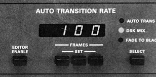
In this same group of controls, we would use the SELECT button to move the red indicator light to the AUTO TRANS position. The MIX button for the transition type and the BKGD button for the next transition are still pressed. (See Figure 9.17.) By pressing the AUTO TRANS button, we achieve a perfect two-second dissolve from camera 1 to camera 2. The fader bar is not moved, although it can be used to override the automatic dissolve at any time.
For an instantaneous cut between cameras 1 and 2, we would only have had to press the CUT button (next to the AUTO TRANS button) instead of the AUTO TRANS button.
Execution of the Wipe Transition
Once you understand the basics of the dissolve transition, accomplishing a patterned wipe is easy. First, we push the WIPE button for transition type (next to the fader bar; see Figure 9.17), canceling the MIX transition button. On the pattern control section of the switcher (see Figure 9.19), the SELECT button (under the pattern, with a confirming red light) determines the basic shape of the wipe. Keep in mind that the new video from the preset camera will appear in the white area of the pattern shown on the button. With the center circle wipe (the fourth wipe from the left in the bottom row of patterns), the new picture will emerge on the screen as a circle in the middle of the picture; its image will be widened by the movement of the fader bar.
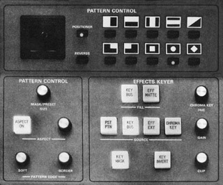
Selecting the REVERSE button causes the black area of the pattern to represent the new input. Other controls allow for changes in the position and shape of the circle or other selected design. You can also adjust the appearance of the edge of the wipe and the width of the border between the two video source pictures. The auto transition feature discussed previously may be used for the execution of wipes as well as for dissolves.
Keyed Special Effects with Two and Three Sources
Let’s say that we are going to use a key over camera 1 at the beginning of a program. To do this, we press black (“B”) on the program bus, camera 1 on the preset bank, and button 5 (for titles from the graphics generator) on the key bus (refer back to Figure 9.17). In this case, camera 1 is the preset background, and the graphics generator will be the key source. As with other effects, the fader arm can be in either the upper or the lower position to start.
The next two transition buttons in the effects transition area allow us to select the source bus or buses used in the next transition or effect. In this case, we press both the BKGD (background) and the KEY buttons, because, when we come up from black, we are going to fade to a key consisting of two images—the preset background from camera 1 and, keyed over it, the lettering originating from the graphics generator on the key bus 5 position.
In the effects keyer section (refer to Figure 9.19), we must press both KEY BUS buttons, because the key bus will be both the source and the fill of the effect. (If we were preparing a three-source key, we would punch up different sources for the source and for the fill.)
Once the selections are punched up on the preset background bank (camera 1) and on the key bus bank (the graphics generator), the preview monitor will display the key effect of those two sources. Because the difference in brightness between the lettering and the background is always a matter of delicate balance, a look at the preview monitor will now tell us just what adjustments must be made. The CLIP knob sets the brightness threshold for the key source video that allows the letters to “cut” the electronic hole, and the GAIN knob sets the sharpness of the key effect itself. After viewing the result of these adjustments, we are ready to fade up on the key effect by moving the fader bar to its opposite position. The key effect is brought up on the line, and we see the results on the program monitor.
Advanced Switcher Functions
Like most other components used in video production, some types of switchers can be very sophisticated, with additional capabilities and automated control. Still, the basic operating functions discussed in the first three sections of this chapter remain the same.
Digital Effects
Transitions such as dissolves and wipes and keying functions found on nearly all switchers are obviously quite useful to video production. However, these effects are also limited in the respect that they cannot make any significant changes to the switcher inputs. These effects merely arrange the inputs in different ways, revealing only part of them, perhaps, as in the case of an external key, or replacing one input with another by performing a gradual dissolve. No significant changes can be made to the inputs themselves.
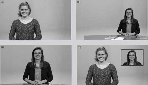
As an example of this limitation, consider the corner insert effect originally shown in Figure 9.10. The end result looks fine, but getting there requires some rather awkward camera work. The switcher’s box wipe effect cannot “squeeze” or move camera 2’s shot in any way—it can only reveal that portion of the shot where the box is positioned. Consequently, the shot on camera 2 must be framed so that the subject’s head is quite small and positioned in the upper right portion of the screen, as shown in Figure 9.20b. The operator of camera 2 must frame the shot so that the person’s head will be positioned exactly where the box cutout is.
By using DVE effects, however, we can “squeeze” and crop a normally framed shot into a corner of the screen. Thus, the operator of camera 2 could frame the shot normally, as shown in Figure 9.20c, and that shot can then be compressed and cropped by the DVE to create the effect shown in Figure 9.20d. This makes it easier to cut from the shot on camera 2 to the effect shown in Figure 9.20d. Or the switcher operator could set up a “live” DVE effect that would actually squeeze the full-frame shot from camera 2 into the corner in real time.
This is the essence of digital video effects. They allow the inputs of the switcher to be manipulated— stretched, bent, colored, flipped, spun around, and so on. Digital manipulation creates nearly limitless possibilities, not only for transitions but for creating other types of effects as well.
DVE Transitions
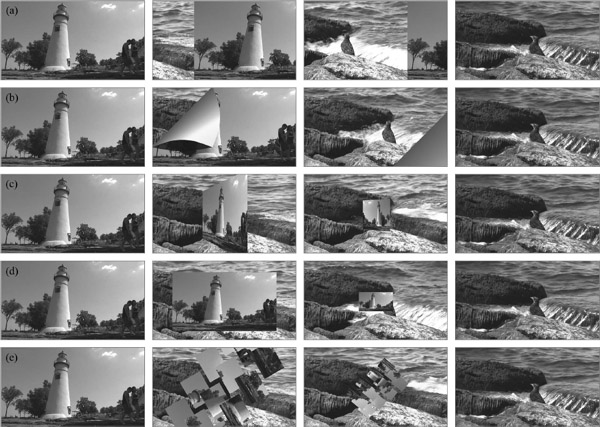
DVE functions can take transitions well beyond the capabilities of traditional dissolves and wipes. For example, in a push-off transition, the second picture seems to push the first picture off the screen, as shown in Figure 9.21a. Although this particular example shows the push moving left to right, the transition can move in any direction—vertical, horizontal, or at an angle. Another type of DVE transition “peels away” one picture to reveal another one, as shown in Figure 9.21b. Here, again, the example shown is but one of nearly limitless possibilities: The picture can peel away in any direction we want. In other DVE transitions, a picture can spin and appear to fly off the screen, as shown in Figure 9.21c, or zoom away, as shown in Figure 9.21d. In an even more sophisticated transition, the original picture breaks into cubes, which spin away to reveal the new picture, as shown in Figure 9.21e. Once again, the effects are open to nearly infinite adjustment to suit your particular goals.
The main thing to notice about these DVE transitions is that they are different from traditional wipes because they can actually change the video that is coming into the switcher. They create transitions by bending, stretching, flipping, and moving the video images. To make this point clearer, look at the two examples in Figure 9.22: (a) shows a left-to-right wipe effect (with no DVE), and (b) shows a DVE push from left to right. Notice how in (b) the original shot is being pushed off the screen; in (a) we are merely “covering” the original video from left to right with the new video.
Other DVE Effects
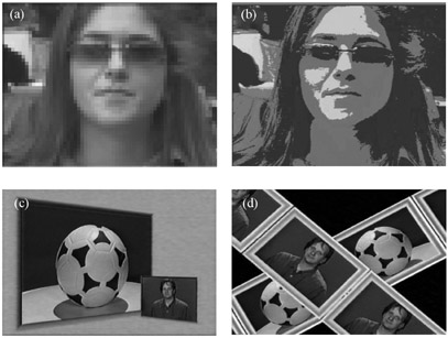
DVE functions also allow us to change the way video looks without actually performing a transition. For example, Figure 9.23a shows a mosaic effect, where the picture is given a tiled look. You may have seen this effect on television, used to obscure the face of someone who does not wish to be identified. Posterization, shown in Figure 9.23b, can be used to create a cartoon-like effect, reducing the number of colors in the picture and creating greater levels of contrast.
One of the digital switcher effects most often seen is continuous image compression, which enables the switcher operator to compress the full-frame picture down to the size of a tiny circle, square, or other shape (at any speed, to any size) and—with a joystick or mouse—to place the shrunken image anywhere on the screen. Image expansion allows the operator to take any segment of the video frame and enlarge it. Another effect is image stretching, where any portion of the picture can be expanded or compressed in any direction; ratios can be altered, and graphics can be shaped to fit the picture. This can be used to change the perspective of the picture, as shown in Figure 9.23c.
Digital video effects also allow us to combine several different inputs into a single picture, such as in a cube effect where each side of the cube is a different video input. The cube can even be made to spin, change sizes, or bounce off the screen if we wish. Similarly, we can create different types of layering effects, where various video inputs are placed over the top of one another, as shown in Figure 9.23d.
Increasingly, digital video effects are built into production switchers, especially high-end ones. DVE units are also available as separate pieces, which are normally designed to integrate closely with the switcher unit. As with any advanced technology, it is important not to let the “bells and whistles” of the equipment overshadow the actual content of your program. Just because you can perform more than 100 different digital transitions with your DVE unit, for example, doesn’t mean you should. All effects should be used judiciously and should enhance and never overshadow the content of the production.
Advanced Controls
High-end switchers can even be set up to control other studio equipment. For example, some switchers have the ability not only to take the video output from a server but also to play the clip. Similarly, switchers can control external DVE units by triggering when and how the DVE effect is executed, and they also can manipulate graphics generators and other graphics equipment. If the studio uses robotic cameras (as discussed in Chapters 2 and 5), some switchers are able to execute preprogrammed camera moves as well. Ross Video’s OverDrive system allows a single person to control nearly all the jobs in a live studio production environment: video switcher, audio control, graphics, robotic cameras, and lighting (see Figure 9.24).
Advanced switchers also allow the user to automate complex switching functions and switcher setups, saving the settings to computer disk and then recalling them. In this way, an operator can program complex switching functions and then have them execute with the touch of a single button. With proper planning, this allows very sophisticated switching operations to be performed in real time during a live broadcast with little chance of error.
The Director and the Technical Director
In most production situations, the technical director will operate the video switcher in addition to performing other duties as described in Chapter 2. Being a successful technical director requires understanding the technique of operating the switcher, the discipline of following direction, and the ability to focus on multiple tasks simultaneously. A well-prepared and disciplined technical director who has established a rapport with the director can go a long way toward making any video production successful.


Of course, the director has responsibilities in this relationship as well. As discussed in Chapter 4, the director’s commands of preparation are just as important as commands of execution. This is especially critical when giving commands to the technical director. Transitions and effects require switcher operation time. A straight take (cut) is ready instantly, but a dissolve to a chroma key effect requires a number of operations to be performed in a precise order. Thus, the director’s preparation commands must allow for sufficient lead time. Such commands, given over the intercom system, also allow camera, video playback, and graphics operators time for their own preparations.
One helpful rule is that the command of preparation for any straight take is “ready.” The preparation for any dissolve, super, fade, or special transition or effect that involves getting something set or prepared on another bus uses the command “prepare.” (Some directors prefer to use the command “set up.”) Although some directors use the term “stand by” as a preparation for both takes and dissolves, this can be confusing to the crew. The use of correct terminology lets the technical director know whether simply to get ready to push a button on the same bus or to set up a more complicated action. The command sequence for a direct take from camera 1 to camera 2 is stated by the director as follows:
- Preparation: “Ready camera 2” (or simply “Ready 2”).
- Execution: “Take 2.”
The word ready lets the technical director know only to place a finger on the camera 2 button on the program bus.
No matter how rushed the director may be or how fast-paced the program, the director should never skimp on commands of preparation. If occasionally the director does not have time to give full commands, some abbreviation could be used:
- Preparation: “Ready 2.”
- Execution: “Take it” (or simply “Take”).
If time is so short that even this much preparation is impossible (for example, shooting a game show, a fast-paced panel discussion, or a football game), the command of preparation still must be given priority:
- Preparation: “Two.”
- Execution: “Take.”
For a dissolve, the technical director will need to be given time to prepare for a more complex series of actions. Here, the director is likely to use the command “prepare.” Thus, assuming you already have camera 1 on the program line, the correct commands for a dissolve would be:
- Preparation: “Prepare a dissolve to 2” (or “Prepare 2” or “Set up 2”).
- Execution: “Dissolve to 2.”
For a super, the actions are the same, so the commands are much the same:
- Preparation: “Prepare to super 2 over 1” (or “Set up 2”—implying that camera 1 stays on the air).
- Execution: “Super camera 2 over 1” (or just “Super 2”).
We depart slightly from the basic pattern when two cameras are to be taken together in a super, key, or DVE effect. While these effects may involve a movement of the control levers and other switcher components to set them up, the movement is not one of program execution. The command of execution is “take”—calling only for the technical director to press the line mix output button or take bar. For this reason, the voice procedure in the case of a two-camera DVE effect should be as follows:
- Preparation: “Ready to take 2 and 3 in effect.”
- Execution: “Take effect” (or “Take 2 and 3”).
The repetition of camera numbers in the command is optional, but it does reinforce the intent of the command.
Much of the discipline necessary for keeping a program under control comes from this pattern of preparation followed by execution. The technical director must be able to depend on this sequence. The pattern will be broken when the director calls for a complicated effect that must be set up in advance. A complicated effect, for example, might need to be preset several shots before its use. In this situation, after the preparation command, which should acknowledge the time delay in execution, there may be several intervening commands. Then a new preparation command is issued before the execution command for the key. The first command of preparation must be given far enough in advance that the technical director has a chance to do the preset at a time most convenient during the ongoing program. The director should keep an eye on the preview monitor to see when the effect is ready. The commands might be as follows:
- Advance preparation: “We’re about to wrap, so preview your effect of camera 2 and full screen on the CG.”
- Ongoing shots in the program continue: “Ready 1,” “Take 1,” etc.
- Immediate preparation: “Now set up a dissolve to the effect of camera 2 and full screen.”
- Execution of the key: “Dissolve to the effect.”
Similarly, a command to preview and adjust—say, a corner wipe or an insert—in the coverage of a live event may be given well in advance of its eventual use on the air. There may be several intervening ad-libbed shots. This can be thought of as a non-time-specific command. For example:
- Advance preparation: “Preview a top-left corner insert, camera 3, of runner off first base, within camera 2.”
- Intervening shots ad-libbed: “Ready 4,” “Take 4,” etc.
- Adjustment of preparation: “Tighten the framing on camera 3 insert.”
- Intervening shots ad-libbed: “Ready 1,” “Take 1,” etc.
- Immediate preparation: “OK. Now, ready to take corner insert.”
- Execution of the effect: “Take effect.”
One final note: Fades to and from black are handled in a manner very similar to the dissolve. Because a sync black picture has such a definite connotation of separation or conclusion, many directors reserve the term “fade” for use as a command only to dissolve to or from black. This serves as a safeguard to protect against any inadvertent dissolve to full-screen black.
As switchers have become more complex, the numerous visual options available to the director have placed many demands upon the technical director. The director should use the clearest command language, and this command language should be based upon an operational understanding of what is involved in achieving execution of those commands. Beyond common courtesy, these good habits are practical. Ill-timed and poorly stated commands simply cannot be executed within the time frame that the director likely has in mind. Such a disparity can have serious side-effects, especially with live programming.
Focus Points
After reading this chapter, you should know . . .
- The basic configuration and design concepts of switchers.
- The types of buses found on switchers.
- The functions of various buses found on switchers.
- The basic operating concepts of a typical switcher, including performing cuts, dissolves, wipes, and other effects.
- Advanced functions of switchers, including digital effects and the control of external equipment.
- Commands given by the director to the technical director operating the switcher.
Review
- Evaluate the switcher in your school’s studio or in a local studio. Is it a special effects-generating switcher? Does it have a downstream keyer? How many inputs does it have? What kinds of effects can it perform?
- Why has the key replaced the superimposition in most video production situations? Can you think of a program in which you’ve seen a superimposition?
- How does the use of buses on switchers help simplify operation? Can you think of a more logical way to lay out a switcher?
- Explain the difference between a split-screen effect created on a non-DVE switcher and a similar effect achieved using a special effects-generating switcher. Do you think a viewer at home would notice the difference?
On Set
- Draw a schematic block diagram of your school’s switcher, similar to the example in Figure 9.1, showing the flow of video signals to and from the switcher. Include studio cameras, computer graphics units, tape units, servers, monitors, and similar equipment.
- Make a drawing of your school’s switcher, similar to the example in Figure 9.13. Each source button, fader arm, control knob, and switch should be labeled with a description of its function.
- If you have access to a virtual switcher, analyze how its controls and operation mimic the standard switchers discussed in this chapter. How do you set up the basic effects discussed?
Notes
1On most switchers, a selected button does not stay depressed but simply lights up to show it is selected. So the way to tell which button is selected on a bus is not to look for a button that is physically pressed down but to look for the button that is lit up.
2Occasionally, the word matte is associated with the key process. The term was derived from the traditional film technique that used printed or matted inserts within the larger film frame.
3Ultimatte is a trademark of the Ultimatte Corporation.