
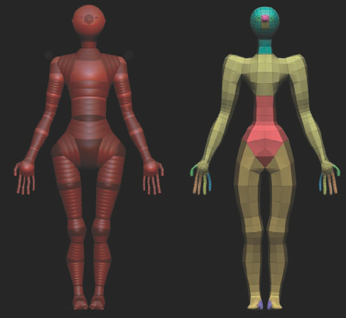
In this chapter, we'll look at ZBrush's polygon model–generating tool, ZSpheres. ZSpheres are powerful tools for quickly creating base meshes with speed and accuracy, much in the same way you might bend a wire armature upon which to sculpt. You don't have to painstakingly select and extrude polygon components like faces and edges—instead, you can use ZSpheres, which are based on a chain system of spheres where each link contains certain resolution information that allows you to create accurate topology when used correctly (Figure 6.1). ZSpheres have the added benefit that their topology is extremely well suited to the ZBrush topology masking tools as well as Transpose.
Given these benefits, it is only fair to mention a possible drawback of ZSphere modeling: you do not have the same control over edge placement as you do in traditional polygon modeling. This drawback is nullified, however, when you approach using ZSpheres as a method of building an armature and then use the topology tools to establish a proper layout when your sculpt is completed.
In this chapter, we'll build a biped body with full hands and feet entirely from ZSpheres. It is my hope that you will gain a level of understanding of ZSphere modeling that will allow you to quickly generate base meshes of any variety.
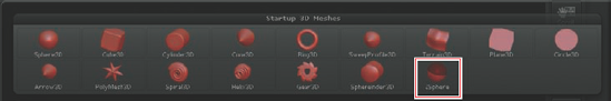
ZSpheres are accessed like any other tool in ZBrush: from the Tool menu. The ZSphere icon
When a ZSphere is drawn on the canvas, you must enter Edit mode as with any other ZTool. This establishes this first sphere as the root of your ZSphere chain. Any other spheres you draw will have to connect to this first sphere. As you work, you can move this sphere but you can never delete it—you can delete other ZSpheres at will, however. The chain created with a ZSphere will be converted to an adaptive skin to make a polygon mesh. An adaptive skin is a mesh generated by skinning a ZSphere chain based on the properties set for the spheres. We'll cover adaptive skins later in this chapter, but for now think of them as a polygon sock stretched over the ZSphere chain you created (Figure 6.3).
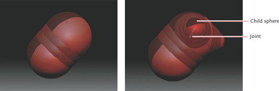
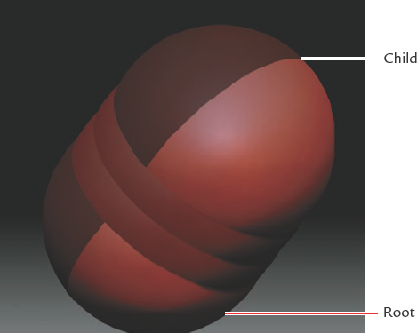
While in Edit mode you may tumble and navigate as with any other mesh in Edit mode by clicking outside the surface of the sphere on the background of the document window. If you try to click the surface of the sphere, you will notice that drawing on the ZSphere will draw another sphere on its surface, connecting it via a chain of concentric rings called joints (Figure 6.4). You will also notice that ZSpheres are two-toned with red and dark red. This is to help you spot twisting in the chain that will result in bad topology. We'll cover that topic later in this chapter, in the section "Moving, Scaling and Rotating ZSpheres and Chains."
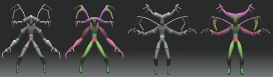
Figure 6.3. Adaptive skins behave like polygon socks stretched over the ZSphere chain you created. When you alter the chain, the sock stretches and adjusts to those changes.
Note
While drawing ZSphere chains, keep your Draw Size set to 1. This prevents you from accidentally selecting another ZSphere because it falls under your draw radius. It is also helpful to keep X Symmetry on, even when you're working on the center pillar of the body, because it assists in centering the ZSpheres (as you'll see shortly).
When you mouse over the ZSphere chain, notice that the ZSphere directly under the cursor is contained in a red circle. This visually cues you that this is the sphere you will be drawing a child to at that point. Let's quickly create a chain of ZSpheres to illustrate this process:
Select the ZSphere tool from the Tool menu and draw it on a clear canvas. Enter Edit mode by pressing the T hotkey. Shift-rotate-snap the sphere to an orthographic view so that the division between red and dark red is on the center line, as in Figure 6.5.
Turn on X Symmetry by pressing the X key and mouse over the ZSphere. When the two green dots become one, that means you are on the sphere's center line. Hold down Shift and click to create a new sphere the exact same size as the root.
In Figure 6.6 I have rotated off center so you can see the chain as it is drawn so far. There are two spheres; the lower one is the original root while the upper one is the child just created. At this stage, press the A key on the keyboard. This activates Preview Adaptive Skin. This allows you to see a preview of the polygon mesh the current ZSphere chain will generate. Notice that the root sphere creates a hole (Figure 6.7). This is because a root needs two children to form a closed mesh. For our demo this is not important, but it will become a concern when we move on to the biped. Press A again to return to ZSphere view.
Note
Double Sided was turned on in this image to help show the hole in the mesh. Double Sided is located under Tool → Display Properties (click the Double button

Back in ZSphere view mode, mouse over the child ZSphere you just drew. Drag on the surface to draw a new sphere. Since X Symmetry is on, ZBrush will create spheres on either side of the current sphere.
Exit Draw mode and enter Move mode by clicking the Move button at the top of the screen

Notice that the edges stretch between the two child spheres and their parent. To add a new edge loop in this area, simply click the space between them; ZBrush will automatically create a new sphere (Figure 6.9). To delete a ZSphere, simply Alt-click it and it will disappear. This operation is not possible for the root sphere as it cannot be deleted.
To scale a ZSphere, enter Scale mode by pressing the E hotkey or clicking the Scale button at the top of the screen


Notice that these transform operations (move, scale, and rotate) can be applied to a single sphere, but if you click the joint between them, the effect will be applied to the entire chain beneath that child. This works for moving, scaling, and rotating, but be careful when rotating ZSpheres as you can cause twisting in the mesh, as you'll see in the next section.
You've already seen that the transform operations can be applied to individual ZSpheres as well as entire chains. In Figure 6.11, I have rotated the whole arm by selecting Rotate and clicking in the joint between the shoulder and elbow. This action rotates the entire chain beneath the shoulder. Moving and scaling have the same effect. Remember that if you click the sphere it will affect just that sphere, but if you click the joint it will affect the entire chain beneath the bone.
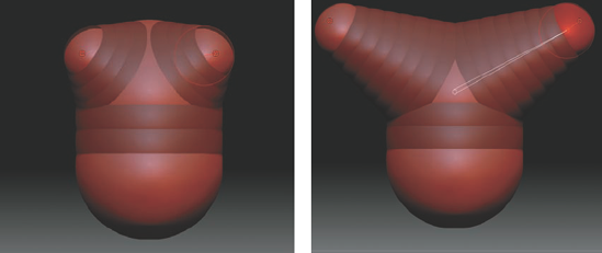
In Figure 6.12 I have rotated just the shoulder sphere and not the joint. It appears fine until you activate Preview Mesh and you can see the faces are twisted. To correct this problem, Alt-drag the sphere, and the individual spheres in the chain will rotate together, thus reorienting and correcting the twist. You may have to experiment with different directions and previews to get it right.
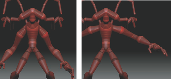

Figure 6.12. Rotating a sphere alone can create a twist in the mesh. To correct the rotations of ZSpheres, select Rotate and Alt-drag to reorient the chain.
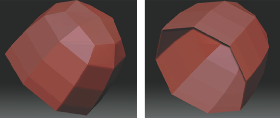
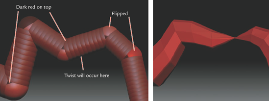
You can spot rotation errors in the sphere model by seeing if the ZSphere color codes are consistent. Remember that ZSpheres are red and dark red, so you can visually spot the orientation. In Figure 6.13, notice the orientations don't match, so the resulting mesh is twisted. When corrected, the mesh is fine.
Note
We are now ready to apply our knowledge of the theory behind ZSpheres and some of their basic controls to creating a biped character. Follow the steps in this section to build a humanoid armature and generate a polygon mesh as a base for sculpting. For a video of this process, see the DVD.
Don't be too concerned with generating a highly accurate silhouette or intricate edge loops at this stage. The point of this exercise is to create a general base on which to sculpt. With the ZBrush topology tools, you can generate any kind of base mesh you like after the sculpting is done.
Initialize ZBrush to clear any previous tools from the palette and the canvas. From the Tool menu select the ZSphere tool and draw the root sphere on the canvas. Press the T key to enter Edit mode. Open the main Transform menu and click the Activate Symmetry button, and then enable X and Y Symmetry (Figure 6.14). This will create four circles for your cursor. When all four become one, you know you are dead center on the root sphere. Shift-click to create the first child. If you see only two dots, that means you are looking at the side, so rotate to view the top of the sphere.
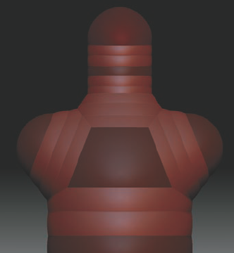
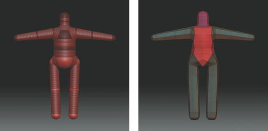
Rotate to the other side of the root sphere and repeat the process of creating a child. The resulting chain should look like Figure 6.15. Notice how the orientation of the ZSpheres flips on either side of the center root sphere. This is normal. Press the A key to turn on Preview Adaptive Skin. Your skin should look like a capsule, as in Figure 6.16.
This "capsule" will form the torso of your biped. Now you need to add arms and legs. Rotate to a side view and turn off Y Symmetry; be sure to keep X symmetry on. Draw a ZSphere at the shoulder by click-dragging on the side of the top sphere. This will create a child linked to the top, as shown in Figure 6.17. Repeat this process on the bottom sphere to create the hip spheres. Remember that your cursor will turn green when you reach the center line of a ZSphere. Try to draw new spheres when the cursor is green to get the best result from the mesh.
It's time to add a neck and head. Rotate to the top view and draw a new ZSphere between the shoulder spheres. Shift-click twice to make a chain of three spheres the same size (Figure 6.18). This process creates a simple head mesh. For a more advanced technique with eye and mouth edge loops as well as ear geometry, see the section "Adding Edge Loops to the Head" later in this chapter.
To add the arms, draw a ZSphere child from the shoulder ZSphere. Switch to Move mode (press the W key) and pull the sphere out from the sides. This sphere will be the wrist joint. Repeat the process for the legs (Figure 6.19).
You now have a very rough block of the figure. Let's now insert ZSpheres for the joints at the elbows and knees to further refine the gesture and proportion. Make sure you are in Draw mode by pressing the Q key or clicking the Draw button at the top of the screen

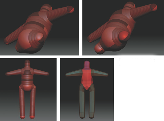
Switch to Move mode and begin to adjust the gesture of the figure. Look for the natural bend in the elbows and knees. At this stage, you can also lengthen the torso and pull the neck forward (Figure 6.21). Scale the spheres of the head up by scaling the neck bone. You can add a sphere in the abdomen and scale it down as well as rotate the torso back slightly to add a bend to the spine. The ZSphere chain so far is pictured in Figure 6.21.
At this stage, you could move on to hands or add a few more ZSpheres to increase resolution and reinforce the curves of the figure. Usually I prefer to keep ZSphere chains as simple as possible, but adding these next few spheres to establish the rhythms of the body can be helpful. If you choose to skip these spheres, that's fine—the same curves can be introduced in the sculpting phase.
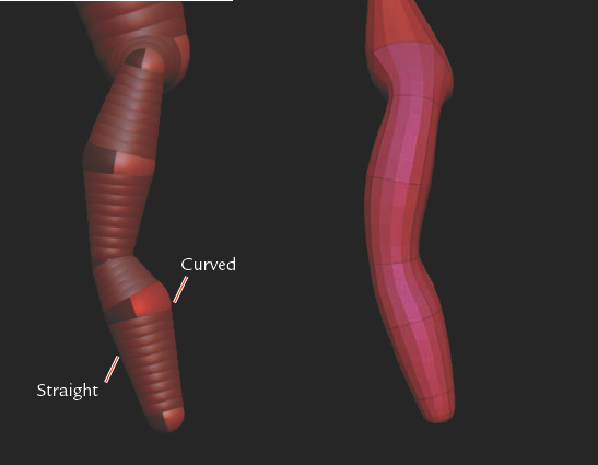
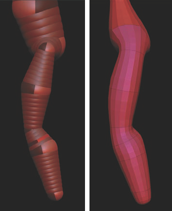
Add a new ZSphere between the knee and hip spheres. Scale it up slightly and move it forward to give the thigh its characteristic curve.
Let's use the same approach for adding curvature to the back of the calf. Move the sphere back after scaling so the front of the shin is straight while the back is curved (Figure 6.22). You can improve the transition between the calf and knee by making it a sharper turn. To do so, add another ZSphere between the knee sphere and the calf sphere (Figure 6.23).
Add a sphere between the shoulders and elbow to serve as the mass of the upper arm (Figure 6.24). Also add a sphere on the upper arm close to the elbow to shape the join and make the arm appear less like a curved tube (Figure 6.25).
Add a sphere just below the elbow; this will serve as the forearm mass. The elbow transition can be further sharpened by adding another sphere between the forearm sphere just created and the elbow sphere (Figure 6.26).


That completes the body for the figure. Your ZSphere chain and mesh should look like the one shown in Figure 6.27.
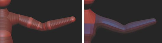
Figure 6.26. An extra ZSphere below the elbow, and another between the elbow and forearm joint, will further define the transition between the upper and lower arm.

Next, let's add hands to our ZSphere figure. There are several approaches to making hands, some more complex than others. More involved approaches can offer animation-friendly topology right out of the adaptive skin, while less complex procedures offer a hand mesh that is ideal for sculpting with minimal effort. With the addition of topology tools in ZBrush 3, I find it is best to work with a simple ZSphere layout and build the animation mesh at a later time. This allows you to get to the sculpting phase faster, and the chances are a ZSphere mesh (much like any starting base mesh) will need to be tweaked for an animation pipeline. A simple process for making hands and feet follows.
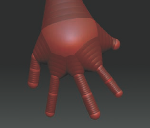
Begin by drawing a hand sphere at the end of the arm chain. This new sphere will be the palm and all 5 fingers will be drawn from this sphere. Draw 5 spheres on this hand sphere. (Figure 6.28a)
Move the thumb sphere down slightly. This will allow the 4 finger spheres more space in which to flow into the hand and also creates a more realistic placement for the fingers (Figure 6.28b)
Press A to preview the skin. You will see the 4 fingers flow straight back into the hand and the thumb flows into the side of the hand and palm. You will want to draw new spheres at the tips of each finger now and pull them out with Move to create length. It is also a good idea to insert spheres in the middle of each finger to increase their resolution. Before you preview the skin make sure the Ires setting is 3 under Tool → Adaptive Skin. (Figure 6.28c)


This same process applies to feet as well. The key is keeping the Irs setting to 3 so the parent sphere is of suitable resolution to support the fingers or toes. Please visit www.scottspencer.com for bonus material on advanced ZSphere hand approaches as well as a script for manipulating ZSpheres by ZBrushCentral user TVEyes. I recommend looking at this material if you want to pursue more advanced ZSphere applications. The workflow I will show you now is ideal for creating a fast and efficient base hand mesh.
Please visit http://www.scottspencer.com for bonus material on advanced ZSphere hand approaches as well as a script for manipulating ZSpheres by ZBrushCentral user TVEyes. I recommend looking at this material if you want to pursue more advanced ZSphere applications. The workflow I will show you now is ideal for creating a fast and efficient base hand mesh.
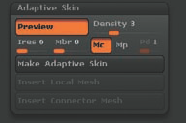
Throughout this chapter we have been using the A key to preview our mesh. What this is doing is creating an adaptive skin based on the ZSphere chain. As you recall, adaptive skins are like polygon socks stretched over the ZSpheres. You can control how the sock stretches as well as how dense it is by altering the adaptive skin controls. These are found under the Tool → Adaptive Skin menu.
Here you will find several sliders. We'll go into some more detail on those you will use often. The Preview button will show a preview of the adaptive skin. This is what we have been displaying with the A hotkey. The Density slider
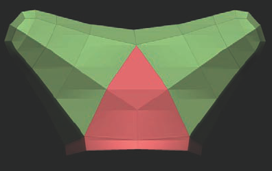
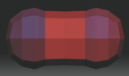
Minimal Skin to Child allows the child sphere to determine the connection points of the mesh but not to add new geometry. This accounts for the V-shaped transition seen in the crotch in Figure 6.30. Minimal Skin to Parent allows the parent sphere to determine the connecting points. Figure 6.31 illustrates how turning on Mp can change topology as well as curvature in the wrist.
The Mbr slider controls membrane curvature. This is the curvature of the mesh between ZSphere intersections. When set to 0, this slider has no effect. As you raise the value, the transitions between spheres will change.
Finally, there is the Make Adaptive Skin button

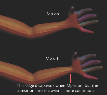
Figure 6.31. Minimal Skin to Parent can create a smoother transition into the wrist while removing the influence of the parent ZSphere on the topology.
Table 6.1. Options in the Adaptive Skin Subpalette
By adding a few more spheres to the head, we can give our model loops for the eyes and mouth as well as geometry to carry the nose. This ZSphere head is designed to allow for optimal edge loops for the eyes, nose, mouth, and ears.
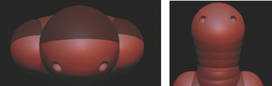
Let's begin with the neck sphere already drawn on the torso. Draw the head ZSphere on the neck and move it up away from the body (Figure 6.31). Press the A key to preview this head mesh.

With X Symmetry on, draw two small ZSpheres for the eyes. Switch to Move mode and move them back into the head until they become concave holes instead of spheres (Figure 6.32).
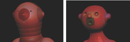
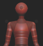
Draw a mouth sphere. Again, move it into the head to create a hole. Likewise, create spheres for the nose and ears (Figure 6.33). Press A to preview the mesh. Because we have Ires set to 3, any sphere with more than three children will automatically become a higher-resolution mesh, creating the loops for the eyes and mouth as well as extra geometry for the ears and nose. While this mesh may look extremely basic, almost toonish, now it is absolutely effective as a base for sculpting any number of realistic characters.
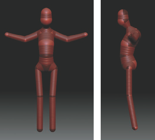
That concludes the process of creating the ZSphere armature. You have now a solid base mesh you can sculpt on without ever leaving ZBrush. We'll sculpt in the major muscle forms and secondary forms of the face using the standard ZBrush sculpting tools, much as we did on the sphere in Chapter 2. ZSpheres work best as a quick and efficient mesh-generation tool. Part of the strength of ZSpheres is the ease with which you can re-pose and change proportions by just moving and rotating the chain. Figure 6.34 shows the figure re-posed and reproportioned.
Extreme changes to scale and placement of these spheres can yield a completely different type of character (Figure 6.36). It is also a simple matter to add in various parts. For instance, Figure 6.37 shows the same figure with centaur legs and bat wings.
Remember to press MakeAdaptiveSkin and select the new ZTool when you are finished editing the ZSpheres. A common error is to try and work on the adaptive skin preview mesh instead of saving a proper adaptive skin Ztool.
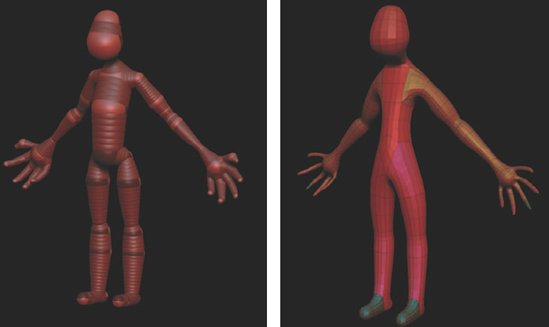

Figure 6.36. The same ZSphere chain rescaled and re-posed to create a more hulking monster type of character. No new spheres were added here—I only made changes to the existing spheres.
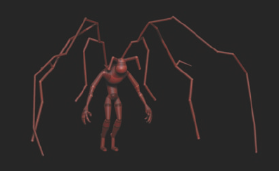
Figure 6.37. New appendages like wings can be added easily while existing limbs can be quickly reconfigured.
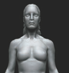
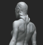
This concludes our look at building ZSphere bases for our characters. ZSpheres are a quick and powerful mesh-generation tool that can help speed up your sculpting workflow by freeing you from many of the more tedious base modeling tasks. The armatures built with ZSpheres are perfectly suitable for any kind of character or prop creation. Figure 6.37 shows a female figure sculpted from a ZSphere base by Ryan Kingslein. I encourage you to experiment with ZSphere modeling. With just a little practice, using the tools will become second nature and you will be generating base models in no time.
