After sculpting and painting your character in ZBrush, you may want to transfer your work into another application such as Maya or 3ds Max for animation and rendering. Your final product may be for film, video games, or even print. By giving you a method of rendering your ZBrush work in other applications, Pixologic has opened the door for ZBrush to become a staple in professional entertainment industry pipelines.

Although most applications cannot render millions of polygons, and at this time no application can animate a mesh with such a high polygon count, you can still use your ZBrush asset in a visual effects or game pipeline. By using difference mapping, you can re-create your high-polygon digital sculpture in a suitable renderer.
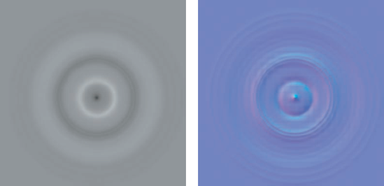
Before we proceed, it is important to understand the concept of difference maps and how they function. In this context, the term difference mapping refers to texture maps generated by calculating the difference between two surfaces, usually a high-resolution polygon mesh and a low-polygon counterpart placed together in world space so the program can find the corresponding point on the high-res mesh that matches the same point on the low-res mesh. ZBrush will calculate the differences between a high-res mesh and a low-res surface and produce a value appropriate for the kind of map being generated. The resulting map can be used in a third-party renderer to re-create the look of the highly detailed ZBrush model. ZBrush can create two kinds of difference maps: displacement maps and normal maps (Figure 9.1) In this chapter, we'll focus on displacement mapping.
Displacement maps create high-resolution details by physically displacing the geometry at render time. The model is sliced into millions of triangles by the renderer in a process called tessellation. The surface is then pushed in or out based on a grayscale value in the displacement map. Some renderers perform subpixel displacement, which is a re-tessellation of the surface into micropolygons or microtriangles to support even finer details. The important thing to understand is that displacement mapping requires that the geometry be heavily tessellated at render time.
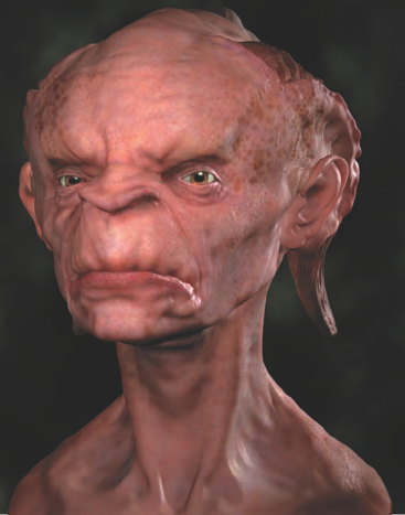
Because these maps create actual geometry, they are heavy on processing power and can involve long render times. They also offer superior results compared with any of the other mapping types since the rendered mesh is extremely dense and carries all the details of the surface and silhouette. This is in contrast to normal mapping, which only creates the look of a highly detailed surface without changing the underlying geometry or polygon count. See Figure 9.2 for an example of normal mapping versus displacement.
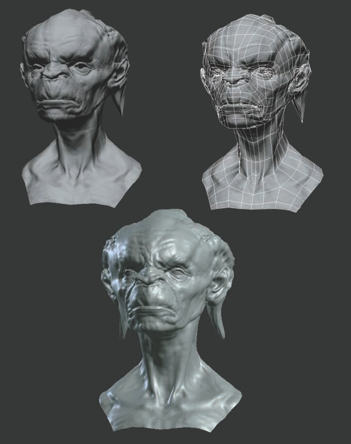
Figure 9.2. Two renders of the same character. On the normal mapping example at the top, notice how the internal forms appear highly detailed while the silhouettes still display polygon faceting. The image in the upper right shows the polygon mesh itself. The displaced render at the bottom contains all the fine details on the surface as well as a displaced profile with no faceting.
ZBrush also enables you to create bump maps by using the bump viewer material or by generating a displacement map for use as a bump map. In technical terms, bump maps and displacement maps are identical—it is the renderer that reads and displays them differently. Both are grayscale maps with white values representing height and dark areas representing depth. In application, however, bump maps differ from displacement maps in that they do not change the overall silhouette of the surface. Bump maps give the impression of surface detail where there is none by perturbing the surface normal of the mapped faces. Because bump maps don't require heavy subdivision at render time, they render much faster than displacement maps but do not provide high-quality results since the profiles are not altered. Bump maps can be extremely successful when combined with displacement maps. See the section "Applying Bump Maps in Maya" later in this chapter for more information.
Normal maps are similar to bump maps in that they do not alter the profiles but they offer more realistic shading on the surface details. While bump maps perturb the surface normal, a normal map replaces it entirely with an RGB value. This vector value can represent the X Y Z coordinates of the surface normal of the high-res mesh and allows for highly realistic detailed surfaces but won't affect the low-poly faceting of the shape's edges. Normal maps are used heavily in video game applications.
In this section, we'll discuss how to export your mesh from ZBrush as an OBJ file ready to import into Maya. We'll look at various options for UV mapping as well as methods of replacing the UVs on the ZTool before exporting geometry and displacement maps. For rendering, we'll be using the mental ray render plug-in. mental ray comes with Maya and offers extremely powerful rendering options for displacement mapping:
Begin by exporting the lowest subdivision level of your ZTool from ZBrush as an OBJ file. When exporting an OBJ from your ZTool, be sure you are at the lowest subdivision level or the level you want to generate your displacement map from.
You must verify some settings before exporting geometry from ZBrush. Under the Preferences menu, open the ImportExport submenu and turn off the iFlipY, iFlipZ, eFlipY, and eFlipZ buttons. These will flip the model's orientation when exporting from ZBrush. Turning off these options keeps the model's orientation and placement consistent.
To export the level 1 mesh, select Tool → Export and turn on Mrg and turn off Grp. The MRrg button will merge the UV points. If you left this button off, each UV would be an unmerged point and could cause problems later during rendering. Leave the Scale slider at The slider will rescale the object on export, which can be problematic when you're trying to render accurate displacements.
When generating displacement maps in ZBrush, it is important to be sure the UVs do not overlap at all. Overlapping UVs (which are easy to miss) will cause unexpected crashes when you are extracting your displacement map. You can avoid this problem entirely by using ZBrush AUV tiles or other automatic options for your mapping. This approach will remove any possibility of overlapping UVs, but as you will see, having UVs laid out in Maya instead will open up several workflow possibilities not otherwise available. AUV tiles are not human readable, which makes editing color maps in Photoshop nearly impossible.
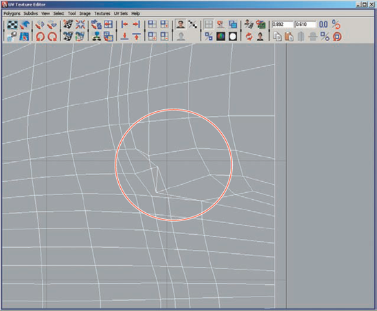
Figure 9.3 is an example of overlapping UVs in the toes of a model. This problem must be corrected before the displacement map can be extracted. Otherwise, this small overlap could cause a crash. If at any point you crash while generating a displacement map, chances are extremely good that you have a minor overlapping UV.
Note that unless you are painting color maps with UV projection techniques, ZBrush is not concerned with UV coordinates This leaves you free to model and paint in ZBrush and then lay out UVs later or change your UV layout without losing all the work you applied to your model. ZBrush also offers a tool to check for overlapping UVs under the Tools palette: select Tools → Texture and click the UV Check button (Figure 9.4). Clicking this button will highlight in red on your model any overlapping UVs, so you know where to look for errors back in Maya. When performing an inspection like this in ZBrush, be sure to rotate your models to view all surfaces.

It is also possible at this phase to place your UVs outside the 0 to 1 texture space. This will allow you to use polygroups to organize your mesh in ZBrush for easy masking and hiding as well as enable you to maximize texture space and extract maps for each body part instead of a single map for the entire model.
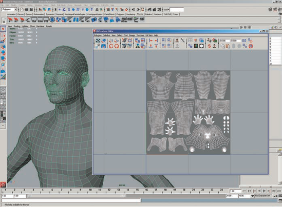
Figure 9.5 shows an acceptable UV layout for a model. The UV shells are all in the dark gray square, which represents the 0 to 1 range. This will generate a single map in ZBrush that applies to the entire mesh. The multiregion layout in Figure 9.6 will allow you to interactively hide parts of the mesh using the UV Groups option (as discussed in Chapter 3). This layout will also enable you to generate multiple displacement maps for your mesh so that you can spread the body parts out across multiple maps, thus giving more texture space to the displacements. For example, the head, torso, legs, and tail may each have a displacement map at 4096x4096 resolution as opposed to spreading the detail for the entire body over one 4096 map.
If for any reason you need to change the UV coordinates of the model before generating maps, this is no problem. The process of transferring a model from ZBrush to Maya and back to ZBrush seamlessly is as follows.
You can move the OBJ file between applications as long as the vertex order remains unchanged. Vertex order is changed by cutting new faces, deleting faces, or reordering on import. Use the following process any time you transfer your model between Maya and ZBrush:
In ZBrush, select Tool → Geometry and set SDiv to Export by choosing Tool → Export. Be sure the iFlip and eFlip options are off and Mrg is on.
Save the mesh as an OBJ file.
In Maya, choose File → Import

Make any positional or UV changes you want and export the OBJ again. This means you can move faces, repose characters, or change UVs, but you can't change topology.
In ZBrush at subdivision level 1, choose Tool → Import and select the new OBJ file. The UVs will automatically update to the ones in your new OBJ file. You can verify the updated UVs by using the Morph UV option in ZMapper, as described in Chapter 5.
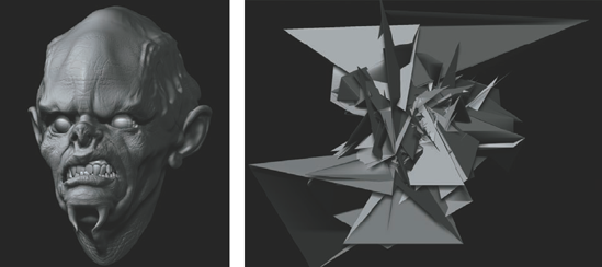
If you import a model into ZBrush and the vertex order has changes, it may appear to import fine. The problem manifests when you try to step up subdivision levels. The mesh will explode, as shown in Figure 9.8.
ZBrush is capable of creating 16-bit and 32-bit maps in single-channel grayscale or three-channel RGB. You also have the option to break displacements apart into multiple 8-bit maps if the renderer of your choice does not support 16-bit. In this section, we'll discuss how to create the two most useful kinds of displacement maps, 16-bit and 32-bit. Regardless of the type of map you generate, it is important to be aware of the shape of the base mesh from which you generate compared to the mesh on which you will render it.
ZBrush is a multiresolution editing tool, meaning that changes you make at the higher subdivision levels will telegraph back down to the lowest subdivision level, somewhat changing the shape of the original mesh. In some cases, you may want to access your original mesh shape again; for example, you may want to generate a displacement map against the shape built in Maya, as opposed to the somewhat different level 1 shape that will result after sculpting in ZBrush. To do this, follow these instructions:
To ensure that you can return to the original Maya shape in ZBrush after sculpting, store a morph target before you begin sculpting: simply press Tool → Morph Target → StoreMT before you start modifying your model. After sculpting, you can use Tool → Morph Target → StoreMT to switch back to the original shape. An alternative way of doing this, which does not require storing a morph target, is simply to reload the Maya model after sculpting as the level 1 mesh of your sculpted model. This approach will work as long as vertex ordering has not changed (which should be the case as long as you have not added or removed points or edges). The morph target method is generally preferred because some programs can, on occasion, alter the order in which they write model vertices on export, even when the model has not changed at all.
It is also important to note that using tools like the Transform → Nudge and Transform → Pinch Brush will make changes to the mesh that will not necessarily translate well into the maps created when setting a DPSubPix value as opposed to those generated using Adaptive mode (these settings will be discussed in detail later). This explains why in many cases when using these tools on your mesh, you'll find it beneficial to use the slightly shape-modified level 1 mesh for your base in Maya as opposed to the original morph target. In any case, always apply your displacement map to the geometry you generated it from in ZBrush. If you use the original morph target be sure to export this mesh to Maya for displacement.
If you find that areas that have been pinched together are creating undesirable effects in the render, try using the Reproject Higher Subdiv button under Tool → Geometry. Reproject Higher Subdiv will allow you to relax the underlying edges while maintaining the sharp edges. This tool is discussed in depth in Chapter 2.
Note
If your base mesh is already rigged and cannot be changed in Maya, export the ZBrush level 1 mesh as an OBJ import into your Maya scene, and add it as a parallel blend shape to reshape the original mesh to the level 1 form exported from ZBrush.
If you plan on using a displacement map for detail transfer, as in Chapter 3, you must use a 16-bit map. For all other rendering, I recommend using 32-bit, which is described in the next section. There are situations where a 16-bit map may be needed in a pipeline. These cases include pipelines that don't support 32 bit (these are rare these days) and the increased overhead of multiple 32-bit maps in a single render. For your own personal renders, I recommend using 32 bit as much as possible; the results will always be far superior to 16-bit displacement.
Generating a 16-bit map in ZBrush is simple. To do so, follow these steps:
Step down to your lowest subdivision level in ZBrush. Make sure the mesh has UVs that do not overlap.
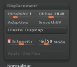
Select Tool → Displacement and set MapRes to 2048 (this value can be higher or lower, but multiples of 2 are recommended, as in 1024, 2048, or 4096). Set your DPSubPix to 1 and click Create DispMap (Figure 9.9).
Note
The difference between DPSubPix and Adaptive mode is in how the displacement map is generated. DPSubPix mode is a global subdivision value. With DPSubPix set to 2, for instance, when ZBrush generates the map it subdivides the entire mesh two more times in memory, thus allowing you to create a crisper, higher-quality map. Adaptive, on the other hand, is a feature-based displacement mode. This means that as the map generates, ZBrush will subdivide only those areas of high detail. For this reason, adaptive mode is sometimes faster than DpSubPix. Both map types have their benefits.
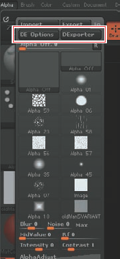
The map will generate and appear in the Alpha palette when it is complete (Figure 9.10).
Before this map can be rendered in ZBrush, you will need to process it using the DExporter options in ZBrush. This map is a single-channel grayscale image while Maya requires a three-channel RGB image for displacement. You will also need to flip the map in the V direction since the texture space between ZBrush and Maya is different.
From the Alpha palette, select the newly created displacement map. Under the main Alpha menu, click the DE Options button (Figure 9.11). This will load the Displacement Exporter interface (Figure 9.12). This screen allows you to specify the file settings for the displacement map you want to export from ZBrush. For rendering in mental ray for Maya, select R16 and set the Status switch to On. Each of the boxes at the top of the DE Exporter screen represenst a selection of file type presets. R16 is the slot for RGB 16 bit. Enter the following settings:
Setting
Value
Channels
1
Bits
16 bit
Vertical Flip
Yes
Scale
A.D. Factor
Ch1 Range
Full Range
Ch2 Range
Full Range
Ch3 Range
Full Range
Ch 1 Res
Full
Ch 2 Res
Full
Ch 3 Res
Full
Click the Export Current button to export a RGB displacement map based on the settings you just entered. A file browser dialog will appear. Browse to the location you want to save the displacement map and click Save.


You have now generated a 16-bit map from your ZTool and prepared it for rendering in Maya. You can move ahead to "Setting Up Single 32-Bit Displacement Renders in Maya" or read the next section for details on generating a 32-bit floating-point map.
You can only export 32-bit floating-point maps using the Alpha Displacement Exporter menu found under ZPlugin → Multi Displacement They can be exported from ZBrush but not reimported, so if you plan on using a displacement map for detail transfer as in Chapter 3, you must use a 16-bit map. For all other rendering I recommend using 32 bit whenever possible.
Note
The 32-bit floating-point maps generated in ZBrush should not be edited in an external editor—doing so may alter the map in undesired ways.
You can access this plug-in from two places in the ZBrush interface: under the Alpha menu (Figure 9.11) and in ZPlugin → Multi Displacement 3 (Figure 9.13). Although it is possible to export 32-bit maps from the Alpha menu, we won't use this button to do so in our example. This is because if you generate your map using the facilities in Tool → Displacement and then export it from the Alpha → DExporter menu, you will get a 32-bit map without real-world scale.

Figure 9.13. The Displacement Exporter can also be accessed via the ZPlugin menu under Multi Displacement 3.
If you generate a map from this menu for an object imported into ZBrush, the map will not appear to render correctly in the outside application. The reason is that ZBrush scales your model to one ZBrush unit multiplied by your Unify Scale setting in your Preferences palette. When you export the geometry, it will return to the original scale as the imported model. Maps generated using the Tool → Displacement menu will be baked with the internal ZBrush scale. On the other hand, to generate a map with the original object scale baked in, we need to use the Multi Displacement 3 plug-in found under the ZPlugin menu.
Note
The importance of having real-world scale baked into a 32-bit map is to simplify the rendering process. Sixteen-bit maps record only that one point is higher than another point; 32-bit maps record the relative height of the highest point and depth of the lowest point in relation to the overall scale of the object. This means that your settings in Maya will remain consistent for all 32-bit displacement maps you render. At the same time, 16-bit maps require some rescaling of values to achieve proper renders.
The original function of Multi Displacement 3 is to generate multiple maps based on UV region, but if your UVs are all in 0 to 1 space, it will create a single map as you'd expect.
This method is also useful if you have set up UV regions outside 0 to Multi Displacement 3 will generate maps automatically based on each separate region. For example, a model with four UV shells in four separate regions will get four separate maps. Since the Alpha Gain is consistent between the maps, there will be no seams when these maps are applied to the mesh and rendered in Maya. This allows for higher-quality displacements since more texture space is allotted to each part instead of the whole character's displacement being contained in a single map.
Note
Suppose your base mesh is already rigged and cannot be changed in Maya but you want to displace the ZBrush level 1 mesh that has been slightly altered by sculpting. In this case, export the ZBrush level 1 mesh as an OBJ, import it into your Maya scene, and add it as a blend shape to reshape the original mesh to the level 1 form exported from ZBrush.
Multi Displacement 3 has several menu options:
- GetMeshInfo
Shows you how many UV regions are in the model. This corresponds to the number of maps that will be generated. A single UV region (UVs laid out in 0 to 1) will generate only one map and only one tile will be shown when you click this button.
- Create All
- Create Missing
Examines the export folder and generates maps that are missing.
- Udim
Specifies the number of regions in U (left to right); leave this set to 0.
- Initial File Index
Specifies the number assigned to the first map generated. Leave this set to 100The setting will increment as each file is generating, thus giving them unique names. The last digit will correspond to the UV region in which the shell lies, starting from left to right.
- MaxMapSize
Specifies your map resolution. Set this to 4096 or 2048. Lower numbers will be faster but result in lower quality.
- MapSizeAdjust
Set this to set to 0. This slider will automatically adjust the map resolution based on UV space. By setting it to 0 all maps are generated at the resolution you specified in MaxMapSize.
- DpSubPix
Governs the quality of the map generated. It specifies the number of times the mesh is "subdivided" as it generates. Set this to a value above 0: 1 subdivides once, 2 twice, and so on. Be aware that this will be memory intensive the higher it is set.
- Overpaint Border Thickness
You can leave this setting at 8. This setting creates an overpaint at the UV border and can help to avoid seam issues in some renderers.
- Export Options
Opens the Displacement Exporter dialog menu.
The Displacement Exporter allows you to export alphas from ZBrush as various kinds of displacement maps and even normal maps. Even though you can create normal maps with Multi Displacement 3, I recommend using ZMapper for the higher level of control it offers. Each option slot can be turned on independently and allows you to specify settings for each map type.
To create a 32-bit floating-point map with Multi Displacement 3, follow these steps:
Click the main ZPlugin menu and open Multi Displacement 3Set MaxMapSize to 2048 and MapSizeAdjust to 0. Also, set DpSubPix to 1.
Choose Export Options to open the Displacement Exporter window. Select the D32 option and set the 32-bit export options listed here:
Channels 3
Bits 32 Float
Vertical Flip Yes
Scale A.D. Factor
Smooth No
Seamless No
Channel 1 2 and 3 Range are all set to Full
Channel 1 2 and 3 Res are all set to Full
These are the ideal settings for a 32-bit floating-point-map to render in mental ray for Maya. Your Multi Displacement 3 Export options should look like Figure 9.1Click Close.
You may now generate your mesh based on SubD levelIf you decide to generate off a level higher than 1, be sure to export an OBJ file of that subdivision level to displace in Maya. Click the Create All button. A file browser will open. Select the folder in which you want to save the resulting displacement map. ZBrush will generate and then export the map based on the settings you specified.

It is important to remember that with the Displacement Exporter there is no reason to open your map in an external image-editing software and resave it. In many cases this will destroy the floating-point data and render the map useless.
Maya provides a nice utility called imf_info.exe in the Maya/bin directory. You can use this program at the command line to read detailed information about your displacement map.
imf_disp.exe is another utility that will display maps and offer information on them. This utility features a graphic interface.
Note
Your displacement maps will perform far better, faster, and with more stability in mental ray if you convert them to the mental ray native file format, .map. The difference is especially apparent with higher-resolution maps. Maya will process the render at a noticeable speed increase in many cases, and crashes are less common when working with larger map resolutions. Using the .map file format will also increase your speed at render time because .map files use mental ray's memory-caching features. Taking care with how mental ray handles memory will speed up renders and make for far better performance.
mental ray comes with another command-line utility called imf_copy, which will allow you to convert TIFF files to the .map format. To run this utility, open a command window in the folder where your TIFF files are located. Use the following command line to convert to .map format:
imf_copy –p originalfile.tif newfilename.map
Note
To open the command window on a Windows machine, choose Start → Run and type command.
Note
Perform this conversion on all displacement maps you plan to use. The maps will cache in memory and render faster and with fewer crashes. Included on the DVD is a Windows batch file to automate this conversion process. Simply drag and drop your TIFF files onto the convertfile.bat icon, and they will convert and save in the original location.
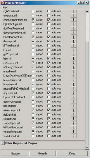
Whichever map type you decide to use, follow these steps to prepare your model to be displaced in Maya. Before we begin, you must load two plug-ins in Maya. The OBJ exporter is a plug-in that allows ZBrush to read the OBJ file format. The mental ray renderer is also a plug-in we'll load at this stage so it will be available when needed.
To load the mental ray plug-in, select Windows → Settings and Preferences → Plug-in Manager. This opens the Plug-in Manager window (Figure 9.14). The OBJ plug-in is called objExport.mll and the mental ray plug-in is called Mayatomr.mll. Click the Loaded check box next to each to load them now; you may also want to click Auto Load so they are available every time Maya starts.
Note
At the time of this writing, Autodesk has released Maya 2008. This new release has several changes to the core functionality of rendering, which can cause problems with displacement maps. This chapter addresses Maya 2008–specific settings in notes like this.
In this section, we'll import the level 1 mesh to Maya, set up displacement shaders, and start rendering. We'll use a single displacement map to represent the entire character. In the next section, we'll look at using multiple displacement maps for a single character.
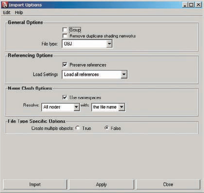
Import the level 1 OBJ into Maya. Make sure Make Multiple Objects is set to Off in the Import Options dialog box. With the mesh selected, press Ctrl+A to open the Attribute Editor. In the shape node, turn off Feature Displacement (Figure 9.15).
You now need to add a Subdivision Approximation to the mesh to tell mental ray how to subdivide at render time so there is enough geometry to support the displacement detail you need. To do this, use the mental ray Approximation Editor. Choose Window → Rendering Editors → mental ray → Approximation Editor (Figure 9.16). This control panel lets you specify how much you want to subdivide the mesh at render time. The higher the subdivision, the easier it is to pull fine details in your render.
Be sure that Show in Hypergraph is checked and click the Create button next to Subdivision Approx. The Edit button will now become active; click this to open the options in the Attribute Editor.
Change the Approx Method to Parametric. Set the N Subdivision setting to 4 and press Enter. This will be a good start, but this value can be increased as you render to find the best balance between surface-detail quality and render time. The N Subdivision setting controls the fineness of the surface tessellation at render time.


Now we'll create a shader for using a 32-bit floating-point map in Maya. If your initial OBJ file has all its UVs in the 0 to 1 range, or if it was mapped with AUV tiles inside ZBrush, you only have one displacement map from ZBrush, and you will only need to create one shader and apply it to your mesh. For rendering multiple maps, see the following section, "Setting Up Multimap 32-Bit Displacement Renders in Maya."
Open the Hypershade by choosing Window → Rendering Editors → Hypershade.
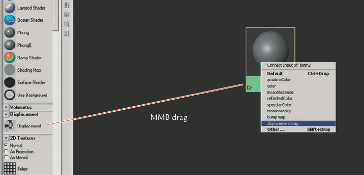
Create a Blinn material by dragging it to the workspace from the left window. I use a Blinn shader because it has a specular channel and this slight highlight helps spot finer details on the displaced surface.
MMB-drag a displacement node over the material. Select Displacement Map from the Connection Editor window that appears (Figure 9.17). Double-click the displacement node to open the attributes. You need to tell the shader it will use a file for displacement. Click the checker box to the right of the Displacement attribute. This will bring up the Create Render Node window. From this window, select File from to create a file node and connect it to the Displacement node.
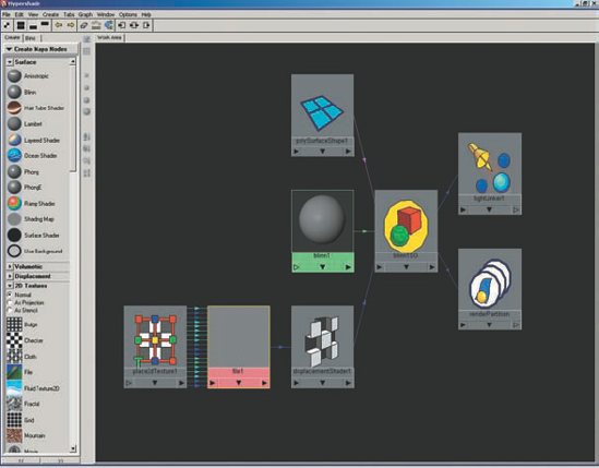
This creates a file node in which you can place your displacement map. You can graph your shader by selecting Blinn. Then in the Graph menu, select Input and Output Connections.
Your shader graph will now look like the one shown in Figure 9.18.
In the file node, you'll add the displacement map. The File Node options should open automatically in the Attribute Editor when you click the File button; if not, double-click the file node in the Hypershade. The File Node options will be visible now in the Attribute Editor. Click the folder next to the image name to browse to the
.mapdisplacement. You may also want to turn off filtering at the top of the screen for the file node. It defaults to Gaussian, and in some rare instances this may cause artifacts. When using ZBrush maps for displacement or bump, it is a good idea to turn off this filtering if you get unexpected results from your rendered surface.In the Attribute Editor with the file node open, click on the Color Balance heading and set Alpha Gain to 2.2 and Alpha Offset to –1.1. These settings account for the fact that ZBrush creates a map where 50% gray is no displacement but Maya sees black as no displacement. We need to shift that value to allow the mesh to be pushed in and pulled out by the map. Because we are using 32-bit floating-point maps, the Alpha Gain and Alpha Offset will be consistent for all maps created by Multi Displacement 3 in Zbrush.
I find it beneficial to set up a single spotlight or direction light raking across the surface of the model to help spot details that tend to be lost in flat lighting. If you have a comparison image, try to approximate the same lighting setup in Maya as you had with the single light in ZBrush. It is also helpful to lighten the color of your shader to be closer to the surface color of the model in your comparison image.
Next, we need to change a few settings in the Maya Render Settings window. Select Window → Rendering Editors → Render Settings to open your Render Settings window. If it is not already set, choose mental ray from the Renderer dropdown box.
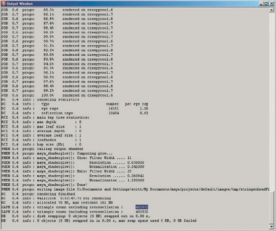
On the mental ray tab is a rollout option called Translation. Open this rollout and set Export Verbosity to Progress Messages. This will tell mental ray to report useful information to the output window when it renders. This includes the final Triangle count, which when divided by two is the face count of your subdivided model at render time. Compare this to the final face count in ZBrush to determine how close to the ZBrush subdivision you are getting with your Approximation settings (Figure 9.19). This can assist in setting your N Subdivision value accurately. Now open the render view and initiate a render. You can keep the image in render view for comparison (Figure 9.20). Figure 9.21 shows how raising the Approximation settings will increase the quality of the fine details on the surface.

In this section we'll look at rendering a character using multiple displacement maps. Multiple maps are desirable when you need higher resolution in the finished render so you can spread the entire character's detail across multiple maps. With this technique, you can have 4096x4096 pixels of displacement detail for the head, arms, and body as opposed to spreading the texture space across the entire model.
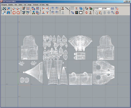
To generate multiple maps with Multi Displacement 3, it is necessary to set up multiple UV regions in Maya. This simply means your UVs lie outside the standard 0 to 1 range, which is displayed in Maya by the upper-right quadrant in the UV Texture Editor (Figure 9.22). When your mesh has UVs that lie outside the 0 to 1 region, clicking the Create All button in Multi Displacement 3 will start generating and exporting maps for each of these regions. Follow these steps to set up a ZTool with multiple UV regions:

To display beyond just 0 to 1, select View → Grid ~OP and raise the Length and Width value to This value may be higher or lower as needed. You may also want to set Grid Lines Every n Units to 1 to visually clarify where each region begins and ends (Figure 9.23).
To shift UVs from 0 to 1, select a shell and in the Maya command-line editor or the Script Editor, enter the following MEL command (note the uppercase letters):
polyEditUV -u 1 -v 0
This moves the shell one unit to the right and 0 up or down. Repeat for each shell you want as a separate map or UV Group, placing each in its own quadrant. Increment the U number for the number of quadrants to move in each direction.
Once your UVs are placed, export the mesh as an OBG file. This mesh can be imported into ZBrush for sculpting. If you have already sculpted your character, this model can be imported into an existing ZTool, swapping the UVs.
In this example, we created a separate map per body part to increase quality in the final product by allowing more texture space per body part and the use of multiple high-resolution maps. To assign the maps, we need to create a displacement shader for each map we'll apply to the model.
The model in this example has eight UV regions, so eight maps are generated. The resulting 32-bit TIFF files will be ready to apply to the mesh in Maya and should render exactly as seen in ZBrush. To make sure each map is applied to the correct region of the creature, open the UV Texture Editor.
Marquee-select one quadrant of UVs and choose Select → Convert to Faces (or press Ctrl+F9 on your keyboard). You can also select a few UVs from one shell and then choose Select → Select Shell to enlarge the selection to the whole UV shell. Now in the Hypershade, apply the shader with the corresponding map to the set of faces. You can quickly assign shaders to selected faces by right-clicking your shader in the Hypershade and selecting Assign to Selection.
Once the faces that correspond to the UVs in each region have their own displacement shader applied, you are ready to render. Because the Alpha Gain and Alpha Offset settings are the same for all maps, there will be no discernable seams between your maps (Figure 9.24). Be sure that the Alpha Gain and Alpha Offset values are correct for each file node on each shader.

Note
You can determine which map is for which quadrant by looking at the filename index number for each map: 1001 is for quadrant one, 1002 for quadrant two, and so on. Be sure to give your shaders descriptive names as you create them.
Note
Included on the DVD is a video demonstrating how to render 16-bit displacement maps in Maya. The process for setting up the shader is identical to that used for 32-bit maps. The difference comes in determining the Alpha Gain and Alpha Offset values for the displacement map file node.
Because a 16-bit map does not have real-world scale baked in, you must adjust the Alpha Gain and Alpha Offset values until the render appears correct. By using an expression for Alpha Offset, you can just adjust the Gain value and Offset will update. Set Alpha Offset to = - filenodename.alphaGain /2;. In this expression, replace filenodename with the name of the current file node. You can find this at the top of the Attribute Editor window when you select the file node (Figure 9.25). If the file node is called file2, use the expression = - file2.alphaGain /2.
Test-render your displacement. If your Approximation settings are correct, you will just need to raise the Alpha Gain value until the height of the displacement looks correct. Figure 9.26 shows the Pixologic displacement test head. This figure illustrates a ZBrush render of the test head on the left and a Maya render of the same head on the right. By adjusting Alpha Gain to increase the level of displacement, we can dial into the right settings. The render scene file for this test head is available on the DVD. Simply open the scene file in Maya and render.


In most cases, you will want fine details on your mesh such as pores and small wrinkles. You can add these into the geometry itself, and ultimately the displacement map, but that's not always the most efficient approach. With some preplanning, the finer details can be added in a bump map and rendered over the displacement in mental ray. This takes a huge load off the renderer since you don't have to subdivide nearly as high to get lower-frequency forms to appear. A good rule of thumb is if your detail will change the silhouette of the model, displace it. If it is not visible in the profile, add it as a bump map detail instead. ZBrush has a great tool for making bump maps in the Bump Viewer material. For more information on the Bump Viewer material, see Chapter It is also possible to load your displacement map into the bump channel.
You can also generate a bump map for your finer details in ZBrush by simply extracting a displacement map from a higher subdivision level than On a five-division mesh, try extracting a displacement from level 3 and using this as your bump map.
To apply your bump map in Maya, open the Attribute Editor for the material on your mesh. Here you'll see a bump mapping slot. Click the checker box to the right of the attribute name in the Attribute Editor and select File from the pop-up window. This will create a bump2D node. You will see some options in the Attribute Editor for the bump2D node. Bump Depth is the "volume" control for the level of the bump effect in rendering. The initial value of 1 is usually too high, so start testing with a value of 0.Render and adjust the Bump Depth value accordingly until you get a satisfactory result.
Click the arrow next to Bump Value to access the file node, where you will load your bump map. Remember just like the displacement map, this is based in 50% gray, so be sure to set your Alpha Gain value to 1 and Alpha Offset to –.5 under Color Balance in the file node.
Render your model to view the bump map effect on the surface.
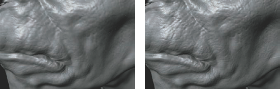
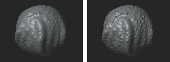
Figure 9.27 shows a character whose details exist only as a bump map. These can be indistinguishable from displaced fine details and in many cases superior since they require less render time to produce for the same visual effect. Figure 9.28 provides another example: the sphere on the left is fully displaced. The sphere on the right has a displacement map driving the form, while another displacement map loaded into the bump channel handles high-frequency details.

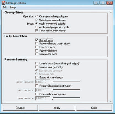
When you're preparing a model for sculpting and displacement extraction in ZBrush, the mesh needs to be clean. By clean, I mean it should consist of all quads (or at least nearly all quads). Avoid triangles, poles (points where five edges or more meet), and n-gons (faces with more than four vertices). If you find you must have a tri, hide it in an inconspicuous area. Tringles and N-gons may cause artifacts at render time. You also want to ensure your vertices are all welded and that there are no nonmanifold or lamina faces. All of these mesh issues can be resolved with the cleanup tool. Follow these steps before you start sculpting on the model as they will potentially alter the vertex order of the mesh.
Select Polygons → Cleanup
If you choose Select Matching Polygons in the Cleanup Effect section and check only the 4-Sided Faces option, Click the Cleanup button and Maya will select all the quads in your mesh. You can then use Edit → Invert Selection to select the nonquad faces. Often, I will assign another color to these faces to keep them visible and continue working the topology until I have an all-quad mesh.
Still in the Cleanup Options dialog box, choose the Cleanup Matching Polygons (in Maya 8.0 this option is called Select and Cleanup) and select Lamina Faces and Nonmanifold Geometry in the Remove Geometry section. Click the Cleanup button, and this will resolve any of the issues that often arise when modeling with the Extrude tool. Cleaning up your mesh now can save a lot of headaches later on.
In some cases you may see artifacts in your renders. If you see bloating in your render, then there is a mistake with the Alpha Gain and Alpha Offset values or the Alpha Detection setting in Maya 2008 is wrong (Figure 9.30). Usually you have forgotten to set one or both, or the Alpha Offset is not set to –½ Alpha Gain.

Figure 9.30. The bloating in this render is due to incorrectly set Alpha Gain and Alpha Offset settings.
Small spikes on UV seams can be remedied by using the Smooth UV option under Tools → Displacement. Use this only when creating an adaptive map. It has no effect in DPsubPix mode. Many artifacts are caused by bad topology in the underlying mesh. Triangles, poles, or faces with more than four sides can result in surface errors (Figure 9.31). These artifacts should be hidden in inconspicuous places during the modeling process or removed completely. If you find such an artifact on your render, applying a smooth to the mesh before rendering can help (Figure 9.32). Doing so will increase render time, and you may want to lower your Approximation settings as a result.


In this chapter, we explored the two major displacement map types that can be exported from ZBrush, and you learned how to set up models and shaders for displacement in Maya. By combining your texture map, displacement, diffuse, and bump maps with a subsurface scattering shader, you can achieve renders like the one shown in Figure 9.3The ability to capture the high detail of your characters in other renderers allows you to take your work to the next level, breathing life and animation into your work. In the next chapter, we'll continue looking at difference maps in ZBrush by discussing normal maps.