ZMapper is a plug-in that comes preinstalled with all versions of ZBrush after 3.0. ZMapper is a robust plug-in with many functions, including the ability to generate normal as well as cavity maps, and the ability to preview blend shape targets sculpted in ZBrush. In this chapter, we'll look at several uses for ZMapper.
ZBrush offers two methods of extracting your high-frequency details and then rendering them in an external application: normal mapping and displacement mapping. We have already discussed displacement mapping in Chapter 9.
Normal maps are color maps that represent the surface normal direction of any given point on the model. They allow a renderer to create the impression of a highly detailed surface on a low-polygon base. Figure 10.1 shows an example of a normal map and the rendered result on a model.
Normal mapping differs from displacement in one major way. While displacement mapping makes actual geometry at render time by subdividing the mesh, normal mapping creates the illusion of a highly detailed surface without changing the geometry. The benefit of this is speed, but the drawback is that the silhouette of the model will not change. In Figure 10.2, the sphere on the left is displaced while the sphere on the right is normal mapped. Note how the profiles are still angular on the normal mapped sphere.
For this reason it is imperative that the base model be optimized to best represent the overall profiles of the model when you will be normal mapping. If your low-polygon mesh is too low and does not represent the form of the high-res, you will end up with errors in your normal map at worst—or at least a normal map that is unconvincing when displayed on a faceted model.


Figure 10.1. This character is rendered with a normal map. This mapping method gives the low-polygon mesh seen on the left the appearance of high-frequency details, as shown on the right. (Image courtesy of Secret Level/Sega and Gentle Giant Studios.)

Figure 10.2. The model on the left is normal mapped while the right is displaced. Note the visible polygon facets on the silhouette of the normal mapped model (especially in the shoulder) and how the details do not translate into the silhouette. (Model by Jim McPherson)
Normal maps offer a superb way to create the illusion of a highly detailed surface on a low-polygon base. Normal maps are actually generated from bump maps when processing; this process is invisible to the user but understanding it will help you understand the inner workings of the normal map.
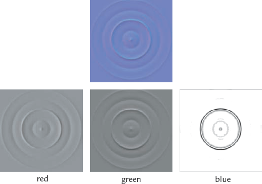
A normal map is an RGB image file. Each channel of the map (R, G, and B) represents one of the three axes (X, Y, and Z). In Figure 10.3 the individual channels of a normal map have been isolated to help illustrate this. The Red, or R, channel represents the surface lit from the right; the G channel represents light from above, or the Y direction; and B is light shining down the Z-axis.
To create a normal map in ZBrush, you will use ZMapper. There is an option under the Tool menu (choose Tool → Normal Map), but this is legacy inclusion in the program and does not offer the same control as ZMapper.
ZMapper is a ZBrush plug-in that comes preinstalled in versions of ZBrush from version 3.0 and up. ZMapper allows you to create normal maps with a full level of control over all aspects of the algorithm. Since there are no published standards for how programs interpret normal maps, all applications interpret them slightly differently. By giving the user full access to the generation process, ZMapper is an exceptional normal mapping tool. In addition to creating normal maps, ZMapper allows you to generate cavity maps, check blend shape animation, and check the UV layout on your model. Before we examine the ZMapper interface in depth, let's follow the process to load a ZTool and generate a tangent space normal map.
ZMapper is accessed by the ZMapper button in the upper-left tray of the user interface. Before ZMapper will launch, there must be a ZTool on the canvas in Edit mode. To load a model into ZMapper and generate a normal map, follow these steps:
From the Tool menu select a Plane3D tool and click the MakePolyMesh3D button. Draw the plane on the canvas and enter Edit mode by pressing the T key.
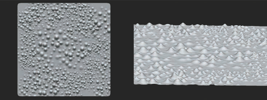
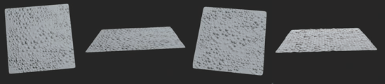
Open the main Tool menu, click the Morph Target menu to unroll it, and click storeMT to store a copy of the mesh at level Subdivide a few times with Ctrl+D and create some sculpted strokes on the model. Notice in Figure 10.4 that the surface of the plane is deformed and the bumps have actual height.
When you have finished sculpting, step down to level Click the main Texture menu and set your width and height sliders to 2048. Then click the New button. This will create a new 2048x2048 texture on the model. ZMapper will generate a normal map for whatever resolution texture is active when it launches. The plane already has implicit UVs, so you don't need to create those. In other cases, such as an imported mesh, you will always need to be sure the model has UVs.
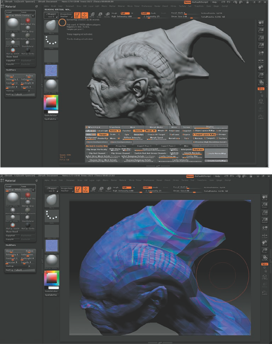
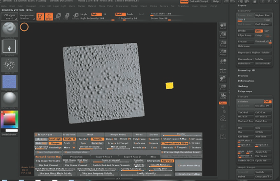
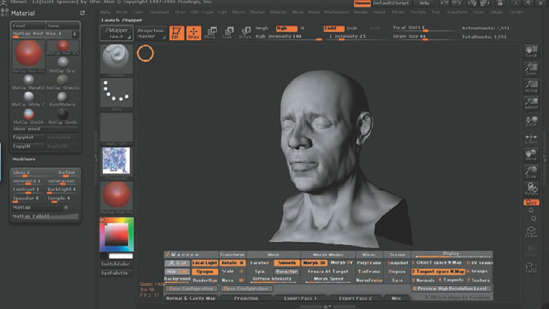
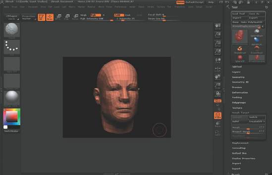
Click the ZMapper button to launch the application. The model will be spinning slowly at the center of the screen, and ZMapper's interface will appear in the document window (Figure 10.5). You can use the Tab key to show or hide the ZMapper menu.
Your model will default to having Spin on. This causes it to rotate on its axis after you move the model. Disable this now by clicking the Spin button in the Mesh column.
In the Display column, click the Tangent Space Normal Map button. Expand the Normal & Cavity Map tab by clicking its tab at the bottom of the ZMapper interface. This opens the basic normal mapping options.

You will now see the Create NormalMap button. Click this and the map will start to generate. You can see it update pixel by pixel on your model in the ZMapper view.
When the map is completed, it will display in ZMapper. You can rotate around the model and check the display. You may even move the light. In the ZMapper main menu, click the local light button. This activates a light you may rotate around the model. To move the light in ZMapper, Shift+left-click to rotate and Shift+right-click to raise up and down. If you move the light close to the model, you may see it displayed in the ZMapper window as a yellow cube (Figure 10.6).
Rotate around the mesh and note that the polygons have a slight elevation to them from your lowest subdivision level. We'll now switch back to the flat plane. Press Esc to exit ZMapper. Notice that the normal map generated is automatically loaded into the Texture menu.
Click the main Tool menu's Morph Target menu and select Switch. This will return the plane to its flattened state. Click the ZMapper button to launch the plug-in. Notice that the normal map still appears the same. Rotate the plane and see that it is indeed flat. The normal map gives the impression of depth and height (Figure 10.7).
Now you have completed the steps to making a basic normal map on a simple piece of geometry. We'll move on now to examine the interface more closely and experiment with some more in-depth examples.
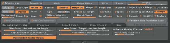
In this section, we'll examine the ZMapper interface (Figure 10.8). There are several tabs and menu options. This may look daunting at first, but you will soon see everything is in its place.
Navigation in ZMapper is similar to navigating in ZBrush itself. To rotate the model, drag the background. If the Spin option is on, the model will continue to move in the direction of the mouse movement when released. Panning is accomplished by dragging the background while holding the spacebar, and zooming is achieved by right-click-dragging the model or background.
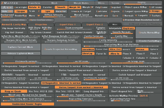
Figure 10.8. The ZMapper menu (here, with all the tabs locked open for a full view of the interface)
The ZMapper control panel is divided into two main sections. The upper controls remain consistent at all times. The lower tabbed controls are accessible from the various tabbed menus. These offer different menu sets for various aspects of the program.
The lower control tabs can be accessed by clicking the tab name. To lock a tabbed menu in the open state, Shift-click its name.
The upper menu is broken down into seven columns; see Table 10.1.
The lower control panel consists of several tabs. These control all aspects of the normal map generation process. The tabs and their function are explained in Table 10.2.
Table 10.1. Contents of the ZMapper Main Menu
Column | Controls |
|---|---|
ZMapper | General controls for the ZMapper interface. |
Transform | Controls navigation in ZMapper. |
Mesh | Controls the mesh display in ZMapper. |
Morph | Morph causes the model to dynamically shift between representations. Morph 3D will blend between the model and a stored morph target while Morph UV will unwrap dynamically to the UV map. |
Wires | Controls the wireframe display of the model. |
Screen | Allows screenshots to be stored and exported. |
Display | Controls both the type of view in ZMapper as well as the type of the normal map generated (Tangent or Object space). |
Table 10.2. Contents of the ZMapper tabs
Tab | Controls |
|---|---|
Normal & Cavity Map | Normal and cavity map general settings. |
Projection | Settings for generating a normal map between arbitrary meshes. |
Expert Pass 1 | The Expert Pass tabs allow fine-tuning of every aspect of the map-generation process. These are usually best left at the default settings unless you have specific technical needs in your engine. |
Expert Pass 2 | Same as above. |
Misc | Various options that done fit in other menus. The most important two are Doublesided Render Region and Raycasting Max Scan Distance, both discussed later in this chapter. |
The menus contain three kinds of controls: buttons, switches, and intensity controls.
Buttons, such as Exit or Create Normal Map, are shaded in gray; clicking these causes an action to occur.
Switches are shown in a darker gray. These turn an option on or off. The Spin switch will toggle the spinning rotation that is ZMapper's default display.
Intensity controls govern the strength of an option or effect. The Morph Speed slider shows this value set to 0 on the left and 100% on the right.
Normal maps do not have a published standard in the same way that displacement maps do. This means that all programs interpret them with subtle differences. It is for this reason that ZMapper has so many options open to you. Luckily ZMapper also includes the ability to create and store configuration files. Config files contain all the pertinent settings for the application or engine in which you will render your normal map.
To open a configuration file, click the Open Configuration button to see the default files that come standard with ZBrush. Most major application settings are represented here. If you are rendering Maya, select Maya Tangent Space Node Best Quality. This will configure ZMapper will all the necessary settings for a tangent space map to display in Maya.
If you have specific needs for your own engine or map, you can set your ZMapper settings and then click Save Configuration. This will store these settings in a file that can be shared between artists in a studio so all maps are consistent in their settings.
Often as you are generating normal maps, you may want to adjust settings and compare them to previous renders. You can save time by generating only part of the map at a time for comparison purposes. To do this, use the RenderRgn button under the ZMapper menu column.
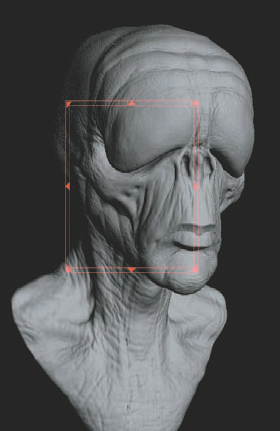
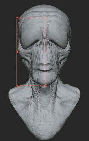
The Render Region feature allows you to generate just a portion of the normal map so you can quickly evaluate settings. In Figure 10.9, Render Region is active. Notice the red rectangle; clicking in the corners allows you to scale this selection rectangle to the area you want to render. Clicking inside the double box lets you move the rectangle around. If you click and drag inside the box, you can further refine the render selection with a lasso tool (Figure 10.10).
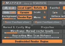
Some settings may increase the time required to generate the normal maps. Adjusting the Raycasting Max Scan Distance slider, for instance, can increase the time it takes for a map to complete. You can enhance the efficiency of the render region by turning off Double Sided so only those areas facing the viewer are rendered. On the Misc menu tab, click Doublesided Render Region to turn it off (Figure 10.11).

Let's use the render region to experiment with various normal map generation settings:
Turn on Render Region by clicking the RenderRgn button. Draw the rectangle around one side of the model, as shown in Figure 10.12.
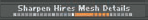
Under Normal & Cavity Maps, raise the Sharpen Hires (high-resolution) Mesh Details slider. This will sharpen the detail as the map generates.
Click Create Normal Map. The map will generate for just the area inside the region (Figure 10.13). You can easily compare the result of these settings to the previous render on the other side of the face.
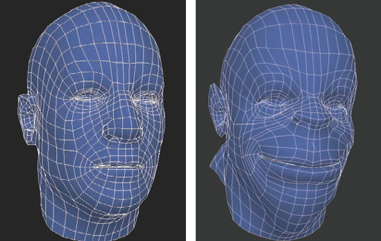
When transferring high-res details from one ZTool to a low-res mesh as a normal map the most common approach is to sculpt the high resolution model first. When this model is completed a low-res animation friendly model is made either in ZBrush or in another application. When building the low-res model always take care that the edges are placed on the highest and lowest points of the silhouette. This helps to ensure that while the internal forms will appear highly detailed by the normal map the overall outline of the character will not have an overtly faceted or low polygon look. Failing to make the most efficient use of your edges in the silhouette can be a dead giveaway to the low poly nature of the mesh and ruin the illusion of the high-resolution appearance.
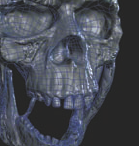
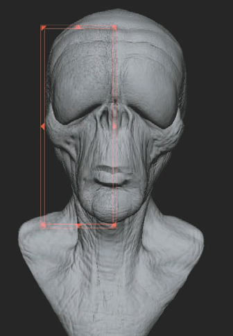
This approach also allows you to finish sculpting before you have to worry about topology. ZMapper lets you generate normal maps between two separate meshes just as if they were one ZTool. In this section we'll load a design sculpt and a remeshed game mesh, and create a normal map between the two (Figure 10.14).
Load the original ZTool. We'll call this the design sculpt since the topology is not the final that you'll want to use as the base model. This should be a multi-resolution ZTool with all your sculpting applied. For this demo, load
humanhead.ztlfrom the DVD.Choose Tool → Texture and click AUV Tiles to generate texture coordinates for the design sculpt. Launch ZMapper by clicking the ZMapper button.
Open the Projection tab at the bottom of the screen. You'll want to capture the details of this design sculpt and then project them into a new topology that follows the same overall shape of this mesh. Turn up Raycasting Max Scan Distance halfway. This is the length each ray will cast trying to find the difference between the two meshes: the design sculpt and the remesh (Figure 10.15).
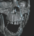
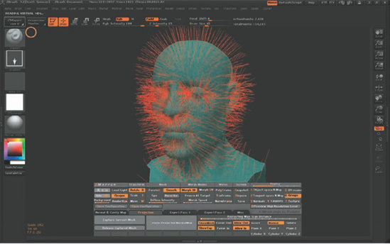
Click the Capture Current Mesh button. The model will now be covered in red lines; these are the normals of the current mesh captured (Figure 10.16). Exit ZMapper by pressing the Esc key.
We now need to load the new mesh onto which we'll project this detail. I have created a lower-polygon version of the human head model, which is on the DVD. To import it into the current ZTool, select Tool → Clone to make a copy of the current mesh. Under Tool → Geometry, click Del Higher to delete the higher subdivision levels so there is only one.
Now import the
humanheadlow.objfile into the current ZTool. This will ensure the pivot and scale remain the same while swapping topology.Note
An alternative method is to have the two meshes as subtools. After capturing the high-res details, switch to the subtool of the game mesh and re-enter ZMapper.
Open ZMapper again. Under the Projection tab, you can turn off Show Cap to remove the red normal lines. Click Create Projected Normal Map to generate a normal map between the design sculpt and the new topology. When completed, the map will display in ZMapper (Figure 10.17).

Cavity maps are specialty textures that can be generated in ZMapper. They are essentially the blue channel of a normal map and represent dark shading in the crevices of the model. They can be useful as a multiply layer over a diffuse color map to accentuate details or as a diffuse map in Maya to help punch up the high-frequency details in a render. Figure 10.18 shows a cavity map. It is essentially a black-and-white map in which black represents the recesses and white is the high points.
Cavity mapping is intended to help mimic Ambient Occlusion, but it is not by nature an Ambient Occlusion effect. It also has several other uses. Ambient Occlusion works by casting rays out from the surface of a 3D model. If a ray hits another surface before dying out, then a grayscale value is recorded that represents how far that ray traveled before being occluded. This is how Ambient Occlusion maps generate darker shadows in tight recesses like inside ears or under the brow ridge. The rays there intersect the next surface faster than, say, faces under the chin, which would record a lighter grayscale value.
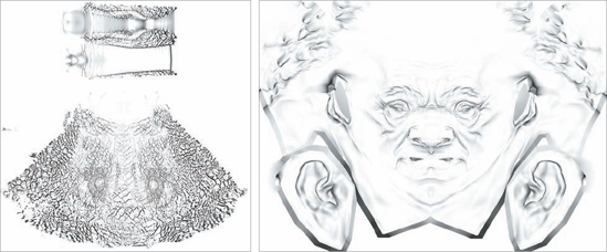
Cavity mapping, on the other hand, just shades in recesses. It doesn't use advanced raycasting or calculate distances between surfaces. It is, however, useful as a diffuse map or a Photoshop mask or any other application where you want to isolate the high points from the low points on a surface texture. Figure 10.19 shows a cavity map and Ambient Occlusion map to help illustrate the differences.
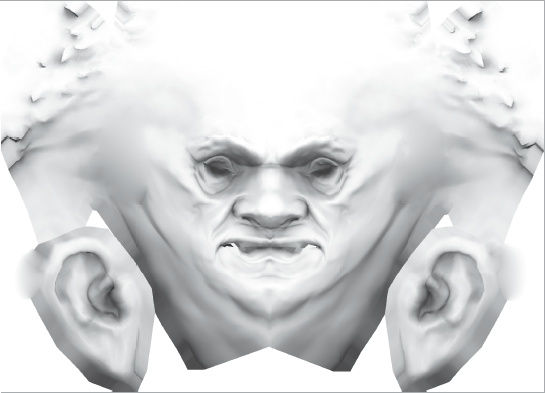
Figure 10.19. A cavity map and an occlusion map. The first image is a cavity map. Notice how the recesses are shaded while the Ambient Occlusion image shows a gradient shading into the recessed areas of the head.
Cavity maps are generated with ZMapper under the same Normal & Cavity Maps tab. To generate a cavity map, simply raise the Cavity Intensity slider to around the halfway point and click the Create CavityMap button (Figure 10.20). The map will generate on screen just as the normal map did before. When the map is completed, it will display on the model in ZMapper. Exit ZMapper and export the map from the Texture menu.
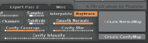
Figure 10.21 shows a cavity map used in the diffuse channel of a Maya Blinn shader. The cavity map is perfectly suited to help accentuate the rendered details by governing how light is reflected back from the surface. The dark areas reflect less light, so they appear darker; the lighter areas have the opposite effect. This effect helps accentuate the recessed areas by limiting the amount of light they reflect, giving them a darker, more-shadowed appearance.
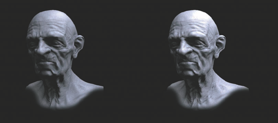
Figure 10.21. This character head was rendered in mental ray using a displacement map and a cavity map in the diffuse channel. The first image is the render without the cavity map; the second image is with the cavity map.
Note
You can view your UV in ZBrush by using ZMapper. To verify your UVs in ZMapper:
From the DVD, import the
body.objfile. Choose Tool → Import and browse to the body file.Draw the OBJ on the canvas and enter Edit mode by pressing the T key.
With the tool active on the canvas, click the ZMapper button in the upper-left corner of the screen.
At the bottom of the screen, you will see the ZMapper interface (Figure 10.22). For now we are concerned with the Morph UV button at the bottom.
The Morph UV button will cause the model to unwrap on your screen into its UV coordinates. Click the Freeze at Target button to freeze the UV display. Click and rotate in the interface somewhere off the model to rotate.
This process helps you quickly verify the UV layout on a ZTool. In ZBrush it is possible to swap UVs at any time by simply importing a new model into level Press Esc to exit ZMapper. In the next section we'll change the current UV layout by importing a different UV set.

In this section we'll generate a normal map in ZMapper using the Maya Tangent Space Node Best Quality configuration file. We'll then move to Maya where we'll set up shaders and render the normal map (Figure 10.23).
Open your ZTool in ZBrush. Draw it on the canvas and enter Edit mode. Step down to the lowest subdivision level. Assign AUV tiles by selecting Tool → Texture and clicking the AUV Tiles button. Create a texture in the main Texture menu. Set the resolution to 2048x2048.
Click the ZMapper button. From the ZMapper menu, click Open Configuration File. Select Maya Tangent Space Node Best Quality. This will automatically set up ZMapper for Maya. Click the Normal & Cavity Maps tab to open this menu. Click the Create Normal Map button.
When the normal map finishes generating, exit ZMapper by pressing Esc. The map will load into the Texture menu. You may notice it no longer displays correctly on your ZTool. This is because ZMapper was set to Maya configuration, which will flip the texture map vertically so it renders correctly in Maya. From the main Texture menu, export the normal map as a TIFF file. Open the main Tool menu and export level 1 of your ZTool as an OBJ.
When exporting OBJ files from ZBrush, be sure to adjust the following settings:
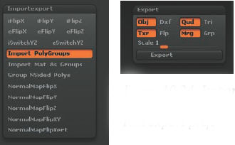
In Preferences → ImportExport, make sure that all the iFlip and eFlip options are off (Figure 10.24).
Under the main Tool menu, click the Export menu and make sure Mrg is on and Scale is set to 1.
This will merge your UVs on export. These settings will maintain your object scale and orientation.
Now that you are familiar with the process of generating the normal map in ZBrush, we are ready to move into Maya and render this character with a normal map applied.
Open Maya. Import the OBJ file of your level 1 mesh by choosing File → Import →

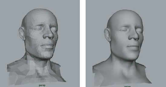
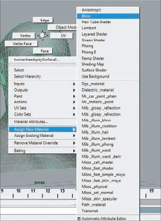
Select the mesh, and under the Polygons menu, click Normals → Soften Edge. This will soften the edge normals and give the faceted model a smooth appearance (Figure 10.26). Right-click the model, and from the Marking menu, assign a new shader and select a Blinn (Figure 10.27). This creates and assigns a new Blinn shader to the object.
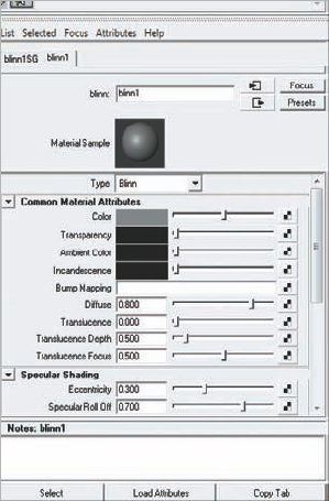
Press Ctrl+A to bring up the Attribute Editor. Select the Blinn shading node (Figure 10.28).
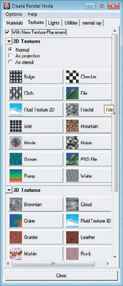
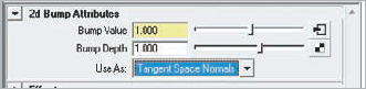
In Maya, normal maps are loaded into the bump channel. Click the check box next to the bump slot in the Blinn shader. In the Create Render Node window, select File (Figure 10.29) to attach a file node to the bump slot in the Blinn shader. This will open the bump 2D node pictured in Figure 10.30. Change the Use As value to Tangent Space Normals (Figure 10.31). This tells the renderer to interpret the bump map as a normal map and not as a grayscale map.
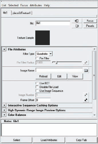
Click the downstream arrow next to the Bump value. This will open the file node driving the bump map node (Figure 10.32). Here you can load the normal map. Click the file browser menu icon and select the normal map exported from ZBrush.


That completes shader setup. Now create a directional light by clicking Create → Lights → Directional. Rotate this light to illuminate the model. You can switch to lit view by pressing the 7 key on your keyboard. Maya is capable of displaying the normal map in the viewport. To turn on normal mapping, click Renderer in the Viewport menu and select High Quality Rendering. Select Shading and click Hardware Shading. The normal map will now display in the viewport. The map can be rendered like this using hardware shading or through the mental ray renderer. Figure 10.33 shows this character rendered in the viewport as well as in the software renderer using Final Gather and Image Based Lighting.

Figure 10.33. This character head is rendered with a normal map. The first image is the normal map with wireframe in the Maya viewport. The second image shows the normal map rendered in the Maya viewport. The third image is the normal mapped mesh rendered in mental ray with Final Gather and Image Based Lighting.
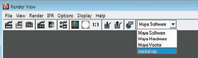
To render the normal map with mental ray, choose Window → Rendering Editors → Render View, and select mental ray as the renderer (Figure 10.34).
Congratulations! You have now created and applied a normal map in Maya.
Featured Artist: The Art of Joel Mongeon
Joel Mongeon's "Studio Wall" series caught my attention at SIGGRAPH (Special Interest Group on GRAPHics and Interactive Techniques) 200Taking a classic sculpture exercise and translating it into digital, Joe has created an exciting and inspiring image as well as demonstrated a valuable sculpting exercise.

ZMapper does more than normal and cavity maps. It is also a useful tool for checking blend shape animation on targets sculpted in ZBrush. Blend shape animation is an animation technique in which two versions of the same model are added as deformers to a base. This allows you to blend between the different vertex positions to create a variety of shapes on a single mesh. It is most commonly used for facial animation. With its organic sculpting tools, ZBrush is ideal for sculpting facial animation targets. ZMapper allows you to view the animation between a base and your blend shape target.
For example, we'll use a human head that transforms into a monster. Both models are sculpted from the same base mesh. Load the human head base into ZBrush.
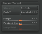
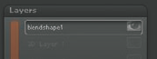
Load the base model into ZBrush. This is your neutral base (Figure 10.35). Store a morph target by choosing Tool → Morph Target (Figure 10.36). Under Layers, create a new layer and call it blendshape1 (Figure 10.37).
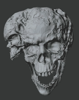
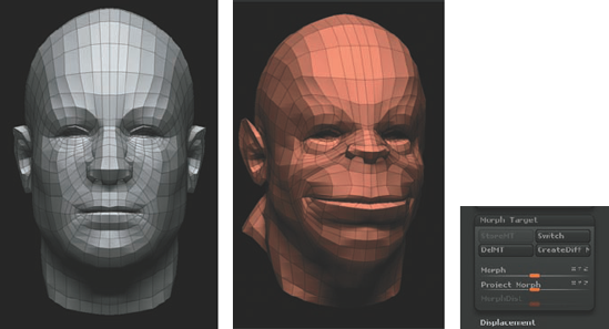
Using the standard sculpting tools, create a new character head from the base. These changes are stored on the blendshape1 layer since it is active. Change the human head into this beast (Figure 10.38). You can switch between this shape and the original with Tool → Morph Target → Switch.
With a base head and a morph target stored, you can now check the smoothness of the animation between the two when they are exported to Maya, 3ds Max, or another application. ZMapper uses the same interpolation as any other blend shape animation software so you can easily check the skin for realistic deformations or look for erroneous stray movements in vertices.
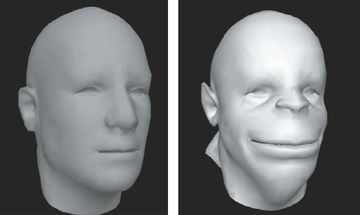
Load ZMapper and turn on morph3D under the Morph Modes column. The model will now blend between the base shape and the stored blend shape (Figure 10.39). If there are any problems in the animation, they will be apparent now instead of much later when the heads are exported to Maya and loaded into a blend shape deformer. You can even turn on Polyframe mode to check that the vertices all move in an evenly distributed manner (Figure 10.40). This is a huge time-saver and helps the sculptor use the tools to create subtle interesting skin deformations in blend shapes. Let's now add a new blend shape.
Export level 1 of your base head as an OBJ and call it
headbase.obj. Turn off the blendshape1 layer. Switch to the morph target stored and click delMT so that the creature head is on your screen.We'll now open the mouth and store this shape in a new layer as well as a blend shape. Storing the shapes in layers allows you to always access a morph target since ZBrush will only store one morph target at a time. Create a new layer; call it
open mouth monster.Using the Move brushes and masking, open the mouth. When the position is correct, click storeMT. Now you can open ZMapper and check the animation. Often when animating faces it is desirable to have the edges move slightly from all areas around the movement's center. This helps create the illusion of elastic skin instead of localizing the motion to a central point, which is very unnatural. Try using the Nudge brush to slide the skin of the cheeks back as the character smiles.
Plateaus or flattened areas in your normal map represent points where the ray faded before it was able to intersect the high-res mesh. This occurs in areas of large protrusion where the high-res is pulled far away from the low-res cage. See Figure 10.41 for an example of this kind of map artifact. They will appear as blank spots in the normal map.
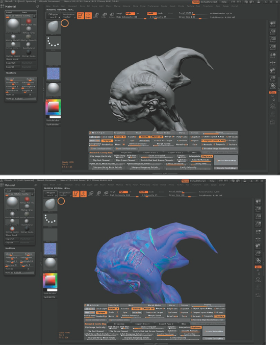
Figure 10.41. Plateau artifacts are caused by a high-res mesh that differs too much in shape from the low-res.

When this happens, the map will create a blank flat plane in the areas where the ray never intersected the second mesh. To correct, this you can simply raise the Raycasting Max Scan Distance, which allows rays to live longer and gives them more time to intersect the second mesh.
To correct for this, raise the Raycasting Max Scan Distance slider under the Misc tab (Figure 10.42). Figure 10.43 shows the effect raising this value has on the plateau areas of the map.