In this chapter we'll look at the ZBrush Transpose tools as well as the Topology tools. We have used Transpose in earlier chapters to move subtools, but we'll now take a more in-depth look and use Transpose as a dynamic posing tool. Using layers, we'll store multiple poses in one ZTool. We'll also look at the ZScript Transpose master for posing a model with multiple subtools.
The Topology tools will be used to rebuild the underlying geometry of our ZTool while retaining all the sculpted details. This allows you maximum freedom when working in ZBrush since you can sculpt and even PolyPaint a model, and then use the Topology tools to rebuild the base mesh and project all your detail and painting. The topology tools are also useful for building accessories like costumes and armor parts for your models.
Transpose tools are accessible when you have a tool active in Edit mode on the canvas, but you leave Draw mode and enter Move, Rotate, or Scale by clicking the corresponding buttons at the top left of the screen (or using the Q, W, E, R hotkeys: Q is for Draw mode while W, E, and R are for Move, Scale, and Rotate, respectively).
Note
In previous chapters we have used Transpose for moving subtools in relation to one another. Here we'll combine Transpose with masking and use it as an advanced posing tool. ZBrush allows us to create dynamic poses for our ZTools, store them in layers, and even maintain sculpting symmetry on an asymmetrically posed model. For a video demonstrating Transpose in action, please see the DVD.
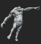
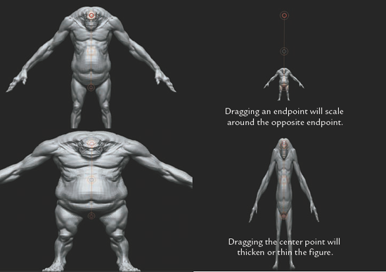
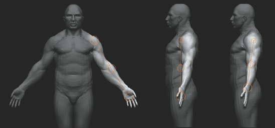
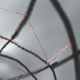
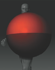
The Transpose tool consists of a single modifier called the Action line. When entering a Transpose mode, this line will be apparent on the model (Figure 7.1); you can redraw this line by clicking anywhere on the object, then dragging and releasing. The length of the stroke determines the length of the action line, and the places that you start and end the line determine the pivots for rotation and scale operations. When you're drawing an action line, it will snap to the surface of the model underneath it and any previous action lines will be replaced. Note that by default the size of the endpoint circles will change to help illustrate how far one endpoint is from the viewer compared to another. This can help you spot when the transpose line is receding into space from the viewer.
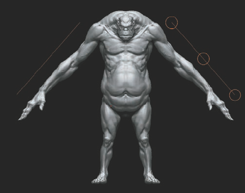
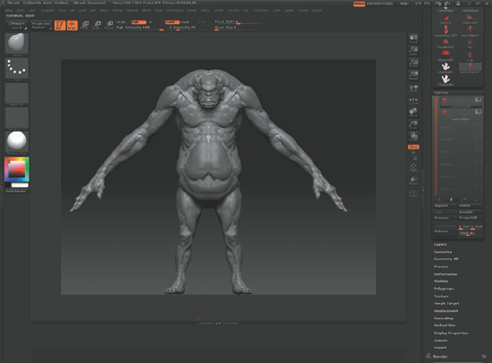
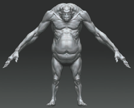
Figure 7.1. The action line is an orange line with three circles that is visible when in Move, Rotate, or Scale mode. (Giant by Jim McPherson courtesy of Gentle Giant Studios and Secret Level/Sega)
Transpose can be used with symmetry on or off; in Figure 7.1, both arms have an action line applied in Symmetry mode, if we turned Symmetry off, the line on the left arm would vanish.
You can reposition the action line by clicking and dragging on the line itself or on the yellow rim of the center circle. The circle endpoints can be adjusted by clicking on the circle, not inside the circle, to move them in the plane of the screen (X and Y directions only).
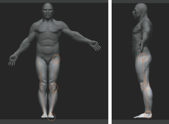
To center an endpoint in a joint, Shift-click-rotate to snap the model to a front view and place the endpoint. Then, Shift-rotate-snap to an orthographic side view and pull the endpoints back to the desired placement (Figure 7.2).
Figure 7.2. To center a joint: (a) Draw an action line in the front view. (b) Snap to an orthographic side view. (c) Move the circles from the side to place them correctly in relation to the figure.
To use the action line, click and drag from the center of one of the endpoints. You will know the endpoint is active when a red dot appears in the circle. With Move active
To scale an object, make sure Scale is active at the top of the screen by clicking the Scale button
Note
The Alt key will produce alternate effects in Transpose mode. Holding down the Alt key while scaling a figure will affect the parts of the model closest to that endpoint more. This could have the effect of lengthening the legs while leaving the rest of the figure relatively unchanged. Alt-dragging the midpoint will increase the scale effect between the midpoint and the last touched endpoint.
To rotate the model with Transpose active, enter Rotate mode by pressing the R hotkey or by clicking the Rotate button
When rotating in Transpose it is sometimes important to keep the action line straight and perpendicular to the viewplane. To do this, start the action line on the model but drag off the model to release. This ensures the line snaps to a plane perpendicular to the viewplane, thus allowing you to make accurate rotations in X, Y, and Z (Figure 7.5).

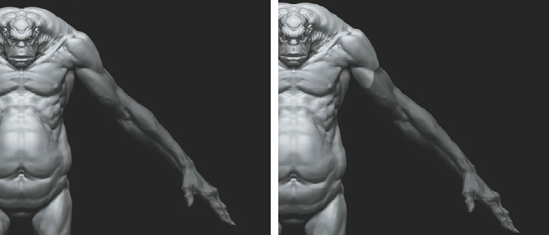
Figure 7.6 shows a figure with an action line drawn down the arm. If we enter Rotate mode and drag the endpoint, the entire figure will rotate. This is where masking comes in handy. By masking everything but the arm, the unmasked areas will rotate around the opposite end of the action line. Masking can be accomplished with the same methods we have discussed so far (Ctrl-clicking to paint masks or using a marquee).
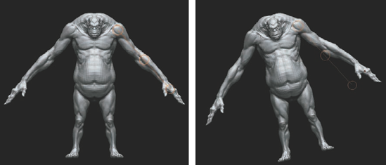
Figure 7.6. Rotating an unmasked figure is a global operation. With the body masked, only the arm rotates.
In Transpose mode, there is another powerful masking option called topology masking. Topology masking creates a mask on the model based on the underlying edge flow (Figure 7.7). In a base mesh with evenly dispersed quad geometry and edge loops that flow down the appendages, this makes masking limbs quick and easy. The topology generated by ZSphere models is especially effective with this masking technique.

To mask by topology, hold down the Ctrl key and drag the arm. Notice that the line produces a mask that dynamically grows with the stroke. With the entire arm masked, Ctrl-click off the model and invert the mask so the arm is now unmasked. The edge of the mask can be blurred or sharpened using the Ctrl and Shift keys (Figure 7.8). Ctrl-click the masked area to blur it and to create a more natural deformation; Ctrl+Alt-click to sharpen the masked area. This can also be accomplished with the blurMask and sharpenMask buttons under Tool → Masking. You can adjust the amount of blur or sharpening that is applied when you Ctrl-click by choosing Preferences → Transpose. Topology masking is only accessible when Move, Rotate, or Scale mode is active.
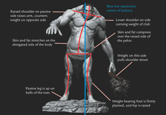
When posing a character, keep in mind some fundamental concepts. Where is the character's center of balance, where is the weight of the character placed in relation to the center, and how is the character's anatomy changing over the pose (meaning the extension and compression of the muscles)?
In Figure 7.9 I have labeled the skeleton, the center of balance, and the weight distribution on this character. The red lines represent the underlying skeleton. Notice that the left hip is raised with the weight being placed on the left leg. This shifting of weight across the center line is called contrapposto. The blue line represents the center of gravity; this is always a straight plumb line and is not necessarily in the center of the figure. Notice that the line of the hips is at an angle opposite that of the shoulders.
In this section we'll use the information you have learned about Transpose and topology masking to pose a character ZTool. We'll store this pose in a ZTool layer much like we stored detail passes in Chapter 4. This allows us to always return to the neutral posed version of the character.

Start by loading the
demosolider.ztlfile from the default ZTools folder. This is one of the ZTools that comes installed with ZBrush. This particular mesh is well suited to topology masking because of the edge layout. Notice in Figure 7.10 how the arms and legs are all composed of repeated rings moving up the length of the limb.Open the SubTool menu under the main Tool menu and delete all the subtools, leaving just the body. Divide up to the highest possible subdivision level and create a new layer. Name this layer pose. Remember that layers can only be created at one subdivision level, so always make them at the highest possible polygon count. Changes made at lower subdivision levels will still store in the active layer.
Step down several subdivision levels. Transpose posing is more difficult when the mesh is dense. It is not necessary to have thousands of polygons when you are simply posing the model.
Ctrl-drag a mask from the arm to the chest. This is masking by topology. You may also enter Draw mode (the Q key) and paint the mask directly as you would normally. Once the arm is masked, invert the mask so that the body is masked and the arm unmasked by Ctrl-clicking the background.
With the arm unmasked, draw a transpose line from the shoulder to the wrist. Move to a side view and place the endpoint where the arm should pivot (Figure 7.11).
You can now rotate the arm using the endpoint on the action line.
Repeat this process for the legs, but this time turn on X Symmetry with the X hotkey. Notice how two action lines are created, and you can move the legs together (Figure 7.12).
Let's add a forearm twist. Mask down to the elbow and draw an action line from the elbow to the wrist. Click in the wrist endpoint, then Alt-drag in the center point. Since we clicked in the wrist endpoint, the rotation will be concentrated in the forearm and give us a nice twist (Figure 7.13).
We'll use bone posing for the elbow bend. Bone posing is a built-in skinning algorithm that stretches faces on one side of a pivot while compressing them on the other. This helps approximate the deformation of skin and muscle around a skeletal joint (Figure 7.14). Draw a transpose line from the shoulder to the elbow. Be sure there are no active masks. Alt-drag in the last endpoint, the one at the elbow. This will bend the arm, but it will have the effect of bulging the bicep and stretching the elbow skin. This kind of built-in skinning algorithm helps you quickly create natural poses.
When you have finished posing the character, step back to the highest subdivision level where you created the pose layer. Under Tool → Layers, turn off the pose layer by clicking the eye icon. The figure will now return to its default pose. If you click the eye icon again, the figure will return to its pose.
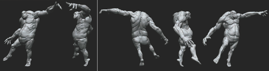
Figure 7.15 shows a figure posed entirely with Transpose.


Adjusting the Intensity slider can have unexpected results since the blend is closer to a blend shape deformer than rigged animation. The figure will blend between its two positions by letting the vertices take the shortest path. The Intensity slider works exceptionally well when storing blend shapes for facial animation in layers (Figure 7.16). ZBrush can be used to sculpt facial animation targets; adjusting the intensity on the layer allows you to export different intensities of targets as well as blend target layers together.
When posing your figures, keep in mind some artistic considerations. Most important is to maintain a sense of weight distribution over the center of balance. Make sure you know where the character is balanced; otherwise it will not appear to have weight and may look like it is simply floating in air. Also keep a sense of gesture while you pose. Gesture, as you recall, is the most important aspect of effective figure work.
Although many parts of the body change during posing, there are others that it would be ideal to be able to sculpt with Symmetry turned on—such as the face or the bony masses of the body, like the pelvis and ribcage. ZBrush's posable symmetry feature lets you keep Symmetry on when posing a model asymmetrically. This symmetry is calculated based on the topology, so your model must have symmetrical topology for it to function. To use posable symmetry, click Transform → Activate Symmetry and click the Use Posable Symmetry button (Figure 7.17). Your cursor will turn green, alerting you to the fact you are in posable symmetry mode. This is a great tool for sculpting fingers, faces, or any other areas that maintain a level of structural symmetry when posed.

Transpose Master is a plug-in from Pixologic that allows you to pose meshes with several subtools. Transpose itself will only pose a single subtool at a time; Transpose Master will create a new ZTool with all the subtools combined into a low-resolution proxy model. Using masking to selectively isolate parts, you can pose the entire character, and then with the click of a button, you can transfer this information to the original ZTool.
You can download Transpose Master from http://www.zbrushcentral.com or http://www.pixologic.com. Install it as you would any other ZBrush plug-in, and use these steps to pose a complex model using Transpose Master:
Load the
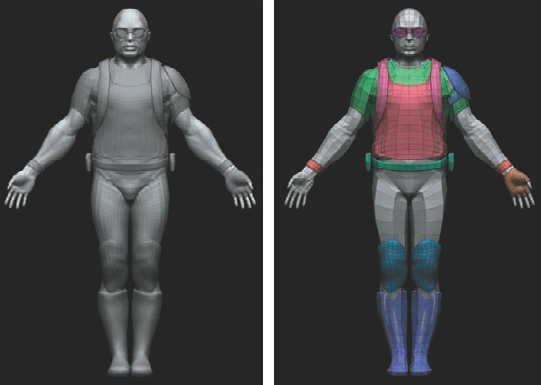
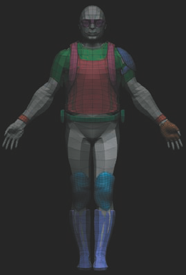
Demosolider.ztlfile from the default ZBrush ZTools directory. This time don't delete the subtools. Make sure the ZTool is active in Edit mode on the canvas. If you have installed Transpose Master, you will now have a Transpose Master menu under the ZPlugin menu. This menu consists of two buttons: TPoseMesh and Tpose>SubT. TPoseMesh will create a new proxy ZTool of your character with all subtools as a single object. This proxy will be created at the lowest subdivision level, and it is this mesh we'll pose. The TPose>SubT button will transfer the pose from the TPoseMesh to the original multisubtool mesh.Click the TPoseMesh button. The script will now generate a proxy posing mesh. The subtools and the main figure will all be one object, but each subtool will have its own polygroup to make hiding and masking easier (Figure 7.18).
By using masking in conjunction with polygroups, you can effectively pose the proxy mesh with the attachments. In this example, you'll pose the legs. The leg consists of the leg itself, the kneepad, and the boot. Ctrl+Shift-click the body to hide all other polygroups, and then mask down to the right leg. Ctrl+Shift-click the background to view all polygroups again, and using the masking marquee, mask the attachments, leaving the boot and kneepad on the left leg unmasked. Remember, you can isolate polygrouped parts with Ctrl+Shift-click to make masking easier. Once the rest of the parts are masked, the leg and its accessories are ready to transpose (Figure 7.19).
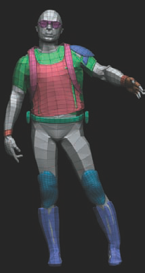
Draw an action line down the leg and pose by moving the endpoint. Notice that the unmasked accessories follow as they too are linked to the action line since the proxy mesh is a single polygon object (Figure 7.20).
Repeat this process for the arm, masking all other parts of the body and posing the arm and its accessories. Note that the undershirt is masked to the shoulder so that the sleeve will deform with the arm as it raises.
The head follows the same process for posing. Mask all but the head and those accessories you want to pose, using a Transpose action line pose as desired. When posing fingers, you'll find it helpful to hide all the other accessories since they will not be moving; this saves the trouble of repeatedly masking them. Figure 7.21 shows the final proxy pose of the demo solider character.
You are ready to transfer the pose from the proxy mesh to the original ZTool. Under ZScript → TransposeMaster, click the TPose → SubT button to transfer.

The ZBrush Topology tools allow you to build new geometry directly on top of an existing ZTool. You achieve this by making chains of ZSpheres that represent the polygon edges using the original ZTool as a template or base. Building new geometry in this way makes it possible to create costume elements that are custom fit to your characters. It is also possible to use the projection feature to shrink-wrap your new topology to a high-res Ztool, effectively capturing all your sculpted details while completely rebuilding the underlying topology. This is a huge advantage since it is not possible to change topology in a ZTool without losing all your sculpting detail. There are two reasons you may want to change the model's topology: You might want to adjust edge flow to remedy polygon stretching or loss of detail, or you may want to create an animation-ready mesh for use in an external animation and rendering package.
Note
This tool allows you to start a character from just a polygon sphere and carry it all the way through to PolyPainting. By using projection in topology, you can project not just sculpted details but painted color as well. In the following section we'll rebuild the topology of the head from Chapter 2 into a mesh that can be animated. The process of rebuilding a model's geometry is called retopologizing, or more commonly remeshing. For a video of this tutorial please see the DVD.
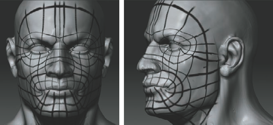
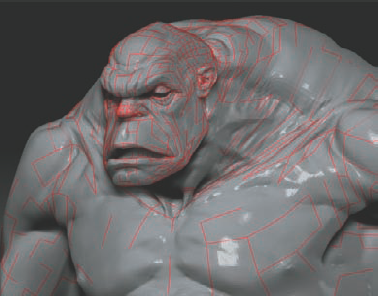
When you're trying to build an animation-ready mesh on your ZTools, it is often useful to have the topology planned out ahead of time using the PolyPaint tools. By PolyPainting the edge flow on the head first, you can work out topology issues ahead of time. Having the edge flow drawn on with PolyPainting allows you to trace the lines when you are using the Topology tools, which is simpler than trying to plan and execute a remesh on the fly.
With the head sculpt in Edit mode, turn on Colorize under the main Tool → Texture menu. Select the Standard brush and make sure only RGB is on.
Select white in the active color palette. Choose the main Color menu, and click the Fill Object button. This will fill the colorized head with white so you can draw the edge flow plan over it in black.
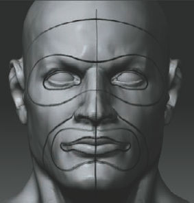
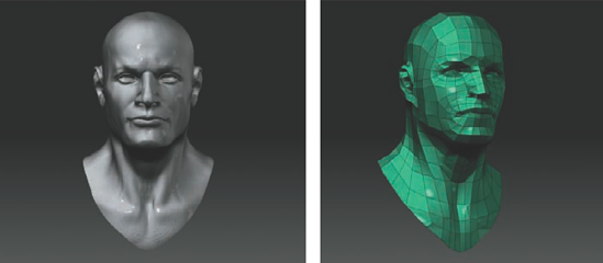
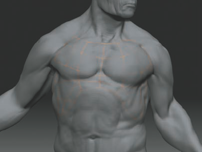
Switch the active color to black and turn on X Symmetry by pressing the X key. Begin by drawing on the eye and mouth loops, as Figure 7.22 shows.
Establish the main loops you want in the topology around the eyes, mouth, and overall face. Edge loops assist in animation, ensuring the mesh can be deformed naturally with minimal stretching. Usually you want major forms to be contained with edge loops (Figure 7.23).
Note
When drawing complex areas like the ear, switch to red. Drawing these edges in red makes them easier to spot in tight areas.
Continuing with the Simple brush, sketch in the remainder of the topology (Figure 7.24). When you are done, save the ZTool. The PolyPaint color will save with the file here.
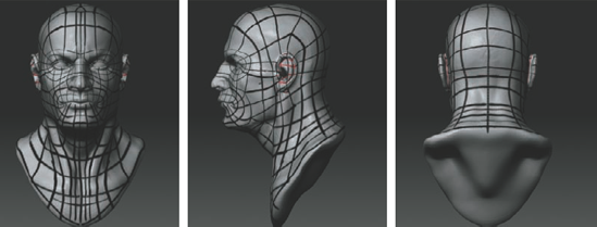
When planning the edge flow for an animation mesh, keep in mind how the character will move. The areas on a face that are the most mobile are the eyes and mouth, so naturally these areas are edge loops to allow a more natural movement from the face. There are many schools of thought on proper topology for a face and body, and most studios or setup artists have their own preference. The best way to learn about topology is to look at the meshes of others and experiment building your own. Gnomonology (http://www.gnomonology.com) has animation meshes available for purchase, and many online forums offer free samples. Sculpting facial animation targets and applying them in Maya will help illustrate what kinds of topology work best. Just like with sculpting, experience is key to getting a handle on this discipline.
Now that we have the topology planned out in the form of a PolyPainted template, we are ready to start using the ZBrush Topology tools. The Topology tools are based on ZSphere chains, so we'll start by creating a ZSphere as the root. Follow these steps to remesh a character head:
Drop any tools and clear the canvas. Make sure that the head ZTool with the PolyPaint topology is loaded in the Tool menu but not active on the canvas. From the main Tool menu select a ZSphere

This sphere will be the root of your topology chain. You'll link this sphere to the mesh you want to use as the base for your Retopology. With the ZSphere on the canvas in Edit mode, open the main Tool menu and dock it to the side screen by clicking the radial button

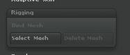
Scroll to the bottom of the Tool menu and you will find the Rigging menu (Figure 7.25). Click Rigging to expand this menu. Click the Select Mesh button to open the Tool palette; from there, select the head ZTool. This will link the head tool to the root ZSphere and specify it as the base for your topology tools (Figure 7.26).
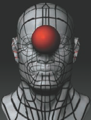
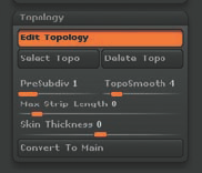
Under the main Tool menu, click the Topology menu to unroll it (Figure 7.27). Click the Edit Topology button. The ZSphere will now disappear and the head will be visible. There is a small red circle in the center of the head (Figure 7.28); this is the root ZSphere (Figure 7.29).

Figure 7.28. When edit topology is active, the root ZSphere disappears and the ZTool is ready to accept new topology.
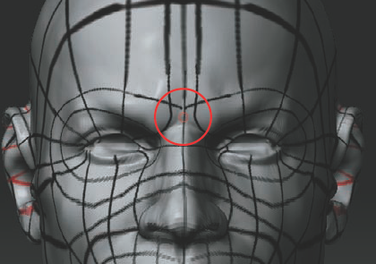
Figure 7.29. The root ZSphere appears as a red circle; make sure you deselect it or your topology could have problems.
Note
When drawing topology, make sure the root ZSphere is not selected. After each face is drawn, double-click on the background to make sure the root sphere is not selected. Failing to do this can create floating faces and other random geometry that connects to the center of the model.
Change to the Fast Shader and raise the Ambient modifier under Material to get rid of shadows to make it easier to see the edges as you draw them. Turn on X Symmetry and start to trace the topology drawn on the model. Draw a four-sided face and double-click off the model surface (Figure 7.30).
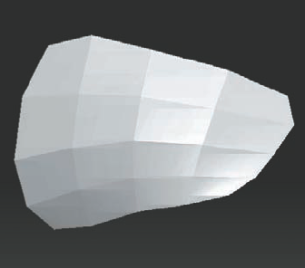
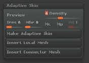
Continue drawing from one of the previously placed points. These points are actually ZSpheres. While drawing topology, click the A button to preview the mesh you are creating. Click A often so you can catch mistakes early (Figure 7.31). The A button is the same adaptive skin preview used in ZSphere modeling. You can adjust the resolution of the preview mesh under Tool → Adaptive Skin → Density (Figure 7.32). This will be an important setting when we are ready to project the detail from the original ZTool.
Continue to trace the PolyPaint plan layout, and check the adaptive skin preview often. The best method I have found is to draw single quads, gradually building up the surface. If you try to connect too many faces at once, you will sometimes link to the wrong ZSphere, causing problems when generating a polymesh later (Figure 7.33). You can use Move mode (the W key) to move points on the surface to even them out.
Figure 7.34 shows the completed remesh. At this point we are ready to create an adaptive skin. If you want a quad mesh without the ZTool detail, all you need to do at this point is click Tool → Adaptive Skin → Make Adaptive Skin.
For this example, you want to retain the sculpted details of the original ZTool with the new topology as level 1. To do this, choose Tool → Projection. Turn on Projection under the Tool > Projection menu, and under Tool → Adaptive Skin, raise the Density slider to 6. This represents the number of subdivision levels the resulting ZTool will have. If there are not enough, then all the detail will not be apparent.
Click the Make Adaptive Skin button. The new ZTool will generate and load into the Tool menu. Select it and save. Figure 7.35 shows the topology with detail reprojected. Notice that the color transfers as well as the sculpted details.

Figure 7.34. A completed remesh. Note that when you project the detail from the polypainted ZTool to the remeshed head the color will transfer as well. This is a valuable feature when transferring details from a finished character to a new mesh.
Note
If at any point you want to save your retopology and return to it at a later date, save it as you would any other subtool under Tool → Save As. When the tool is loaded later, draw it on the canvas and enter Edit mode. Select Tool → Topology and turn Edit Topology off, then back on. This will enable you to continue to draw and delete points on the surface.

Topology does not have to be built in ZBrush. You can import a low-polygon mesh generated in another application and use ZBrush's project feature to re-create your ZTool with the new topology. The typical workflow is to export the highest resolution of the ZTool that your modeling application can open. Using the high-res as a template on a layer, build a low-resolution envelope mesh on top (Figure 7.36). This is an ordered mesh where each point sits just outside the surface of the high-res.
We'll look at an example where we just want to change one aspect of the low-res mesh. We'll export the original level 1 topology from ZBrush and reproject it in ZBrush. This technique will work for an entire rebuild of topolopgy as well.
From the Tool menu load the original ZTool as well as the low-resolution remesh. Figure 7.37 shows the original mesh that we want to change to remove triangles and redirect edge flow, and the reworked low-res cage built in Maya.
Draw a ZSphere and enter Edit mode. From the Rigging menu, select the original ZTool.
Under the Topology menu, click the Select Topo button

Using Alt-click, delete some edges by clicking the points. These can be redrawn as desired (Figure 7.39).
When you are ready to generate a new Ztool, follow the same procedure as before: set your adaptive skin density, and turn on Projection. Then click Make Adaptive Skin to generate a new ZTool.


ZBrush offers other options for transferring sculpted detail from one mesh to another. Importing topology as shown earlier is one of the more difficult approaches. If you have a low-res mesh you want to project onto an existing ZTool and you don't need to further edit the topology, you'll find an option under the SubTool menu called Project All that makes this simple.
The ZProject brush also allows you to brush the projection effect across the surface with control over the intensity. Project All is a button in the SubTool menu that allows you to project the detail from one subtool onto another. Follow these steps to use Project All and the ZProject brush.
Load the original ZTool and the low-res mesh into ZBrush. Append the low-res as a subtool to the original high-res ZTool (Figure 7.40).
With the low-res mesh selected, subdivide as high as the original ZTool. For example, if the original sculpt was 1 million faces, you want to divide the low-res cage at least as high. Once this mesh is subdivided, click the Project All button under the SubTool menu (Figure 7.41). This will project the currently active subtool onto the other, inactive tools.
With two meshes in the same world space as we have here, it is an ideal way to transfer detail to other meshes without the complexity of topology tools. Click the Project All button and your mesh will capture the original ZTool detail. Figure 7.42 shows the new mesh. The original ZTool has been hidden for clarity.
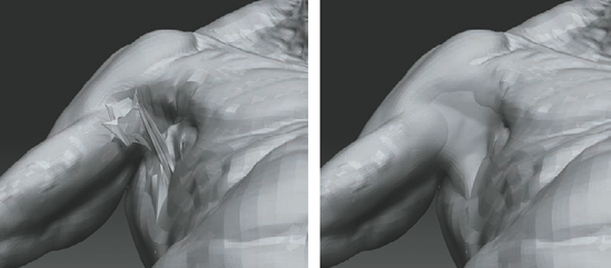
In some cases, errors will occur. Errors are especially prone to happen when the low-res mesh does not match the high-res closely enough. These are simple to fix using the ZProject brush. From the Brush menu select the ZProject brush (Figure 7.43). Make sure ZAdd is on and both subtools are visible. Make the projected mesh with the error active. Turn on transparent mode with the Transp button

Step down a subdivision level and stroke with the ZProject brush. This will have the effect of snapping the erroneous points to the surface. It is often helpful to smooth, then project and alternate between ZAdd and ZSub, depending on how deep into the mesh the points penetrate. Figure 7.44 shows the process of correcting this armpit defect. The ZProject brush works by projecting or pulling faces directly down the Z-axis, so you will need to rotate around the figure as you work, snapping the vertices to the high-res with the brush.

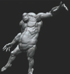
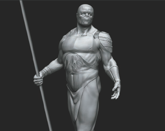
The Topology tools are often applied to 3D scan data imported into ZBrush. This could be a scan of an actor or a clay design maquette. Figure 7.45 shows a character I roughed in as a clay maquette for the Secret Level/Sega game Golden Axe.
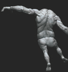
This clay maquette was photographed and scanned using a Cyberscanner 3D scan. The maquette photography was used as the basis of a Photoshop painting (Figure 7.46). The scan data was retopologized in ZBrush and used as a base to further sculpt into the final product shown in Figure 7.47.
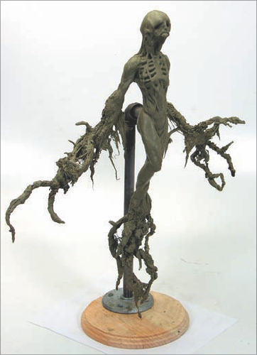
Figure 7.45. The Shade clay maquette. (Image courtesy of Secret Level /Sega and Gentle Giant Studios.)
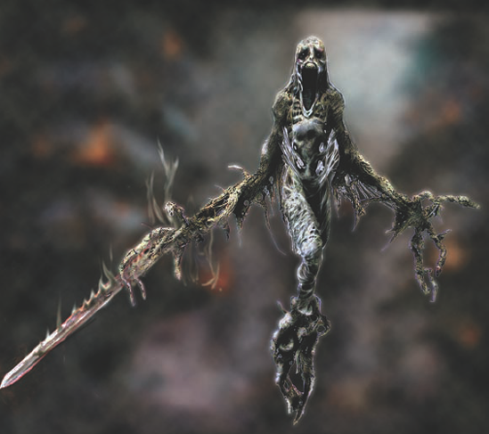
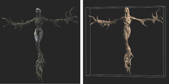
Figure 7.47. The final digital asset started in ZBrush from the scan of the clay maquette. The concept painting was projected as a color map and further refined. (Image courtesy of Secret Level/Sega, Gentle Giant Studios. Shade character by Scott Spencer and Jim McPherson.) The second image shows the initial scan data before retopology and sculpting in ZBrush.
The Topology tools can be used to rebuild existing ZTools, but they are also useful for generating entirely new subtools based on your ZBrush sculpts. By turning off the Projection option, you can build new geometry that sits perfectly against another ZTool.
Note
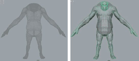
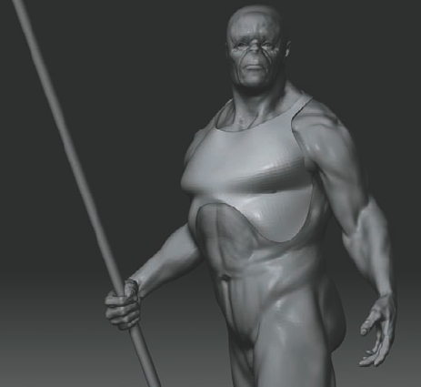
One example might be making a helmet or armor for a character by using the Topology tools to build it directly on the character. When you're building accessories with this technique, the resulting ZTool will have an ordered lower subdivision level and multiple divisions. In this section we'll build armor for a character. The ZTool used for this demo is available on the DVD as warrior.ztl (Figure 7.48).
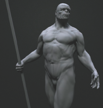
Figure 7.48. Using this ZTool from the DVD, we'll create accessories using Topology tools, mesh extraction, and ZSpheres.
Load the character ZTool into the Tool menu but don't draw it on the canvas yet. Select a ZSphere and draw it on the canvas. Enter Edit mode. Under Rigging, click the SelectMesh button and select the character ZTool (Figure 7.49). You are now ready to draw topolology, but instead of rebuilding the mesh, you want to create an accessory custom fit to the character's body. The process of drawing edges is the same, but we won't project detail from the high-res to this new topology.
Since this character was sculpted in a pose, you cannot use X Symmetry. You'll draw the outlines of the armor on both sides instead of relying on X Symmetry. If this character were in a bind pose, X Symmetry would be possible. While drawing, keep your topology all quad or triangles where necessary (Figure 7.50). Be sure to check your adaptive skin preview often by pressing the A key (Figure 7.51).
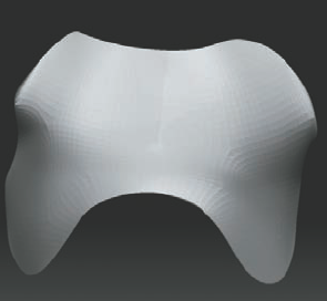
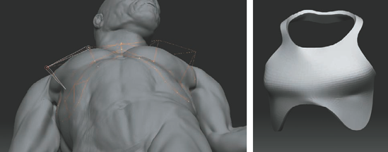
Once you've drawn the helmet mesh, switch from Draw mode to Move mode and start to move points on the surface to even out their distribution and make sure the armor looks as you want it. Continue a strip of polygons over the shoulders and the back of the neck (Figure 7.52).
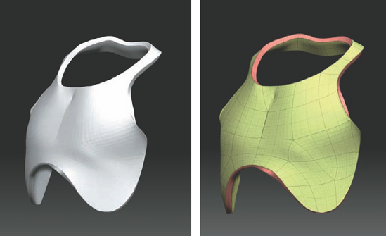
Once the topology for the chest plate is complete you will notice the mesh generated has no thickness—it is a simple polygon plane. To correct this, turn on skin thickness under Tool → Topology. This will generate a mesh with an actual thickness to it instead of a flat plane (Figure 7.53). Raise this value to .2 and preview the mesh by pressing the A key. You will see the armor how has a thickness to it (Figure 7.54). By pressing Shift+F to enter Frame mode, you will see that ZBrush automatically polygroups the front, back, and thickness of the new part separately.
Make some final tweaks to the shape of the armor. Using the Move tool, pull points away from the surface to change the shape of the armor (Figure 7.55).
When you are ready to generate a ZTool from this topology, raise the adaptive skin Density slider to 4 and click the Make Adaptive Skin button. This will create a new ZTool in the menu for the chest plate with four subdivision levels. Return to the original head character and append this part in as a subtool. It should fit perfectly and be ready for further sculpting (Figure 7.56).


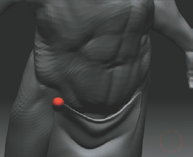
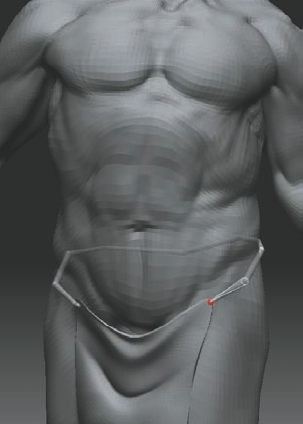
When drawing topology for drapery, you can use the same methods as you would with polygon modeling to localize details and create drapery forms. In Figure 7.57, I have isolated the forms of two folds using localized detail in the mesh. By connecting two triangles with a line of edges, I can pull the line in and create the recess of a wrinkle.

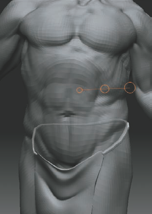
While drawing topology, you can switch to Move and increase the draw size of the brush to move multiple points together. In Figure 7.58, I am creating a sense of gravity by pulling down at the center of the folds.

Using the Topology tools to make accessories results in an ordered, multiple-subdivision-level ZTool. It can be time consuming to lay out a mesh like this, especially when you want a high level of detail in the edges of the shape you need to create. To quickly generate new subtools from an existing high-res model, you can use mesh extraction.
Mesh extraction will create new geometry based on a masked area of your tool. The higher your subdivision level, the finer the mask will appear and the better the resulting extraction will be. Extracted meshes are typically very dense and consist of only one subdivision level, so you may decide to retopologize them later in the process to create a multi level ZTool as well as mesh that can be used outside ZBrush. Extracted meshes are fantastic for quickly generating complex shapes.
In this section, you'll make a ragged shirt for this character using mesh extraction.
Select the body subtool of the character mesh. Hide all other subtools by clicking the eyeball icon next to the currently active subtool.
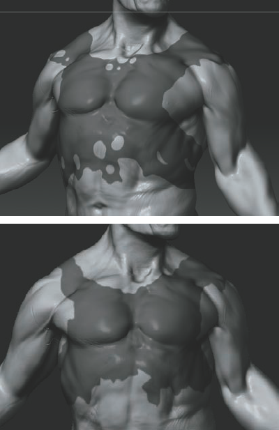
Make sure you are at the highest possible subdivision level and paint a mask for the shape you want to create (Figure 7.59).
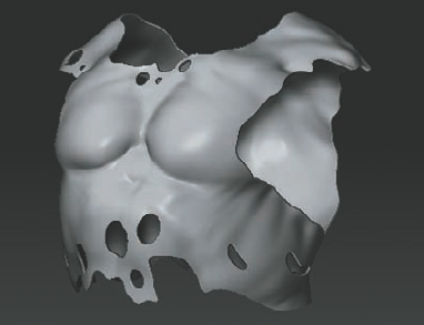
Under Tool → Subtool, you will see the Extract button (Figure 7.60). Set the thickness slider to 0.02. Leave E Smt and S Smt at the defaults; these control the resolution of the front and sides of the resulting mesh. Click the Extract button and a new subtool will be created based on the masked area (Figure 7.61). The surface can be smoothed and further sculpted.

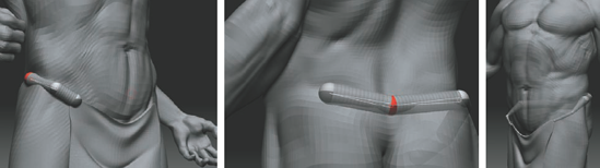
By adding a ZSphere as a subtool, you can build new geometry that fits perfectly against another model. Let's use a ZSphere chain to make a rope to hold up the loincloth.
From the Tool → Subtool → Append menu, select a ZSphere to append it into the tool as a subtool. Scale the sphere and place it to coincide with the start of the rope (Figure 7.62).
Click and drag to draw new ZSpheres. Continue the ZSphere chain around the waist (Figure 7.63).
Preview the rope mesh with the A hotkey (Figure 7.64). To move spheres out so they lie closer to the surface, turn on Transparency with the Transp button to the right of the screen. This will allow you to see the spheres through the mesh. To scale all the spheres down, select Scale or press the E hotkey and click between the first and second sphere of the chain. Figure 7.65 shows the final ZSphere chain. To create a polymesh, click Tool → Adaptive Skin → Make Adaptive Skin.
This will create a new skin subtool of the rope in the Tool menu. Append the rope into the current ZTool. You can now hide or delete the ZSphere subtool. Figure 7.66 shows the final rope.
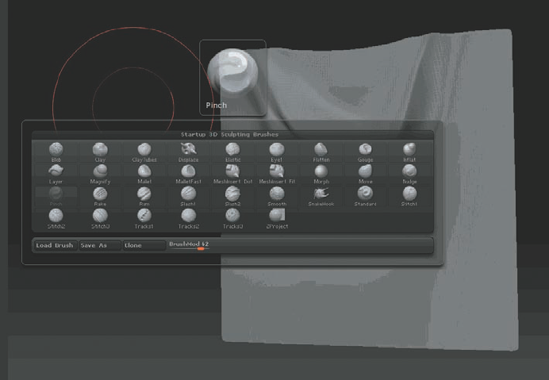
That completes the building of armor and accessories for this character. Figure 7.67 shows the final character with some additional sculpting using the Pinch brush and some alphas or texture.
These techniques can be combined with the sculpting processes we have learned so far to quickly generate complex accessories for our characters. Topology and ZSphere-based costume elements are ready for use in other 3D applications. Mesh extraction accessories, on the other hand, would require being rebuilt with the Topology tools into an ordered mesh.
Modeling Cloth: Wrinkles, Folds, and Drapery
Modeling cloth can be a time-consuming and mind-bending experience. We all know when it looks wrong, but what makes it look right?
To start, make a plane and convert to Polymesh3d (so we can freely divide it). For this experiment, I'm using a sheet draped on a rod for reference; feel free to use images, but to really get the feel for cloth, it can be useful to have some form of "life model." I always like to try new techniques on a poly plane object. It is like a blank canvas; you can learn new brush features without worrying about topology or form, so you can see how the brush reacts to your settings. I will mention some settings I like, but I strongly encourage you to tweak these or try new ways.
Once we have a draped sheet and a poly plane, I divide it by one and on my reference I find a few of the major folds, up toward the top, where the eye of the fold is. When looking at how cloth drapes over an object, you will notice that central points radiate out, where the underlying form is causing tension, thus making dramatic folds. Since this is just a quick study, I grab the top two that overlap and mask them off on our poly plane.
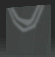
Once we have the mask, it may be a bit jagged, so I invert the selection by Ctrl-clicking off my object, and blur the mask by Ctrl-clicking on the object. Ctrl-clicking and Ctrl+Alt-clicking are great ways to sharpen or blur your selection, and by combining the two (blur a few times, sharpen a few times), you can soften your selection and get rid of the jaggedness.
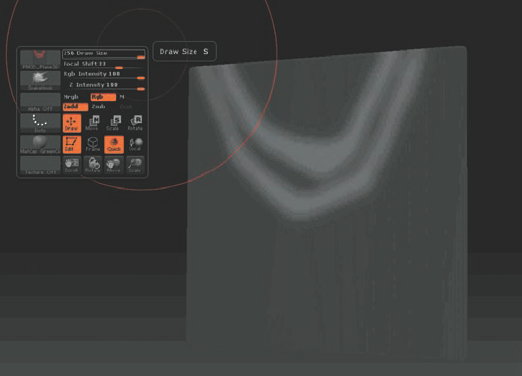
Now that we have our first main folds masked, we need to make them drape. One of the first tricks I like to do for this is while the mask is still on, go to Snake Hook mode. You could use the Move (Tweak) brush as well, but I find Snake Hook is a little more organic for our needs. But to get it to have the right feel, and by that I mean tension in the middle, we need to do a few things. First we want to crank up our brush to maximum size, and turn the focal shift to about 40–60. For even more of that tension, we could add an alpha with a soft falloff, but this will work fine for now, as we are just blocking in our shapes.
Now we simply move the two shapes down and away from our plane (toward the camera). This is not the only way to achieve this effect. We could use the new gravity functions on a Standard brush, but I like pulling the points like clay. The next thing to do is invert our selection and smooth out the edges of the pull.
That is the basic idea for our main bits of folding. Do this on a whole bunch of areas, and we'll go into a refinement stage and use a new tool, one of my favorites, the Pinch brush. The Pinch brush has a few uses in my workflow. The biggest one is using it for wrinkles and folds, and also tightening details. For this stage, we are going to use it to draw on some folds. First thing to do is change its settings. Turn the Brush mod up—something between 40 and 60 should do the trick; the next thing is to change the focal shift to something close to 70; and finally we'll add a nice soft alpha. This will make a nice pillowing effect as we draw.
When making mechanical or cloth things, I like to toggle the LazyMouse mode on and off in the Stroke settings. This tool has a few options you may want to adjust as well, mostly in the stepping area, if you are getting a "dotted" look to your strokes.
Using a combination of the mask, with the Snake Hook brush to push and pull folds and cause nice overlapping, and the Pinch brush to not only sharpen some edges but add some indentations, we begin to see the drapery we want. When using the Pinch brush, first use a low intensity, and draw along a few of our main fold lines. Holding down the Alt key, we'll cause the indentations and begin to add much more contrast to the shape of our subject.
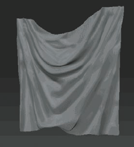
It is fairly jagged at this point, so divide one or two times and we'll do a final cleanup. This is just a rough sketch to get used to the tools—feel free to take it further than I have at this stage. At this point, follow your reference, or just have fun with it. The only two brushes I used in this whole experiment were Snake Hook and Pinch, and though it could use some refinement, I think you can see the form taking shape.
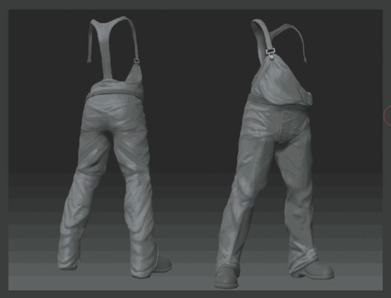
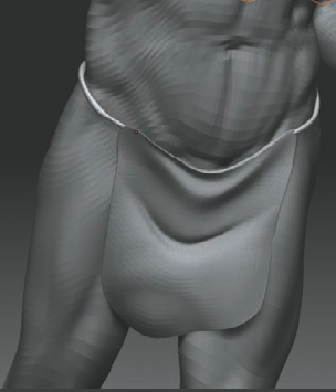
OK, those are the tools; take it further to apply this to something with some form behind it. The final image shows a pair of pants made with the same process. You'll find it's easy, just using the Move, Pinch, and Inflate tools, to create some nice wrinkle effects. When I make wrinkles, Pinch with a high falloff is my weapon of choice, but I still use the other brushes to bring out certain details as well.