

In the previous two chapters we have been working with ZBrush primitives to start our sculptures. While sculptures started from ZBrush primitives can be rebuilt into animation ready meshes using the ZBrush topology tools, in some cases you will want to start from an imported mesh instead. This may be a case where you have a generic head or body model, or perhaps an animation-ready mesh is completed and you are using this as a base. For more information on remeshing your finished sculpture to create an entirely new edge layout see Chapter 7.

In this chapter, we will import a polygon mesh from a third-party modeling package. This will be a relatively simple humanoid head mesh from the Pixologic website. This is from a selection of meshes modeled by Ang Nguyen and made available for free. In this chapter we'll create two character busts. I'll walk you through the steps involved in designing and sculpting the primary and secondary forms; we'll talk detailing in the next chapter when we cover alphas and texture stamps.
In ZBrush, models are 3D meshes that are imported into ZBrush to become ZTools. The difference between ZTools and models is that a model is just a 3D mesh file that contains polygons and UV information. A ZTool is ZBrush's native file format for sculpted objects. A ZTool can contain multiple levels of subdivision, high-resolution sculpting details, texture, and PolyPaint information, as well as alpha maps and layer data. The ZTool format allows you to store far more than just an OBJ file.
Models are imported into the tool palette where they become available with the other ZTools listed there. When importing models into the tool palette, it is important to be sure your mesh is optimized for detailing in ZBrush. If your mesh is ordered and animation ready, or is part of an existing production pipeline, you may not have the freedom to lower the initial polygon count. The edge flows and topology have already been approved for rigging and animation. When loading a model into ZBrush, it is important to understand how ZBrush determines subdivisions levels and where the system limits are.
Physical memory is the most important deciding factor in determining your highest subdivision level, followed closely by processor speed. ZBrush is not concerned with graphics cards, and multiple processors are only useful when moving the model around the screen and sculpting. ZBrush uses the amount of physical RAM installed on the system to determine the highest possible subdivision level attainable. The processor comes into play when you start to rotate and manipulate the sculpture onscreen. A faster processor will allow you to move more polygons with less lag.
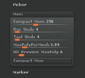
You can find the maximum subdivision level that ZBrush has set for the machine by choosing Preferences → Mem. The MaxPolyPerMesh slider will show the value in terms of millions. A value of 50 here means that ZBrush will only allow you to subdivide to 50 million polygons (Figure 3.1). As shown in Chapter 1, it is possible to raise this value, but it is not always recommended as it can cause instability. If you raise the MaxPolyPerMesh value slider, be sure to raise the CompactMem slider to 2048 or 4096. This increases the amount of memory ZBrush will use before starting to write temp files to the hard drive, which slows down performance.
The question arises of how to ensure you get the maximum subdivision levels from ZBrush. Often an artist will load a mesh for sculpting only to find that it subdivides to a level that is unsatisfactory to get the level of detail desired. Starting with a lower polygon count can help ensure you reach the highest possible subdivision level. This works because of the algorithm ZBrush uses to subdivide.
Note
ZBrush uses Catmull-Clark subdivision each time the Divide button is clicked. This means for each subdivision level, ZBrush multiplies the total polygon count by 4. So if level 1 is 4,000 faces, level 2 will be 4,000 × 4. That gives you a level 2 poly count of 16,000. If this mesh were divided again, ZBrush would multiply 16,000 by 4, giving you a level 3 polygon count of 64,000. If your initial poly count at level 1 were 17,000, you would reach 1 million faces by three subdivisions. Unless your MaxPolyPerMesh slider were set to something above 4, you would not subdivide again as the fourth subdivision level would be over 4 million.
Underlying topology can become a concern in ZBrush if your edge loops define forms that you choose to change later. There are times where your topology may fight the forms you are trying to make. Because of this, simple block models can be beneficial when working in ZBrush. They offer extremely simple bases that can be moved at the lower subdivision levels easily as well as subdivided up to millions of polygons for fine detailing. Once the sculpture is completed these meshes can easily be retopologized to any mesh resolution you desire. This helps keep the sculpting process separate from polygon modeling and allows you to focus on topology and technical concerns after the design phase is completed. The leg in Figure 3.2 illustrates how much form can be pulled from a simple block model.

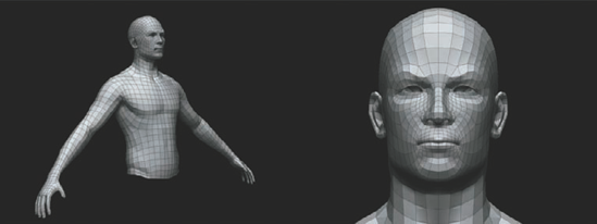
Organized meshes are models that have been specially built for animation. They have edge loops containing major muscle forms and areas of deformation (Figure 3.3). When retopologizing a design sculpt, you will strive to create an organized mesh. It is often the case that organized meshes are built before the sculpting phase. This is valid approach, but I find that it limits the sculpture and can limit the subdivision levels in some cases. Organized meshes work best for animation, while sculpting can benefit from a much simpler mesh.
Note
If you have holes in your base mesh that you want to maintain, for instance a head which is separated from a shirt, you will find smoothing in ZBrush will cause the border edges to shrink. To correct this when you import your base mesh, click Tool→ Geometry Crease button. This will tag the border edge of the geometry and keep it in place while smoothing the rest of the model.

Another option for creating meshes in ZBrush is ZSpheres. ZSpheres are a mesh generation tool in ZBrush that allow you to quickly generate models using chains of spheres and attractors (Figure 3.4). Chapter 6 will cover ZSpheres in more detail. Although ZSpheres do not offer the same direct control of edge placement that direct polygon modeling does, ZSpheres use certain controls to create form and edge loops. These controls are best suited for rapid form development and not for the creation of organized meshes. ZSpheres allow you to quickly sketch a 3D model.
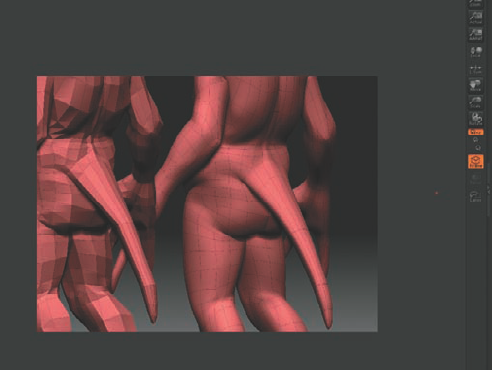
In this section we will import a simple mesh to show how a poorly distributed edge layout can create problems with sculpting. For this example I'll use the model goblin in Figure 3.5. Notice the edge distribution on this character. The goblin has a concentration on edges in the face and arms. These areas will subdivide denser than the rest of the body as you subdivide. This may be desirable in some cases, but most of the time it's best to keep an even mesh. Preplanning is key to getting a suitable mesh into ZBrush. If you can avoid topology at the outset and remesh later, I find this is the most versatile approach.
Also notice the stretched faces in his tail (Figure 3.6). Because the faces are tighter in the body and longer in the tail when subdividing, these faces will not divide as densely as other areas, making details here softer and less sharp.


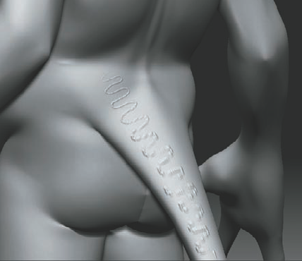
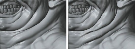
Figure 3.7 shows the underlying mesh in Frame display. Notice how the areas of tighter edges at the small of the back are denser than the tail (Figure 3.8). If I make a long curved stroke with the Standard brush, you can see the difference between the stroke at the small of the back and the faceted quality at the tail. This is because the edges are not distributed as evenly in this area due to inconsistencies in the base mesh. With higher subdivisions, this problem would be less pronounced, but whenever possible try to keep the edges evenly dispersed across the base mesh (Figure 3.9).
Note
Frame mode (Shift+F) will display the model in polyframe. This shows the current polygroups as well as the edges of the polygons. It allows you to see the edge distribution and flow as you subdivide.

Now you can see how evenly distributed edges and a low polygon count can help you get the most out of your ZBrush subdivision levels. Unless you have a specific plan for your mesh and a need to bring finished topology into the program at the outset, the best workflow is to work on a design mesh optimized for ZBrush and then use the ZBrush topology tools to generate a mesh suited to your needs—be they in games or film res models ready for animation.
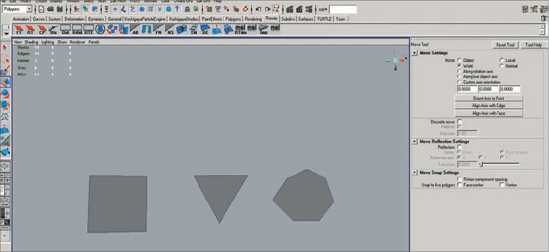
There are some problems you may encounter when using models that contain irregular topology. ZBrush prefers quad geometry or tris. A quad is a polygon face with only 4 vertices while a tri has only 3 (Figure 3.10). ZBrush will not accept n-gons, that is, a polygon with 5 or more vertices. ZBrush will triangulate these faces before importing.
Another common problem will come in star configurations (Figure 3.11) (also known as extraordinary vertices). These can sometimes pinch while sculpting and be difficult to smooth out. They will also often cause problems when rendering with a displacement map in Maya. This will usually manifest as a pinch or split in the mesh.

In some cases, you may find that you need to subdivide certain areas more than others. This could be when you are working on a character in costume whose body is not as important as, say, his head and hands. In these instances, it is good to keep your subdivisions in these areas to maximize detail instead of spreading it over the entire model. Another case may be that you have maximized your subdivisions and yet you still need more detail in a certain area of the mesh. A full subdivision level would put you over the max levels, but dividing a portion of the mesh would work. This can be accomplished with local subdivision.
To locally subdivide a mesh, follow these steps.
Load your ZTool into ZBrush, enter Edit mode with the T key, and step up to the highest subdivision level.
Mask the area you to which you want to add detail. In this case I am masking the face (Figure 3.12). Invert the mask by Ctrl-clicking on the background (off the model) or by selecting Tool → Masking and clicking the Invert button. When the area you want to subdivide is unmasked, step down to the lowest subdivision level and press Ctrl+D to subdivide.
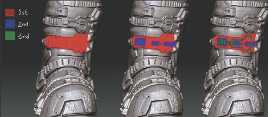
The unmasked area will subdivide. Notice the connecting region in the mesh (Figure 3.13). If you need more subdivision levels, it is a simple process to repeat. By simply Ctrl+Shift-clicking a polygrouped area, you can isolate it from the rest of the mesh mask again, invert the mask, and further subdivide by pressing Ctrl+D again until the area is dense enough for your needs. Figure 3.14 illustrates the process of local subdivision.
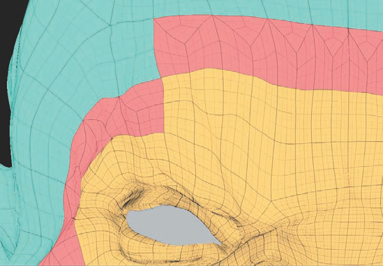
Figure 3.13. ZBrush will automatically retain a quad layout when locally subdividing. The connecting area in red represents the transition between areas of higher density and areas of lower density.

This area can now handle much higher levels of detail than other, less important areas of the character. When you locally subdivide the original mesh, the transition area and the high detail area are separately polygrouped to help you work with them.
The Making of "Elite Soldier"
I start a character by analyzing the concepts; I try to understand the character better by gathering as many references as I can possibly find. If your character has folds, then start gathering images that have leather folds in them, and so on. While making the base character here, I did not model any detail whatsoever but my focus was on the general shape.
When the base models are done, I bring all the pieces together, appending them one by one in ZBrush as subtools. Then, I start increasing the subdivision level of each subtool one at a time. The main thing here would still be shape and silhouette. The way I work, I sculpt my entire subtool simultaneously instead of finishing one subtool to the highest detail and move to the next one. That way, I could actually make much better details that flow together.

When I am satisfied with the shape and silhouette, which by now would be in Subdivision 3 in ZBrush, I start thinking about my approach for the detailing. For details such as folds, I start sculpting major folds first. At this point, references will be most important to me because I want to create a detail pass that feels natural and real. For folds, I would use just "simple brushes" with the combination of different Focus Value, Move brush, and Inflate brush a lot. Always start with a low intensity value of any brush you are using. Look for any defining folds and sculpt those in.
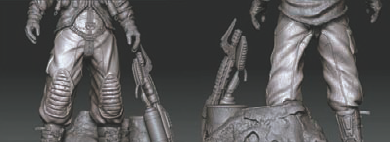
After the major folds are in, I then move to the more difficult and time consuming part, the hard body. As you can see, my character actually has a considerable amount of hard-body objects. So, before I detail any of the helmet, backpack, or boots, I have to, again, analyze the concepts. I have to figure out what will be the major details and what will be the smaller and finer detail. I think masking is an absolute must if you want to create a nice and crisp hard-body details. Let's say we are making a belt buckle: I would simply look at the general outer shape of the buckle, create a mask with that buckle shape, and then, before inflating that mask, I would actually smooth out the surface with the Smooth brush and the Flatten brush. When I am done with the masking, I then use Tool → Deformation → Inflate. (Also, I always create a new layer for any new major detail I sculpt in.)
The following image shows the steps I made for masking the boots. I always mask out the bigger areas first before masking the smaller and detail area.
Now, for the base I actually used a lot of real photo references of snow and rocks. After gathering all photos, I would then convert them into alphas in ZBrush, and just drag the alpha just like when you want to mask anything. Only this time, the mask will actually be the image you have taken earlier. Now, turn off the mask, make sure your brush has no mask too, and start sculpting the base; this way, the only geometry being affected is the ones that are unmasked. I use this method for any high-frequency details of the models, including the pants as shown. Always do high-frequency details last.
To begin, we'll import the base geometry into ZBrush as a tool. Previously we were selecting ZBrush primitives from the Tool menu. These meshes come preloaded. For the generic head, we need to import it into the program. Remember a model is an OBJ file, which is just a polygon mesh created in a polygon modeling package, it does not carry multiple subdivision levels, layers and other information. ZTools on the other hand are ZBrush models that save polygons, multiple-subdivision levels, sculpted detail, subtools, color and texture information, as well as alphas.
To import the model into ZBrush, choose Tool → Import. This will open a file browser dialog box. Browse to the Chapter 3 folder on the book's DVD and select generichead.obj. This will load the head OBJ file into ZBrush. There will be a new icon in the tool palette representing your imported model under user 3D meshes and 2.5D brushes. By default this new tool is already selected, so you may now draw it on the canvas by left-clicking and dragging into the document window (Figure 3.15).

Enter Edit mode, and you are now ready to sculpt on the model.
Note
Before we can sculpt on the tool, it must be immediately placed in Edit mode. If you were to stroke on the canvas again, it would only draw more instances of the mesh on the canvas. As soon as the tool is drawn, enter Edit mode by pressing the T key on your keyboard or by clicking the Edit button at the top of the screen.
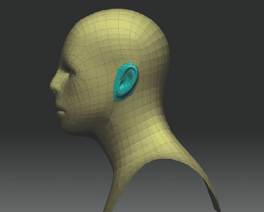
When sculpting a character, it is beneficial to have the model organized into easy-to-select parts to facilitate working on the ears or mouth separately. I want to make sure that I can isolate the ears from the head and manipulate the various parts of the ear without affecting the back of the head. The same is true for the lips. Notice that if you try to move the upper lip with the Move brush, often the lower lip will be moved too since it is in close proximity and falls under the falloff of the Move brush. Masking offers similar problems when you're trying to paint a mask on just one lip and not both.
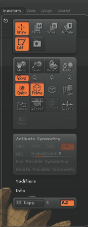
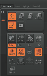
Polygroups allow you to quickly and easily isolate parts of the model for sculpting. Polygroups in ZBrush are simply selections of polygons that are tagged as being part of a group. They are similar to selection sets in Maya. Polygroups are assigned a separate color and can be viewed by entering Frame mode by pressing Shift+F or selecting the Frame button on the Transform panel (Figures 3.16 and 3.17). In Figure 3.17 this stegosaurus has its parts polygrouped into different selections.
Polygroups can help you organize parts of your model into easy-to-access groups. Having polygroups for the character's ears makes it easier to quickly show or hide the ear geometry to mask this geo independently of the head. Any polygroup can be isolated by Ctrl+Shift-clicking the group. This hides all other polygroups. You can invert this selection to show the hidden groups and hide the currently active one by Ctrl+Shift-clicking and dragging a marquee anywhere off the model on the document background. To reveal all groups again, Ctrl+Shift-click anywhere off the model on the document background.

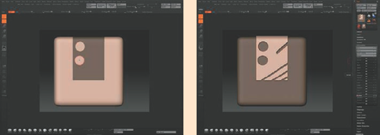
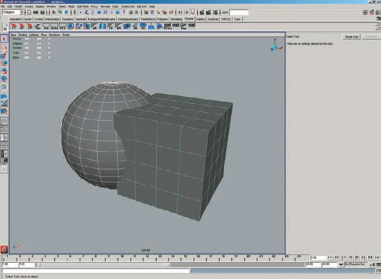
You create polygroups by choosing Tool → Polygroups. In the resulting dialog box you will find three options: Auto Groups, UV Groups, and Group Visible. Auto Groups will automatically create polygroups from separate objects in an imported OBJ file—for example, if you imported an OBJ that was a sphere and a box (Figure 3.18), ZBrush loads them as a single tool. You cannot manipulate them independently from each other. Auto Groups will automatically polygroup the two objects since the OBJ file recognizes them as separate objects even though they import as one tool (Figure 3.19).

UV Groups will create polygroups from faces arranged in the UV Texture space outside 0 to 1. Notice in Figure 3.20 that the UVs of this character are shifted outside 0 to 1. UV Groups will create new polygroups for any faces outside 0 to 1.
Group Visible will polygroup the faces visible in the document window. So if you hide part of the model and then apply Group Visible those visible faces are tagged as a new polygroup. This is the option we will use to group the ears into separate parts. It is important to note that this does not separate these faces from the mesh or change the geometry at all; it is simply a tool for quickly showing and hiding saved selections.

Note
It is possible to use the Subtool menu to break apart polygroups into separate subtools. To do this, click Tool → Subtool → Group Split. This will separate the grouped parts into different subtools. For more on subtools, see Chapter 5.
Polygroups have several functions in ZBrush. The one we will examine here is for organizing a complex mesh into easy-to-isolate parts. Notice that if I use the Move tool on the ear I pull not only the ear faces but the faces on the head behind the ear (Figure 3.21). Masking into a tight area like this can be tricky, not to mention time-consuming, if you have to repeatedly mask the ears each time you want to work around them.
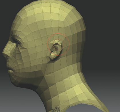
Figure 3.21. When using the Move brush on an unmasked ear, the ear as well as the faces of the head are changed.
To polygroup the ear, follow these steps:
Begin by hiding the faces using Ctrl+Shift-drag to create a hide marquee. Around the head faces, hide until just the ears are visible. Since this head is symmetrical, if you snap to a side view you can hide both sides at once.
Once the ears are visible, choose Tool → Polygroups and click Group Visible (Figure 3.22). To make hiding faces easier, you may want to turn on Lasso Select by clicking the Lasso tool button at the left side of the screen

The ear is now polygrouped. To see this, Ctrl-drag in the document window to reveal all again. Now press Shift+F to go into Frame mode and you can see the different-colored faces for the two polygroups (Figure 3.24).
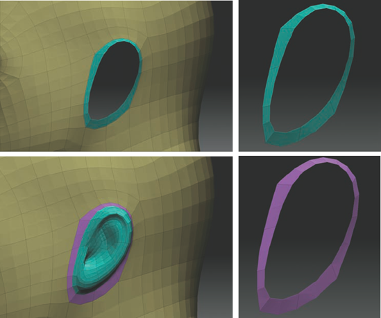
It will be useful to have the ring of faces around the ear separated from the ear and head for more flexibility when working on this area. To accomplish this, hide the faces of the head so that only the ear is visible.
Hide the ring of faces around the ear. Once the faces are hidden, you can invert what is visible on screen by Ctrl+Shift-dragging a marquee in the document window. This will show the previously hidden parts. Since the head is grouped separately from the outer ear ring, you can hide the head by Ctrl+Shift-clicking the head mesh. Now only the outer ear ring is visible. Assign this a new polygroup by choosing Tool → Polygroups → Group Visible. Figure 3.25 shows the ear and its individual polygroups.

Now you can easily mask the ear area by hiding the head using Ctrl+Shift-click. Only the head is visible; the ear is now hidden. Ctrl-click-drag a masking marquee to mask these faces (Figure 3.26). Invert the mask by Ctrl-clicking the background to keep the head masked and the ear unmasked.

By masking the ear, you can sculpt against the back of the ear, or by masking the head, you can easily modify the ear and move it without disturbing the faces of the head (Figure 3.27). This makes the process of sculpting the ears independently of the head much easier, especially since you don't have to constantly re-create a complex mask. Any time you need to mask the head, ear or outer ring, simply hide the rest of the mesh and mask the visible parts.

The same problems with sculpting the ears also manifest when you're trying to move the lips independently of one another. When trying to mask or move the upper lip, you will often find the lower lip is moved as well due to their proximity to each other. The brushes will simply affect anything underneath their falloff rings that isn't masked. The solution to this is to polygroup the lower lip separately from the rest of the head. This makes it very simple to grab one part of the mouth and quickly manipulate it while sculpting.
To polygroup the mouth, we will use steps similar to those we used with the ear, but we first need to mask the lips separately from each other. This can be difficult since the lips are so close; masking one lip invariably seems to create a mask on part of the other. We will need to spread the lips open.
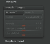
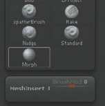
Store a morph target of your model by selecting Tool → Morph Target and clicking the StoreMT button. This creates a copy of the mesh shape in memory that we can easily return to. We are storing this morph target because we will now stretch the mouth open to facilitate masking the lips. By returning to the stored shape, we can correct any changes made to the mouth while keeping the mask.
Select the Smooth brush and smooth the mouth area. This will have the effect of spreading the mouth faces open. You can also get good results using the Inflate brush set to ZSub, as this will push faces apart (Figure 3.28).
This process is somewhat involved, so you would not want to repeat it each time you want to open the mouth. Although the mesh is masked, we can easily create a polygroup; therefore, hiding one half of the mouth is easier.
With the lower lip still masked, select Tool → Masking and click the HidePt button


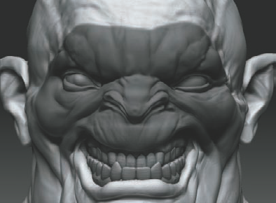
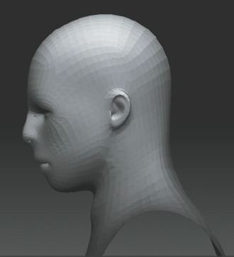
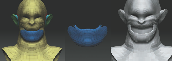
In this section, we'll sculpt a character from the generic human head bust (Figure 3.30). This ZTool is prepared with mouth and ear polygroups to facilitate a quick sculpting workflow when dealing with these areas. We'll also add new parts to the head directly using the Insert Mesh function. In the course of this demo, we'll also make use of the Gravity brush modifier as well as Transpose.

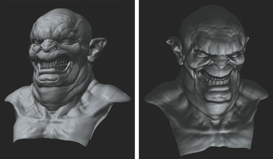
Initially we know we want this character to be leaning his head back and grinning. The orientation of the head we want is different than that of the generic head mesh. To accomplish this change, use Transpose to shift the orientation of the head on the shoulders. To do this, snap to a side view and mask the shoulders with a lasso. Switch to Transpose Move by pressing the W key and shift the head back slightly (Figure 3.31). Subdivide the mesh by pressing Ctrl+D, and using the Standard brush, build up the anatomy of the neck, at this stage just suggesting the form and direction of the sternomastoid and clavicle.
Now let's take advantage of the ear polygroups to change the ear shape. Ctrl+Shift-click the ear to hide the head. Using the Move brush, adjust the ear shape into a more monstrous form (Figure 3.32).
Using the Move brush, stretch the mouth back, starting to suggest a grin. At this stage, you can widen the neck and shoulders to give the character a more muscular look (Figure 3.33).
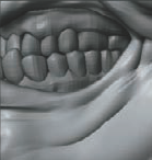
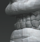
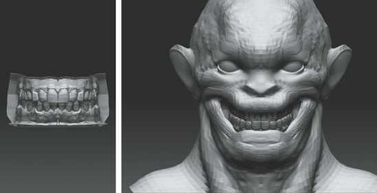
Taking advantage of the polygrouped mouth, let's open the mouth by masking and moving the shapes (Figure 3.34). At this point let's also add teeth to the model. (The teeth in this example were modeled by Jim McPherson.) Import them into the Tool palette, then append them to the model as a subtool. Using the Transpose Move and Scale options, place the teeth in the head. Notice that the teeth here are upside down—I liked the ferocity that this underbite suggested, so I left them flipped (Figure 3.35). At this stage let's also add polymesh spheres as eyeballs.
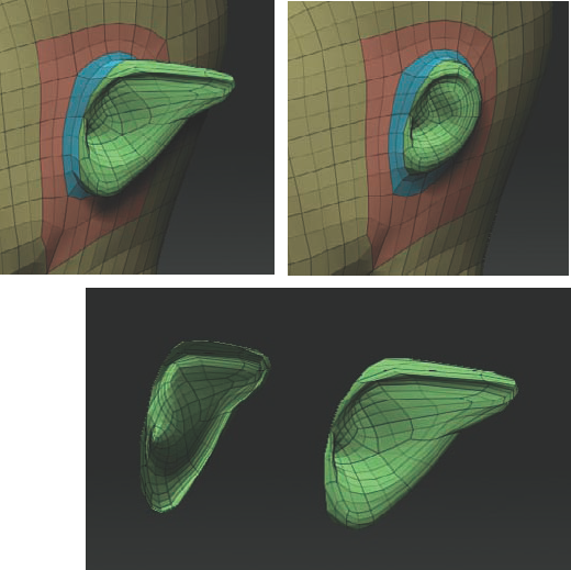
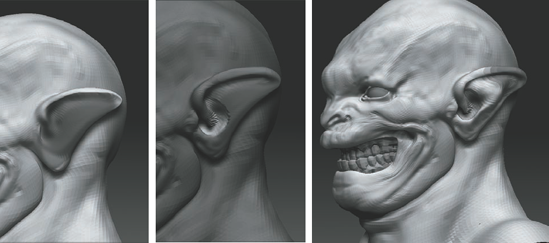
To sculpt the forms of the ear, add another subdivision level and mask out inside the helix of the ear. Invert the mask and, using the Standard brush set to ZSub, carve away the negative space and start to introduce the ear forms (Figure 3.36). Remember to address the parts of the ear as discussed in Chapter 2.
Using the Standard brush and alternating between ZAdd and ZSub, carve in the flow of major folds of flesh around the mouth and in the forehead. Take care to make the skin seem compressed at the cheeks by making deep recesses and high puckering rolls to help create the impression that the big mouth is stretching open. We can start to refine the anatomy of the neck, so also use the Interactive Light Utility

Since this character is intended to be very fat, we want to add fleshiness and folds to the cheeks and under the chin. Using the Elastic brush set to Zadd, start massing out the fat underneath the chin. Elastic is similar to Inflate, but it tries to maintain the forms already sculpted and tends to be less destructive of the area you are sculpting over (Figure 3.37).
Let's make further refinements to the shapes of the face (Figure 3.38). Use the Smooth brush on a low intensity to soften the forms. Create tight puckers between the folds of flesh by using the Inflate brush along the space where two folds meet. This has the effect of creating the look of two folds of skin pressing together.
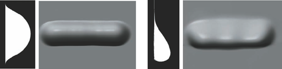
Now use the Gravity modifier on the Elastic brush to add a sense of weight to the skin folds. Gravity is acting on our bodies at all times, but it is most apparent in loose-hanging skin like this character's jowls. Figure 3.39 shows two forms. The form on the left has no sense of gravity, while the one on the right has a sense of weight and drag. By adding more body to the bottom of the fold, it appears that the fatty tissue is being pulled down by gravity. This applies to skin folds, finer wrinkles, and even cloth. The Gravity brush tries to automate this process by adding to the surface in the direction of the Gravity arrow (Figure 3.40). You can use Gravity on any brush by simply raising the Gravity slider value under the main Brush menu (Figure 3.41).
The form is nearly finished and the sculpt is showing a strong sense of character (Figure 3.42). Turn off X symmetry by pressing the X hotkey and start to "break" symmetry. Breaking symmetry means adding asymmetrical elements to different sides of the head to combat the perfect 3D look.


At this point let's add more geometry to the head. We'll add a pair of curved horns to the head. There are two approaches we can take to add geometry. The one we'll use in this section is called insertMesh. This tool allows you to insert new geometry to an existing ZTool and blend it off, just like adding clay! If the model needs to go into an animation pipeline, the resulting model can be retopologized in ZBrush to create a new ZTool with all the detail but as a single mesh.
For the horn let's use a spiral primitive. You can use any imported mesh, but the spiral is close to the shape we want so it is faster to create the horn from a ZBrush primitive. From the main Tool menu select the Spiral3D tool; draw the spiral on the canvas and enter Edit mode by pressing the T key.
Under Tool → Initialize, change the following settings to alter the shape of the horn to what we need for this character: Coverage 619, SDisp 3.10, SDivide 9.
To insert this horn ZTool into the creature ZTool it must have the same number of subdivisions. This is so ZBrush can divide and lower the meshes together and let you retain your subdivision levels after inserting new geometry. If the two tools had different numbers of levels, ZBrush could not step them back down together had you lowered subD levels. The creature head is currently five subdivision levels. With the Spiral3D tool active, click makePolymesh3D under the Tool menu
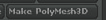
Return to the creature head by selecting it from the Tool menu. Make sure that the horn shape and the creature bust are both at their highest subdivision level—in this case, level 5. At this stage, we want to append the polymesh horn into the creature tool as a subtool, then scale and place it where we want it. Click Tool → Subtool → Append

This will add the horn as a subtool. Activate the subtool by selecting it from the subtool list (Figure 3.43). Use the Transpose Move Rotate and Scale buttons at the top of the screen to move the horn into place (Figure 3.43). Be sure to sink it slightly into the surface of the head.
We now want to clone this subtool so we can insert it into the head as a single mesh. This will allow us to blend it into the skin as a single object, something that is impossible with subtools. Under the main Tool menu, click the Clone button

If you have multiple subtools like eyes and teeth, make sure the head is selected in the Subtool menu. Open Tool → Geometry and click the InsertMesh button. This will bring up the Tool palette.
From the Tool palette select the cloned horn that you want to insert into the current ZTool. As long as both tools have the same number of subdivision levels, you can insert the horn and retain all your divisions (Figure 3.44).

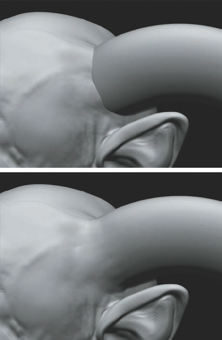
A benefit of using Mesh Insert to add geometry is that it can now be seamlessly sculpted into the other mesh. Using the Clay brush, we'll blend the horn into the character head.
Select the Clay brush from the Brush menu. Make sure the brush is set to ZAdd and the BrushMod value is set to 10 or more. Stroke along the edge where the horn intersects the head and the seam will blend away (Figure 3.45). While these two objects are not merged geometrically, simply using the ZBrush Remeshing tools can allow you to make a single ZTool from multiple inserted meshes.
Note
Using the Smooth brush across a MeshInsert seam can cause the two parts to separate. Instead of using the Smooth brush there, use the Claytubes brush with no alpha. This will have a smoothing effect on the surface while maintaining the blend. Once the seam is smooth, you can switch back to the standard Smooth brush.
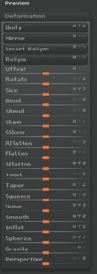
To add the second horn, simply append the horn back in as a subtool. We'll use Mirror to flip the horn, but this only works on objects with a single subdivision level. While at the highest subdivision level, click Tool → Geometry → Delete Lower to delete the lower SubD levels. With the horn subtool still selected, click Tool → Deformation → Mirror (Figure 3.46) to flip the orientation to the opposite side.
Reconstruct the subdivision levels by clicking Tool → Geometry → Reconstruct SubDiv. This button causes ZBrush to re-create each subdivision level. Click ReconstructSubDiv until you have five levels again.
Step back to the highest subdivision level and clone this mirrored horn, then delete the subtool. Then follow the same steps as earlier to MeshInsert the mirrored horn into the ZTool (Figure 3.46).
That completes the first character we'll design in this chapter. We have looked at polygrouping, creating a sense of gravity in our sculpture, introducing interactive light, and using MeshInsert. If you would like to see the entire screenshot process involved in creating this character, check the accompanying DVD. In the next section we'll create the character from the cover of this book. We'll use many similar techniques, but we'll add new geometry in a totally different way.
Note
In this section, we'll look at the steps used to sculpt the Stingerhead character from the cover of this book. I designed the Stingerhead from the same generic head mesh used in this chapter. When adding the long horn on the back of his head, I used a different technique than Insert Mesh; I used a displacement map to transfer detail. This is a valuable workflow in a production pipeline as it allows you to transfer sculpted details between meshes with different topology but similar UVs. Let's take a look at the process used to create the Stingerhead. Please see the DVD for a timelapse sculpting video of this character.
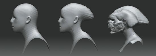
Using the Move brush, begin to pull at the mesh. Make sure that X Symmetry is turned on. At this point you are most concerned with the overall silhouette and the form of the creature. Pull at the forms of the back of the head, elongating the mesh to give the character a long spiked back to his head (Figure 3.47).
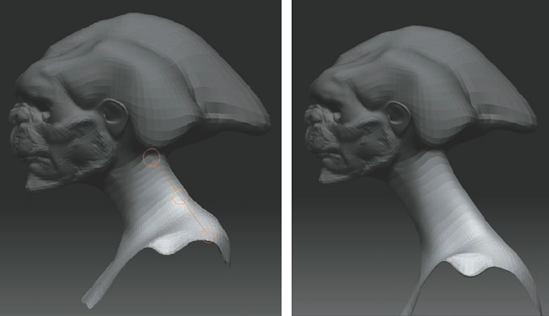
Using Transpose, lengthen the neck. You can use Transpose with masking to rotate and scale parts of a mesh rather than the mesh as a whole (Figure 3.48). Mask out the head, leaving the neck unmasked. Step up to level 3 and press the W key to enter Move mode. To soften the edges of the mask, Ctrl-click the mask a few times. This will feather the edge. Draw a transpose line from the base of the skull to the shoulders. Select the lower ring center and pull to stretch the neck out (Figure 3.49). For more information on Transpose for posing see Chapter 7.
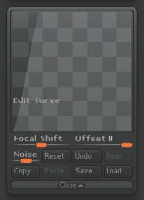
Begin to rough in the basic forms of the neck and shoulders using a custom brush I call flatInflate. This brush is available to you on the DVD. This is a variation of the Inflate brush that adds form in a flattened gradual build-up. I find it most useful when trying to subtly build up forms over the progress of a sculpture.
This brush was created and saved with the same steps detailed in Chapter 2. By altering the brush Edit curve, I was able to change the manner in which the Inflate brush affects the surface. See Figure 3.50 for a look at the Edit curve composition for the flatInflate brush.
Removing all surface shading and looking at just the silhouette allows you to concentrate on the overall silhouette of the character. The silhouette is a very important aspect of design since it is the first read, meaning the first thing your mind processes when you look at a character. Figure 3.51 shows examples of different character silhouettes and how they affect the read of the character.
A useful trick when trying to judge the overall proportions of the character is to switch from the current material to the Flat Color material. This will allow you to spot the silhouette of the character quickly as well as sculpt while looking just at the profiles (Figure 3.52). Reducing to the overall outline can help you see when a shape needs to be pushed to help communicate the feeling you are trying to inspire or depict the anatomical form you want to represent.
It is possible to snap to an orthographic view and move the mesh in Flat mode, manipulating just the overall outlines without being distracted by internal details. When you are ready to view the whole mesh again, simply select another material.
Using the flatInflate brush from the DVD, block in the clavicles, sternomastoid, and jaw muscles (Figure 3.53). These forms may be overstated now, but as the sculpt progresses they will be smoothed back and into the surface forms.
Eyeballs are added to this head just as they were in Chapter 2. Simply create a Sphere3D tool and append it into the current head.
Move and scale it to match a single eye socket. Clone this eyeball and append it back into the mesh. Be sure to clone the eyeball instead of appending the original sphere back into the tool. The reason for this is that the current eye subtool has been placed and scaled correctly. Cloning will copy this sphere's placement and allow you to simply mirror flip the copy when it is appended to the tool. Two identical eyes are now sitting on top of each other in the Subtool menu. Use the Mirror function under Tool → Deformation to flip the sphere to the other side.
A long, curved horn down the back of the head will serve our design well. However, this is difficult to do because if we want to pull the form out from the head and curve it down, it may extend the faces too far for even subdivision. This would create issues similar to the tail demonstration at the beginning of this chapter. As we saw in Chapter 2 the Reproject Higher Subdiv button sometimes corrects issues like this.


This can be accomplished with Insert Mesh as we saw in the previous demonstration or with a process I call "Displacement Map Detail Transfer." This technique uses a displacement map to transfer sculpting from one ZTool to another with an altered base mesh.
ZBrush keeps track of your sculpted detail based on vertex ID. In an OBJ file every vertex or point had a numerical ID assigned to it. This is why you can sculpt in ZBrush without UVs on your mesh. ZBrush is keeping track of your detail based on the IDs of the vertices. The problem arises when you want to add new geometry to a ZBrush tool. If you change the vertex order for any reason the mesh will "explode" when you step up subdivision levels. If you add new geometry you will not be able to re-import the mesh into the ZTool. The solution to this problem is using a method called displacement map detail transfer. Essentially we will create a displacement of our work-in-progress (WIP) mesh export and go to Maya. Add new faces, then re-import the obj to ZBrush and displace the mesh to recapture the lost details.
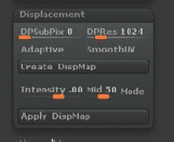
Return to the lowest subdivision level and apply AUV tiling to the mesh. AUV tiles are a ZBrush automatic UV solution and are quick and efficient. For more information on UVs in ZBrush see Chapter 5. With UVs on the mesh we can now create a displacement map to capture the sculpting work we have done so far. Go to Tool → Displacement and set Adaptive mode on and mapRes to 1024; then press Create Displacement Map. At the top of the screen a status bar will run until the map is completed. When the map is done generating it will be loaded into the alpha palette. Click on the alpha icon at the left of the screen and select the displacement map. Export it as a PSD.
Now you want to export your level 1 mesh as an OBJ file. This OBJ file we will open in Maya to add new faces and geometry. To export from ZBrush select Tool → Export and save as an OBJ file.
Now we have a displacement map that carries the details of your higher subdivision levels and a level 1 OBJ file. Notice how the level 1 mesh is so much different than the original head mesh we started with. This is because of ZBrush's Multi Resolution Editing, or MRE technology. Changes we make to the higher levels telegraph all the way down to the bottom levels.
Now we will move to Maya to add new faces and organize the mesh for re-import to ZBrush. These steps can be followed in most third-party modeling packages. Export level 1 from ZBrush as an OBJ file.
In this section we will import the mesh into Maya and extrude new faces. We will also UV the new faces and shift them outside 0 to 1 to better facilitate Polygrouping and masking in ZBrush.
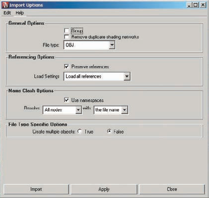
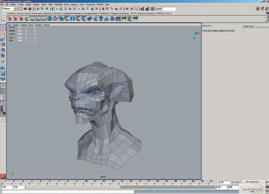
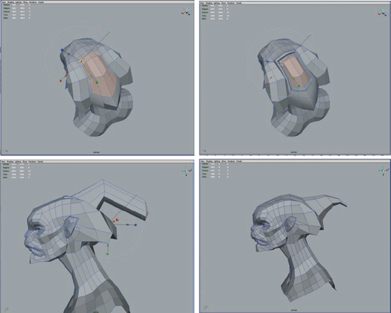
In Maya go to File → Import and select the option box (Figure 3.54). Set your file type to OBJ and make sure at the bottom of the menu Make Multiple Objects is set to false. This ensures that Maya imports the obj as one object and it also preserves the vertex order. While this is not a concern with this tutorial it is a good habit to develop since changing vertex order on meshes can cause big problems in ZBrush. See Chapters 10 and 11 for more information on moving between ZBrush and Maya. Figure 3.55 shows the mesh loaded into Maya.
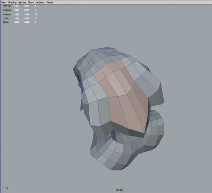
With your mesh loaded into Maya, select the faces at the back of the head you want to extrude (Figure 3.56). Using edit mesh extrude, pull a long horn out of the head and make sure to cut new edge loops so the face are evenly distributed (Figure 3.57). Don't add too much geometry here since denser lower level meshes can cause you to lose subdivision levels.
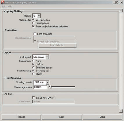
Once the faces are extruded, select all the new faces and click Create UVs Automatic Mapping to restore the default settings and apply the mapping (Figure 3.58). These do not need to be the final UVs; we are only using these texture coordinates to shift the UVs for the new geometry and polygroup the mesh later. New UVs can always be imported into ZBrush later. We want to select the UVs for the new geometry and shift them outside to the 0 to1 UV space. This allows us to use UV grouping in ZBrush to add the new faces to a polygroup and easily mask them. Go to Window → UV Texture Editor (Figure 3.59).
Here you will see the AUV tiles and your highlighted automatic mapping on the horn. If these faces are no longer selected simply reselect the new geometry. When the new faces are selected convert the selection to UV with the hotkey Ctrl+F12. With the UVs for the horn selected use the following MEL command to shift them outside 0 to 1 exactly (Figure 3.60). In the MEL window at the bottom of your screen type:
polyEditUV -u 1 -v 0;
This will shift the UVs exactly 1 unit in the U direction (across from left to right) (Figure 3.61). By preserving the UVs on the rest of the head we can use the displacement map in ZBrush to reapply details to the mesh. Return to Object mode and select the mesh. You are now ready to export it again as a new OBJ Go to File→ Export and export the mesh as an OBJ file, and then return to ZBrush.


Back in ZBrush the original head is still open. If you were to try and import the new topology back into the tool ZBrush would give you an error. Try to import the new mesh while the old ZTool is still in Edit mode. Select Tool → Import and select the new mesh. ZBrush will produce the following error:
The current mesh has a different polygon count. You can only import meshes with the same polygon count to a tool in edit mode...
This means that the new mesh has more faces and a different vertex order than the last one. ZBrush would allow us to reimport the mesh if only the UVs had changed; it would update the UVs on the ZTool and preserve all the levels of detail. This is very useful when you want to change UVs on a model after you've finished sculpting, and we will cover this more in a later chapter. Simply UV in Maya and reimport. If you preserved the vertex IDs this would go smoothly.
Because there are new faces in this case, merely reimporting is not possible. We will need to transfer details using the displacement map technique.
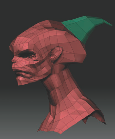
Initialize ZBrush to clear the Tool palette and remove all old maps and tools. Before you do this make sure you have exported the displacement map created earlier. Import the new geometry from Maya and enter Edit mode. Subdivide up to a higher level by pressing Ctrl+D. You want at least as many faces as the original ZTool so you can recapture the details.
When the mesh is subdivided go to Tool → Polygroups → UV Groups (Figure 3.62). This will polygroup the horn faces separate from the head since those faces are outside 0 to 1. Now we want to store a morph target. Store a morph target with Tool → Morph Target → Store Morph Target (Figure 3.63). Morph targets are copies of a current mesh stored in memory. This will allow us to return parts of the model to its original shape after the displacement.
Note
You can create morph targets by selecting Tool→ Morph Target→ Store Morph Target. Morph targets are copies of the mesh stored in memory so you can switch between a previous version of the model and an altered version. You can also use the Morph brush to alter parts of the mesh to revert back to the stored version.
In the Alpha palette import the displacement map you exported from the earlier model. With the displacement map active in the Alpha palette you can now displace the existing mesh to recapture the details of the original ZTool. Go to Tool → Displacement → and select the Mode button (Figure 3.64). This tells ZBrush to use the current alpha as a displacement map and not a bump map. Set the Intensity slider to 5 and click the Apply Displacement Map button. ZBrush will displace the mesh based on the alpha displacement map. If the effect is too weak, undo by pressing Ctrl+Z and raise the intensity value, then press Apply Displacement Map again. If the effect is too strong, undo and lower this value. See Figure 3.65. You will notice that the horn faces get noise as you displace them; this is because the map is applying to these new faces as well (Figure 3.66). By storing the morph target any artifacts can be easily removed by using the morph brush (Figure 3.67).
Go to Tool → Brush and select the Morph brush. The Morph brush blends between the current mesh and the stored morph target based on the intensity slider value. Ctrl+Shift click the horn to hide the head and set the Morph brush to 100. Brush on the surface to return the horn to its original surface smoothness.
If you find small artifacts on the face, you can remove them with the Smooth brush set to an elevation of –80
You have now added new geometry to the head and transferred you existing details to the new mesh. You'll find this technique handy if you work several hours on a model only to be asked to add new parts that could mean duplicating all your work. With this technique details can be transferred between meshes with different topologies with no problems. Save this ZTool. Now we will add some more secondary form to the model and continue to refine its character.


Next we'll continue to refine the creature head and tie together the shapes we have blocked in. For the majority of this sculpt, we're using the flatInflate, Standard, Move, and Smooth brushes. Since we have reimported the mesh, the ear polygroups are gone. You may want to re-create these before you proceed.
Use the Standard brush to create some recesses along the side horn shapes and refine the bone structure of the face. Use the Move brush to create a sweeping curve to the new stinger geometry (Figure 3.68).
Using the Move brush, add a gesture to the curve of the horn at the side of the head (Figure 3.69).
At this stage the head seems too narrow, so use the Move brush to widen the head. Also raise the crown of the head. Using a combination of the Move and flatInflate brushes, refine the area around the eyes and cheeks, trying to give more of a sense of character to the bust (Figure 3.70).
Using the flatInflate brush, build up the forms of the face. To avoid creating bloated forms, step down a subdivision level, smooth, then step back up to create more subtle shape changes. This has the effect of making the shapes at the higher subdivision level less pronounced because even though you smoothed the forms, the high level remembers the previous shape and tries to reintroduce the form. Move the light often to get a clearer picture of the shapes you are making. (I have a hotkey set for the Interactive Light utility. For more information on setting hotkeys, see Chapter 12.)
Insertions and transitions can then be picked out using the Standard brush to accentuate shadows (Figure 3.71). Use this method to refine the forms of the neck, dialing in the origins and insertions of the neck muscles, the collarbones, and the chest (Figure 3.72).
Following steps similar to those in Chapter 2, refine the ear using a combination of the flatInflate brush, Smooth, and Move. Use masking to isolate each part of the ear as you work on it. Don't forget to take advantage of the polygroup to isolate the ear from the head.
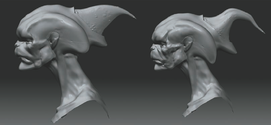
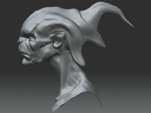
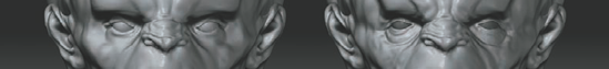
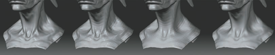

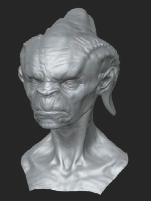
Figure 3.73 shows the final Stingerhead sculpture before fine detailing. I wanted to focus on form first since no amount of detail will help a sculpture with bad form. It is the primary and secondary shapes, the sense of bone and skin that gives a character life, not the pores and wrinkles. Those details just add even more excitement to an already successful sculpture. We'll return to this head in a later chapter to discuss high-frequency detailing and the methods used to create it.