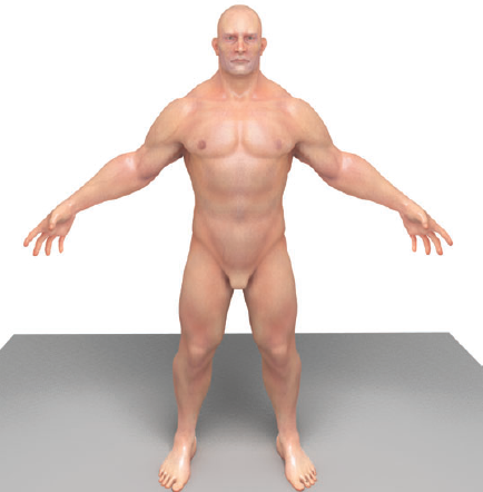
In this chapter, you'll learn techniques for creating a realistic skin texture for the male figure model using polypainting and reference imagery. Polypainting refers to the process of applying RGB values to the polygons of the model using the sculpting brushes. In essence, you are painting colors directly onto the geometry of the model. The colors you paint on the model can be converted into 2D texture maps, which are exported from ZBrush and can then be combined for rendering in a shader network and rendered in mental ray for Maya 2009. You can use these same texture maps in shader networks in similar 3D programs as well.

3D modeling and animation programs use X, Y, and Z coordinates to describe the position of a point in 3D space. Likewise, U and V coordinates are used to describe the position of a point on a 3D surface. Textures applied to a 3D model are actually 2D images wrapped across the surface of the model. By defining the U and V coordinates, you enable the software to determine how the 2D texture should be positioned on the 3D surface.
If you can imagine drawing a dot on a cardboard box and then unfolding the box and laying it out flat on the ground, you can see how the position of the dot on the unfolded box relates to the dot on the box when it is assembled into a cube (see Figure 9.1).
The first step in preparing a model for texture mapping is defining its U and V coordinates. You can then use the coordinates as a guide in a paint program to help you paint the textures so that they appear correct on the surface of the model.

U and V coordinates must be explicitly mapped for polygon and subdivision surface models; by contrast, NURBS surfaces have implicit UVs that are part of the parameterization of the surface itself. This book is concerned with polygon mesh-based characters, so we won't discuss NURBS UV coordinates. UV coordinates not only affect how textures are placed on the surface, but also determine how fur and hair behave, along with other texture-based effects such as bump and displacement maps.
The 2D arrangement of U and V texture coordinates is referred to as the UV layout. Keep several points in mind when creating a UV layout for any 3D model, including characters:
You have the choice of either letting the computer generate UV coordinates, using any of several methods of automatic UV mapping, or defining the coordinates by hand so that they are "human readable" (meaning that the shapes of the UV coordinates and the way they relate to 3D forms can easily be recognized by human artists). Humanreadable coordinates are usually preferable in most situations because they allow for easy texture editing by artists using 2D paint programs. This is very important when working in a production pipeline where teams of specialized artists divide the work of creating characters (see Figure 9.2).
Overlapping UV coordinates must be avoided at all costs; they can cause serious artifacts on the surface of the rendered model and even crash the rendering software.
Stretching, pinching, and warping of the coordinates should be kept to a minimum as much as possible.
The seams where the edges of any two sections of the layout (known as UV shells) meet should be strategically placed in areas that are less visible or follow the contours of the geometry. The seams can be noticeable in a render, and are even more so when hair and fur are applied.
There are many ways UV coordinates can be mapped for characters. Most of the time, you want to prioritize the space in your UV layout for areas of the model that will receive more detail. So the face and hands may need to use more space than the rest of the body. Typically, 25 percent of the layout is devoted to the head and hands, and the remaining 75 percent is devoted to the body; however, these proportions may differ depending on what you are trying to achieve.

Most 3D modeling and animation programs have tools that allow you to map the UV coordinates of a model. For the most part, these tools are fairly similar from one package to the next. In addition, there are stand-alone UV mapping programs, such as UVLayout by Headus, devoted to mapping UV texture coordinates quickly and easily. Pixologic's ZBrush has automatic UV mapping tools that are fairly basic but not necessarily ideal for creating UV coordinates for professional-quality models.
This chapter demonstrates how to create UV texture coordinates for the male figure model using Headus UVLayout. This chapter uses the Professional version of the program. This has a few features that are not available in the demo version, such as symmetry mode and copy-and-paste UVs; however, you should still be able to follow along using the demo version. UVLayout is fast and easy to use. Even the demo version is, in many ways, superior to the UV texture-editing tools that are part of larger 3D packages such as Autodesk's Maya. You can download UVLayout from www.uvlayout.com.
You can map the UV texture coordinates at any stage of the modeling process. You can even use polypainting techniques in ZBrush (covered later in the chapter) to paint colors on the model before creating UV coordinates. ZBrush allows you to import UV coordinates created in other programs into your model at any time, which means you have the freedom to change UV texture coordinates or even create alternate versions of the UV layout if needed.
For the sake of instruction, this chapter introduces UV layout techniques before texture painting, but keep in mind that, in practice, the order of the workflow is actually much more flexible.
When you are ready to create UV texture coordinates for your ZBrush sculpt, follow these steps:
In ZBrush, load the
textureStart.ztlZTool found in the Chapter 9 folder of the DVD. Draw the tool on the canvas, and switch to edit mode (T).Set the SDiv slider to the lowest subdivision level.
In the Tool palette, scroll down, and expand the Export subpalette.
Make sure the Qud button is on. Turn the Txr and Grp buttons off (see Figure 9.3).
When you enable the Txr button, ZBrush will include the UV coordinates as part of the exported OBJ file for the cur rent subdivision level. Since you're going to create new UVs, you don't need this button to be on now. The Grp button splits the object into sections. Always turn this button off.
The values for the Scale, X Offset, Y Offset, and Z Offset sliders have been determined so that the size and position of the model are consistent when the model is exported to another 3D program such as Maya. For the most part, you can leave these values the way they are.
Save the model as
maleFigureUVs_v01.objto a folder on your local disk. This model is also available on the DVD that accompanies this book.Close ZBrush.

In this section, you'll create the UV coordinates using UVLayout by headus. To download a version of UVLayout, visit www.uvlayout.com, and click the link that says Try. Install the program on your computer. The UVLayout demo expires after about one month, at which time you need to download and install a new version.
The standard workflow for mapping UVs in UVLayout begins by defining the shells. You do this by selecting edge paths along the surface of the object and cutting these sections off of the model. It looks as though you're breaking the model into pieces, but in reality you are just splitting the object into UV shells. As you'll see, the 3D display gives you a more intuitive sense of how the shells are defined.
Once you have split a shell from the body, you can then flatten the shell and use interactive tools to unfold the U Vs and fix any warping, stretching, or overlapping that may occur.
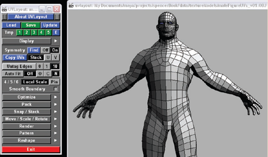
Start UVLayout. Click the Load button, and use the file browser to find the
maleFigureUVs_v01.objfile you exported from ZBrush. Once it is loaded, the figure appears in the UVLayout editor window as a 3D object. Click the Display button to expand the display options. Make sure the view mode is set to Ed (edit mode), as shown in Figure 9.4.Zoom in to the object by right-clicking and dragging in a blank part of the view. Rotate the view by dragging with the left mouse button. Zoom in to the character's left shoulder.
To define the UV shell for the left arm, you'll want to cut along the edge. To do this, hold the mouse over an edge, and press the C key. This highlights an edge path.
UVLayout automatically defines the edge path. The path stops when the software is not able to determine how to continue the path. The edge path may not follow exactly where you want to create the cut, but that's OK; it's very easy to edit the edge path. Use the W key to weld stray edges back together. Once you get the hang of it, you can precisely define the edges of the shell as you see fit. Sometimes it takes a little backand-forth between cutting and welding.
Continue creating edge paths around the left arm and under the armpit until you've defined a loop all the way around the arm.
To remove the edge paths that stray from the edge you want to cut, press the W key while holding the mouse over the stray edge paths.
Once you have defined the cutting edge, hold the mouse over the left arm, and press Enter. The arm will separate from the body (Figure 9.5).
To move the arm away from the body, hold the spacebar and middle-mouse-drag over the left arm. If the arm will not move away from the body, double-check and make sure all the edges around the arm have been cut properly using the C key.
Remember, you're not actually breaking the model apart; this is just a 3D representation of the UV shells.
Symmetry Mode
The Professional version of UVLayout has a symmetry mode, which mirrors actions from one side of the figure to the other. To activate symmetry mode, click the Find button, and then select an edge that runs along the centerline of the model. Tap the spacebar. One half of the model will turn dark gray to show that symmetry mode is enabled. Selecting, cutting, and welding edges on the brighter side will be mirrored to this dark side, and vice versa.
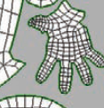
Use the same process to separate the hand from the arm.
Move the hand away from the arm. Use the C key to cut a line of edges along the front of the arm. Press Enter when you have selected a complete line of edges from the inside of the arm down to the wrist.
Use the same process to separate the top of the hand from the bottom of the hand. This will require a little more care as you define the line of edges around the perimeter of the hand.
When you are finished, you should have one shell for the arm and two for the hand (Figure 9.6). At this point, you are ready to drop these shells so that they can be edited in UV mode. Hold the mouse over each shell, and press D. The shells will disappear from the 3D view. That's OK; they are just being dropped to UV mode.
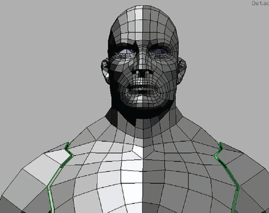
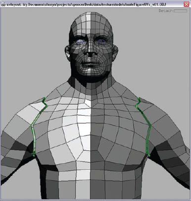
Continue the process to create shells for the other arm, each leg, each foot, the front of the torso, the back of the torso, the neck, the face, and the back of the head, as shown in Figure 9.7.
Drop each piece by pressing D while holding the cursor over each shell. When all shells are dropped, the software will automatically switch to UV edit mode.
You'll see the figure again with green lines outlining the shells. To switch to UV edit mode, click UV under the display settings.


Editing UVs involves flattening each shell, moving UV points to prevent overlapping, and arranging the shells in such a way as to optimize texture space.
To flatten a shell, hold the cursor over the shell, and hold the F hotkey. The shell will start to distort as the software attempts to flatten the 3D geometry into 2D texture coordinates. As the shell is flattened, you'll see the polygons change color. The color feedback indicates stretching or warping that will appear in the UVs. You want the shells to be as light green as possible. Blue and red areas indicate overlapping or warped UVs (see Figure 9.8). Try to reduce these colored areas as much as possible.
In the UV editor, you can use the following mouse and keyboard actions:
Select a shell by clicking it.
Move the shell by holding the spacebar and middle-mousedragging.
Rotate the shell by holding the spacebar while left-clicking and dragging.
Scale the shell by holding the spacebar, right-clicking, and dragging.
To move an individual UV, select the shell, hold the Ctrl key, and middle-mouse-drag the UV.
Cut an edge using the C hotkey.
Weld an edge using the W hotkey.
Many more functions are described in the help files. Click About UVLayout in the UVLayout control panel to open the documentation.
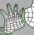
Once you have flattened your UV shells, in the Professional version of UVLayout, you can use the Optimize menu's Overlap option to finalize the flattening of the shells. The Overlap feature will find and highlight any overlapping UVs in the layout. To run it, expand the Optimize menu, and click Overlap. When you discover overlapping UVs, you can fix them by holding the Ctrl key while middle-mouse-dragging individual UV points so that they no longer overlap. Parts of the mesh such as the toes and ears are prone to overlapping UVs (see Figure 9.9).

Figure 9.8. Shells are flattened in the UV editor. The color feedback tells you whether the coordinates are warped or stretched. Ideally you want the shells to all be light green.

Figure 9.9. The Professional version of UVLayout can find and highlight overlapping UVs. Some of the overlaps are found in the ear.
If you are using the demo version of UVLayout, the Overlap feature is not available. In this case, take the time to inspect your UV coordinates carefully for any overlaps. Taking the time to do this now will save you the trouble of having to re-create the UV texture coordinates later. The demo version allows you to export UV coordinates with the model when you are done; but if you import the model again to make adjustments, the coordinates are deleted, and you'll need to go through the entire process again.
The final step in the process is arranging the UVs within the square space of the UV. UVLayout will automatically pack the UV shells for you using the controls in the Pack menu. You can choose to allow UVLayout to automatically rotate the shells to optimize the texture space. Figure 9.10 shows one such arrangement. Before packing the shells, I scaled the head and hands up somewhat so that more texture space is devoted to these parts of the body.
Click the Save button, and save the model as maleFigureUVs_v02.OBJ. You can find a version of the model in the Chapter 9 folder of the DVD.
The Save feature on the demo version exports the model with UVs. This means you can actually import the UVs created in the demo version in ZBrush. However, if you try to reopen the model in UVLayout, the UV coordinates will be automatically removed. This is to encourage you to buy the Student, Hobbyist, or Professional versions of the software. In either case, you can also use the maleFigureUVs_v02.OBJ file in the Chapter 9 folder of the DVD to continue the exercise.

The UV coordinates created in UVLayout (or any other 3D application) can be imported into the ZBrush tool at any time. To do this, take the following steps:
Open ZBrush. Load the
textureStart.ztltool found in the Chapter 9 folder of the DVD into ZBrush. Draw the tool on the canvas, and switch to edit mode.Set the SDiv level in the Geometry subpalette of the tool palette to level 1.
Expand the Morph target subpalette. Delete any existing morph targets, and store a new morph target.
Click the Import button at the top of the Tool palette. Find the
maleFigureUVs_v02. OBJ file created in the previous section (there is a version in the Chapter 9 folder of the DVD as well), and load it into ZBrush.You will not notice any immediate change to the model.
To verify that the UVs were imported into the model, expand the Texture Map section, and click New From UV Map or New From UV Check, as shown in Figure 9.11. These buttons will create texture maps based on the imported UVs. You can see the arrangement of UVs by hovering the cursor over the texture swatch; note that ZBrush UV coordinates are upside down relative to UVLayout (and Maya's coordinates). This is not a problem and is easily corrected when the final texture maps are exported from ZBrush.
UV Check
The New From UV Check button creates a texture map that diagnoses any potential problems with the UV coordinates such as overlapping. If the texture is completely gray, there are no problems with the UVs. If there are areas that appear bright red, as shown here, you'll need to fix and reimport the UVs. If your model does not have any UV coordinates, it may disappear from the canvas when you use the New From UV Check button.

After checking the UV map, it's a good idea to switch to one of the higher SDiv levels to make sure the import process was successful and the model has retained the proper detail at the higher SDiv levels.
The colors in the texture map give you a visual indication of how the UVs are laid out on the model. You can compare the colors of the texture with the colors on the 3D tool to get an idea of how one relates to the other.
Save the tool as maleFigureUVs.ztl. You can find a version of the tool in the Chapter 9 folder on the DVD.

To achieve truly realistic-looking skin in a render, it is important to think in terms of layers. Human skin is made up of layers of tissue that cover muscle, bone, blood vessels, and organs. The way in which light interacts with these layers of skin is what gives skin its unique appearance. Light is both absorbed and reflected by skin in a special way.
In general terms, when photons of light come in contact with skin, they penetrate the outermost layers of the skin, bounce around within the structure of the tissue, and are then reflected back into the environment. Warm colors such as red and orange are absorbed more deeply into the skin because their wavelengths are longer. Cooler colors such as blue and green have shorter wavelengths and are reflected back into the environment for the most part. Subsurface scattering is a term used to describe the effect created when light bounces around within a material such as skin. This subsurface-scattering phenomenon is what gives skin its translucent quality.
An obvious example of this phenomenon is the way in which the skin on the ear appears to glow reddish orange when there is a bright light behind it. Subsurface scattering is actually present under all lighting conditions and can be quite subtle.
If your goal is to render a realistic skin texture for a character in a 3D package such as Maya (using mental ray), it is important to create texture maps that work well with the special subsurface-scattering shaders used by mental ray.
This chapter is not about rendering with mental ray per se, but it's important to understand a little bit about how a typical subsurface-scattering shader works when you paint texture maps in ZBrush. You'll create three texture maps to create the color of the skin. These maps can be exported and used as layers in a shader in your 3D package of choice. Over the course of painting these maps, you'll explore a few of the amazing texturing tools ZBrush has to offer. You are by no means limited to these techniques, of course; you can combine techniques and tools to create your own particular workflow.
Rendering realistic skin has become much easier in recent years with the development of subsurface-scattering shader techniques in most major 3D software packages. Each software package has its own way of producing the effect using physically accurate algorithms as well as convincing "cheats" that simulate subsurface scattering. When rendering with mental ray, you can take advantage of the simple skin shader that uses lightmaps to simulate the effect of subsurface scattering. In Maya, there is a specific mental ray shader you can use for skin, labeled misss_fast_skin_maya (misss stands for Mental Images Subsurface Scattering Shader).
You don't need to be an expert in writing mental ray shaders to create realistic skin for your character, but when you are preparing to paint a realistic skin texture map for a figure, it's important to understand a little about how the misss_fast_skin_maya shader works. Rather than just paint a single texture that has a skin color, moles, freckles, veins, and so on, as if it were a single coat of paint, you'll actually be painting three color maps, which will be combined in the shader to create the look of skin and its behavior when it reacts to light. In the misss_fast_skin_maya shader, the three color maps are connected to the epidermal, subdermal, and back scatter color channels (see Figure 9.12).
By default the shader uses colors for each channel to simulate the skin. To achieve truly realistic skin, you connect texture maps to each channel. The texture maps you paint on the model in ZBrush are connected to the subsurface-scattering layers of the shader. Figure 9.13 shows a simple sphere, rendered in Maya using mental ray. Three color maps have been painted and connected to the misss_fast_skin_maya shader, which is applied to the sphere. Specular and bump maps are also used to simulate the texture of the skin. By themselves, the color maps do not look like skin, but when they are combined and carefully lit in Maya, the result can be very realistic.
The deepest layer in the skin shader is the back-scattering layer. This is where the skin meets muscle, fat, and bone. The colors applied to this layer are most apparent when an intense light is shining from the side of the character opposite the rendering camera.
The next layer up is the subdermal layer, where you'll find capillaries, scar tissue, and veins. If a character has a tattoo, some of the dark ink of the tattoo may be visible in this layer.
The top scattering layer is the epidermal layer. This is where you'll find moles, freckles, pores, some capillaries, embedded hairs and stubble, and the overall color of the skin. It is fairly common practice to use the same texture map for both the diffuse channel of the shader and the epidermal layer. Some artists also prefer to use a much lighter and less saturated version of the epidermal texture in the diffuse channel of the shader.

Figure 9.12. In mental ray for Maya, the misss_fast_skin shader uses three color channels to simulate the translucent quality of skin.
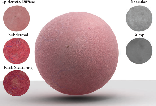
Figure 9.13. The color of the skin on the sphere is created by combining three texture maps in the fast skin shader. Bump and specular maps also help sell the look of the skin.
In addition to the three color maps used in the shader, you'll also want to paint a specular layer to control how the texture of the skin reflects the light source. The intensity of the specular map will allow the rendered skin to look wet or dry, oily or clean.
In ZBrush you'll paint a separate version of the texture map for each of the subsurface-scattering layers in the shader. Although this seems like a lot of work, the maps are similar enough that one map can serve as a starting point for the others. What may seem strange at first is that you'll be painting very colorful maps that will not look like skin until they are combined in the final shader.
The back-scattering map is the deepest layer of the skin shader. It adds a quality to the skin that is subtle but missed when absent. The colors of the layer are not part of the skin but actually the color of what lies beneath the skin. The map itself does not need to be overly detailed; mostly you want to paint the model to show the muscle and fat; some hint of bone, especially on the skull; and some of the major veins and arteries.
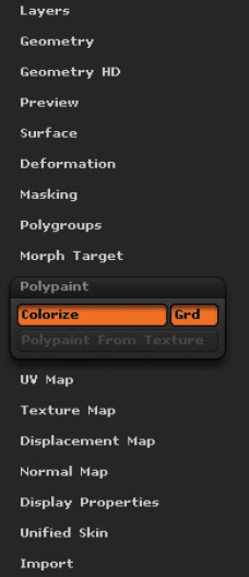
Open ZBrush, and load the
maleFigureUVs.ztlmodel on the canvas. Switch to edit mode, and set the SDiv slider to the highest level, which should be 6. In the Polypaint subpalette of the Tool palette, make sure Colorize is on so that you can paint on the model (Figure 9.14). When polypainting a model, you apply color information to each vertex of the model. The color values are blended across the polygons that share the vertices. This means that in order to create a detailed map that looks good in a final render, you need more polygons/vertices. The more you have, the better your texture's quality.Start by filling the model with a reddish orange color. Choose something close to 196, 69, 54 in the Color Chooser. In the Color palette, click the Fill Object button (make sure a gray material is applied to the model before you start painting, such as the MatCap Gray material). If white spots appear on the model when you fill it with a color, make sure no masks have been applied to the model. Expand the Masking subpalette of the Tool palette, and click Clear.
Set the current sculpting brush to Standard. You want to make sure that the brush only applies color to the model and makes no change in the geometry. To do this, make sure the Rgb button on the top shelf is on and the Zadd, ZSub, M, and Mrgb buttons are off.
Set the RGB Intensity slider to 25. Use the Standard brush to paint the model. Use a deep, dark red for areas where there are thick muscles. Use a pale yellow for areas of bone. You can paint a light pink at the tendons. At this point, you're just blocking in color. Activate Symmetry along the x-axis in the Transform palette to make the process faster.
Once you are happy with the back-scattering pass, save the tool as
maleModel_BS.ztl. You can see a version of the tool in the Chapter 9 folder on the DVD.
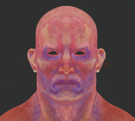
Figure 9.15 shows the model in the Flat render style so you can see just the colors of the final back scattering.

The subdermal layer lies beneath the surface of the skin. You can see a wider variety of color and detail in this layer because shorter wavelengths of light are able to penetrate to this depth. This means you can start applying cool colors such as blue and purple in some areas.
To begin the subdermal layer, you can start by painting on top of the back-scattering layer:
Load the
maleModel_BS.ztltool into ZBrush. Draw it on the canvas, and switch to edit mode.Save the model immediately as
maleModel_SD1.ztl.Set the color picker to a dull pinkish color such as 188, 109, 100. Choose the Standard brush, and set the RGB Intensity slider to 10. Make sure ZAdd, ZSub, M, and MRGB are off. Only RGB should be on.
Choose the Spray Stroke style. In the Stroke palette, set Color to 0 to eliminate the color variation in the stroke.
From the alpha library, choose Alpha 36.
Paint lightly over the model to even out the color, but try not to completely obscure the back-scattering color.
Once you have a light pink painted over the model, as shown in Figure 9.16, save the model. This light pink color will serve as the base coat for the subdermal layer.
At this point, it can be useful to start referring to a photographic reference. One of the most useful sources for photographic reference is the 3D.sk website. It was not difficult to find a reference that matched the male figure used in this chapter. Images from the Oldrich set of photographs work quite well.

Figure 9.16. To create a base coat for the subdermal layer, the back-scattering layer is lightly painted over with a pink color.
Let's start by taking a look at the torso. Figure 9.17 shows a cropped image of the torso taken from the Oldrich set from 3D.sk. You can see that the color of the skin is not completely uniform. Areas closer to the bones of the sternum are white with very subtle bluish and cool hues. Areas around the major muscle masses are warmer colors, with slight orange, yellow, and brown tints.
When you start to paint colors into the subdermal layer, make them appear exaggerated and saturated at first. This colorful layer will eventually be masked beneath addi-tional color passes, but its presence will add variation to the skin tones that will add to the realism in the final render.
Using the Spray stroke, paint a dark reddish orange on the tops of the Pectoral muscles. Use Figure 9.18 as a rough guide. Use a variety of saturated hues to break up the uniform color of the flesh.

3D.sk
3D.sk (www.3D.sk) is a family of sites devoted to offering artists a wide variety of photographic reference images. You pay a one-time fee that covers all future uses of the image. The most popular site is Human and Animal Photo References for 3D Artists and Game Developers. It's easy to see why this website is a foundation for most types of fantasy illustration of 3D artwork and a basic source for game developers.

The categories of images they provide are Modeling Photo Reference, Animation Reference Photos and Movies, Details of Eyes, and Faces.
For their regular photo sessions, they typically shoot full-body images of models in various categories of poses, including classical figure drawing, action fighting, and movement, as well as specifically requested poses. For modeling poses and details, they use diffuse lighting; for figure drawing and action poses, they prefer hard shadows.
3D.sk also offers the following specialty sites:
Female Anatomy (
http://female-anatomy-for-artist.com)Human Anatomy (
http://human-anatomy-for-artist.com)Environment Textures (
http://environment-textures.com)Reference for Comic Artists (
http://photo-reference-for-comic-artists.com)3D Tutorials (
http://free3dtutorials.com)
As you work over the other parts of the body, keep in mind that the goal here is to create variations of hue in different parts of the body. You want to end up with a very colorful paint job; this will go a long way toward adding visual interest to the look of the skin in the final shader (see Figure 9.18).

Figure 9.18. Vibrant colors are painted on the model. In the final render these colors will add subtle variations in hue.
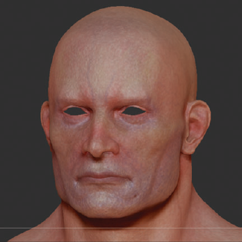
The face is where you'll find the greatest range of color. You can group the colors generally so that cooler colors follow the jawline, reds and oranges are grouped at the center of the face, and yellows are found in the upper part of the head and cranium. Within these regions you'll find pockets of other colors (see Figure 9.19). For instance, the area around the eyes may have some blues and purples, and the bony protrusions of the chin and zygomatic bones may add pale yellow.
Save the tool as maleFigure_SD2.ztl. To see a version of the model so far, open the maleFigure_SD2.ztl tool from the Chapter 9 folder on the DVD.
Once you have the color regions defined for the figure, you can break up the look of the skin and simulate the subcutaneous texture of the skin using a mottling pass.
Open the
maleFigure_SD1.ztltool. Draw it on the canvas, and switch to edit mode.Choose the Standard sculpting brush. Make sure that only the Rgb button on the top shelf is active. The Mrgb, M, Zadd, and ZSub buttons should be off.
Set the RGB Intensity to 8. Set the color to white. Choose Alpha 01 from the library. Zoom into the model, and set the draw size to around 3 or 4.
Use the Standard brush to draw a squiggly pattern all over the surface of the model. Use looping figure-eight strokes, and vary the width and size of the strokes somewhat as you go (see Figure 9.20).
For large regions of the model, use the Drag Rect stroke style with Alpha 22. Increase the Rgb Intensity to 16.
When working along the centerline of the model, turn Symmetry off to avoid creating a white stripe of overlapping strokes running down the middle of the figure.
Once the mottling pass is complete, you can paint in dark blue and red veins similar to what was created in the back-scattering pass (see Figure 9.21). Other areas of detail such as the tiny red blood vessels in the ears, the dark area of the hairline (if the character has dark hair), and the dark purple color of the lips can be painted in this pass.
Finally, to tie the colors together, set the color to a light pink such as 184, 105, 115. Set the RGB Intensity to 4, and use the Spray stroke to lightly coat the body.
Figure 9.22 shows the finished subdermal pass using the Flat-render-style material.
Save the tool as
maleFigure_SD3.ztl. To see a finished version of this tool, open themaleFigure_SD3.ztltool from the Chapter 9 folder on the DVD.


The colors of the epidermal pass most closely resemble what you see on the skin surface. To paint this pass, you can lightly cover the model with a flesh tone and then add details such as moles and freckles. This section uses a European man as an example. Other ethnicities will obviously use different hues. This layer is where the pigmentation of the skin will have the most influence on the color of the skin surface.
Load the
maleFigureSD3.ztltool into ZBrush, draw it on the canvas, and switch to edit mode.Fill the model using the MatCap_Skin04 material found in the Material Library. In the Modifiers section under the Materials palette, set Opacity to 60.
Set the color to a flesh tone such as 230, 176, 135.
Use the Standard brush with a Spray stroke and a low RGB Intensity such as 2. Make sure the Zadd, ZSub, M, and Mrgb buttons are off; only RGB should be on.
Paint over the surface of the model without completely obscuring the underlying colors.
After the model is colored with a light pink, you can dust areas with red and orange hues to help define the muscles. Use Figure 9.17, shown earlier, as a guide.
On the face, use the Spray stroke with Alpha 40 to add detail to the skin texture. Use a dark blue color around the beard area and reddish colors around the nose and eyes. By allowing the colors of the subdermal pass to show through, you already have a fair amount of subtle coloration in the skin tone.
Use a pale purplish red for the lips; try not to make the color too strong.
Finally, you can add details such as moles and freckles to increase the realism of the skin. Use a brownish color with the Spray stroke and Alpha 51 to add freckles. Moles can be drawn in by hand using the Dots stroke style and a dark brown (Figure 9.23).
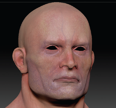
Figure 9.24 shows the final epidermal color using the Flat render style. Figure 9.25 shows the model using Preview render.
Save the model as
maleFigureED.ztl. To see a finished version of the model, load themaleFigureED.ztltool from the Chapter 9 folder of the DVD.

At this point, you'll need to convert the polypainting that you've created on the various versions of your model into textures that can be loaded into a 3D program such as Maya so they can be rendered.
Load the
maleFigureBS.ztltool into ZBrush. Draw it on the canvas, and make sure you are in edit mode. This model should have UV coordinates already. Make sure the model is at SDiv level 6.Expand the UV Map section, and click the 2048 button. This sets the size of the texture you will create from the colors painted on the model.
Make sure the RGB slider is set to 100. Expand the Texture Map section, and click the New From Polypaint button. This converts the colors into a texture map (see Figure 9.26). You'll see the texture as long as the Texture On button is active.
To export the texture, click the Clone button. This places the newly created texture in the texture inventory. You can then use the Export button in the texture inventory to save the texture to your local disk. Save the texture as a TIFF file. Name it
maleFigureBS.tif.Repeat this process for the
maleFigureSD3.ztltool and themaleFigureED.ztltool so that you end up with three texture maps for the back-scattering, subdermal, and epidermal layers.
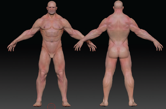
The exported textures can be brought into Maya and connected to the channels of a shader network. Figure 9.27 shows a render created in Maya using the misss_fast_skin_ maya shader and mental ray. This image was created using the textures painted in this chapter. To see how the shader was set up, open the maleFigureRender.mb scene in the Chapter 9 folder of the DVD.

Surface noise is a new feature that adds a procedural noise to the surface of a 3D polymesh tool. You can use it as a quick way to add a bumpy quality to the skin, which can then be further enhanced with the sculpting brushes.

Take the following steps to activate the surface noise feature in your figure model:
In ZBrush, load the
maleFigureED.ztltool from the Chapter 9 folder on the DVD, or continue with the model from the previous section. Make sure the SDiv slider in the Geometry palette is at the highest level.In the Morph Target subpalette, delete any existing morph targets using the DelMT button. Store a new morph target using the StoreMT button.
In the Tool palette, expand the Surface subpalette. Turn on the Noise button. The Noise button adds a procedural noise to the entire surface of the model. When you turn on the button, the bumpiness you see on the model is a preview; it actually has not changed the surface yet. Before applying the noise, you'll want to make some adjustments using the controls (see Figure 9.28).
Set the scale to 1 to make the size of the noise as small as possible.
Set the strength to –.001 to make the bumps appear as slight depressions.
The ColorBlend slider adds color to the noise. Set this value to 0.
You can fine-tune the way the noise is applied using the Edit Curve setting in the Surface section.
Once you are happy with the look of the noise, click the Apply To Mesh button to transfer the preview to the geometry of the tool (see Figure 9.29).
Use the Smooth Peaks, Morph, and Noise brushes to selectively smooth the bumpiness of the model.
You can add other details using other sculpting brushes.
The details created in the surface of the model can be converted into a normal map and exported as a texture. You can then add this to the shader network in Maya to create a more realistic skin surface.
Normal maps are a special type of bump map that use red, green, and blue colors to alter the surface normal at render time. This gives a very realistic type of bump to the surface, which renders very quickly. Creating normal maps in ZBrush 3.5 is very easy. Normal maps are calculated by comparing the lowest subdivision level with the highest subdivision level and then recording the difference as an RGB value in a texture map.
In the Geometry subpalette of the Tool palette, set the SDiv slider to 1.
Expand the Normal Map subpalette on the Tool palette. Turn on the Tangent Adaptive and SmoothUV buttons.
The Tangent button creates a tangent space normal map, which is ideal for deforming objects such as characters. In reality, many artists use tangent space maps for everything. Turn on the Adaptive and SmoothUV buttons to help optimize the quality of the map.
Click the Create Normal Map button to create the map. It will take a few minutes to generate.
To export the map, click the Clone NM button. This places a copy of the map in the texture library. From there you can click Export and save the map as
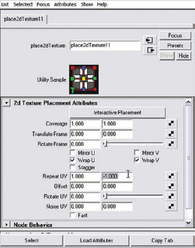
maleFigureNormal.tif.In Maya this map can be plugged into the bump map channel of the misss_fast_skin_ maya shader. Make sure to set the Use As setting in the Bump2D node to Tangent Space Normals, as shown in Figure 9.30. As with all texture maps exported from ZBrush, the UV coordinates are flipped vertically, and you need to correct this in Maya.
Select the place2DTexture node connected to the Bump2D node in the Hypershade. In the Repeat UV fields, set the second field to –1, as shown in Figure 9.31.
To see an example of the completed shading network, open the
figureRender.mbfile in the Chapter 9 folder of the DVD.