In this chapter we will create a sculpting mesh. This is a very simple blocked-in model to serve as a foundation on which to sculpt the figure. We will look at two different methods of creating a mesh upon which to sculpt our figure. The mesh we create will be a very basic armature, which represents the most basic proportions of the figure. The idea is to create the most versatile base possible to support the sculpting in subsequent chapters. By making a complex base mesh you can lock yourself into certain shapes too early. By taking the approach we use here, which creates an extremely simple blocked-in model, we will be able to sculpt nearly anything we want on the mesh. If your ultimate needs demand more specifc topology, Chapter 9 deals with rebuilding the underlying mesh while retaining all your sculpted details. This workflow of sculpting first and remeshing later is the standard approach that I have used professionally for the past several years for multiple clients.

The first section of this chapter addresses a standard polygon modeling approach to generating the mesh. This takes place in Maya and assumes a certain familiarity with Maya's modeling tool set. These tools and approaches are universal and can easily be applied to any polygon modeling package, as the tools utilized are standard between all polygon modeling applications.

The second section offers an interesting alternative to standard polygon modeling. This section is geared toward those users unfamiliar with traditional modeling or who may desire to learn a new approach. In this section we will create our base mesh using ZBrush exclusively, utilizing the mesh-generating tool known as ZSpheres.
I have included both models on the DVD, and you are welcome to skip this chapter and move on to sculpting; however, I recommend building a base mesh using these methods at least once. This is not so much for the technical experience but because this is the very first place in which we address the overall gross proportions of the human figure. In the case of this book we will be using a proportion of eight heads high. We will talk in more detail about proportions later in this chapter.
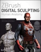
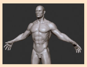
In this chapter we will look at some of the core precepts that guide me while I sculpt any human figure. Figure 1.1 shows the human figure that we will create in this book. It is a heroic male figure realized in the eight-head proportion, which we will discuss in the next section. It is my goal to share with you the work ows, thought processes, and technical approaches I take to sculpt this figure. In this first chapter we will lay the groundwork for the remainder of the book. In terms of creating the base mesh, we will discuss the ideas of gesture, form, and proportion as well as ways of thinking about sculpting in a digital environment. In terms of the tutorial itself we will be creating the very basic sculpting blocked-in mesh that will be the foundation of the next several chapters. In this first chapter we will be addressing the overall proportion of the human figure as well as starting to think about how to create a mesh that is in line with our chosen proportional canon.
When sculpting, I always try to consider three points as I work: gesture, form, and proportion. These three concepts are the foundation of my work ow. If each element is addressed in the sculpture, they combine to create a solid, effective sculpture. If any of these is omitted or addressed inadequately, the work as a whole suffers.
Let us look in depth at what these three words mean.
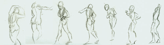
Gesture is the overall dynamic curve or action line that can be traced through a figure. Figure 1.2 shows the gesture line superimposed on a sculpture. A gesture drawing is one that does not attempt to describe the outline of the figure but the energy or direction of the action. Figure 1.3 shows an example of gesture drawings.

Gesture is just as important in sculpting as it is in drawing. A figure without a clear gesture will seem stiff and dead. Even if it is a well thought out sculpture with accurate anatomy, if there is no gesture, the sculpture will fail to excite the viewer. Gesture is apparent even in a neutral pose. The bones of the body have a gesture that telegraphs out to the final eshed figure. Without this gestural quality, characters would appear to be composed of tubes with no overall rhythm.
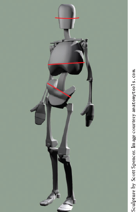
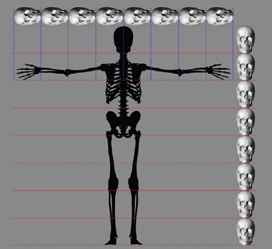
Closely linked to the idea of gesture is rhythm. Rhythm refers to the alternating curves or shapes present in the figure. Figure 1.4 shows how rhythm can be seen in the alternating masses of the head, chest, and pelvis. Notice how the masses are offset and rotated against each other to create the alternating ow of mass distribution. Figure 1.5 shows the rhythm in the curves of the skeleton. Notice how each level, from the most basic representation to the most complex, echoes the same general rhythm.
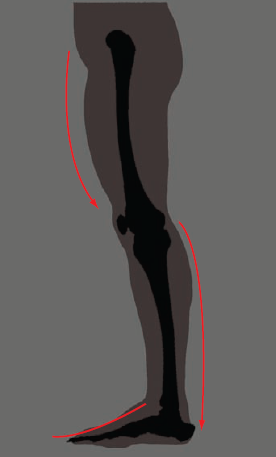
These rhythms that are present in the skeleton in uence the muscle forms and fnally telegraph out into the final eshed figure (Figure 1.6). Notice the rhythmic curves of the skeleton leg and how they are echoed in the final eshed leg in Figure 1.7.

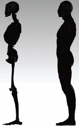
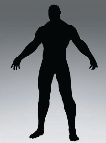
Gestural rhythms can be diffcult to spot on the fully lit figure. For this reason, in Chapter 2 you'll learn how to turn off surface shading in ZBrush and look just at the silhouette of the figure (Figure 1.8). When you look at the figure in outline, the gesture and rhythm comes into easier focus. By removing the distraction of interior forms, you can address the silhouette. This has a vast impact on the effectiveness of the rest of the figure.
Form is the external shape of an object. Form is represented by light and shadow and the gradients between. There is a hierarchy of form:
Primary form
Secondary form
Tertiary form
Throughout this book as we address different parts of the body, we will break complex shapes down into their simpler parts. By dissecting them into basic forms we render them easier to understand and reproduce. For example, let's look ahead to the rib cage. By breaking it down into a simple egg and slicing off planes, we come to the more subtle complex form of the rib cage (Figure 1.9).
This approach allows us to recognize and address changes in planes and nuances in form that we might otherwise overlook when trying to sculpt a finely detailed rib cage from the start.

The perception of form is made possible only by the use of light and shadow. Figure 1.10 shows a figure (a) with no lights and (b) with lights. Notice that when light is off there is no form, only silhouette. It is helpful to understand that when you are sculpting, you are manipulating the effects of light and shadow on a surface. This is different than painting, where you are creating light and shadow by directly applying them to the surface. Figure 1.11 shows how a shape can be changed and the resulting highlight and shadow are altered as well. This is particularly important in the final stages of a sculpture when you are refining the surface quality, the nuances of fat, muscle, skin, and bone. Often it is helpful in remaining subtle in your approach if you remember that, at this stage, you are catching light and casting shadow more than you are adding materials or carving away. Moving your light can also illustrate the transitions between forms. Figure 1.11 shows two different transitions between the same shapes. Notice the difference between them. While they may be subtle, little details like this can add up to a great character sculpture.
Because of the importance of light and shadow to the subject of form, you will want to be able to move your light as you work. There is a handy utility for this built into the ZBrush interface. This tool is found under ZPlugin>Misc Utilities and is called Interactive Light.

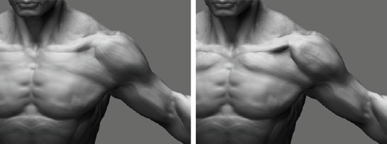
Figure 1.11. Note that the shadow in this image was darkened by adding volume to the adjoining surfaces.
The Interactive light button allows you to move the currently selected light with the mouse. Simply press the button and move the mouse, and the currently selected light will move around the sculpture. I usually set a hotkey for this tool by holding down the Control key and clicking the Interactive light button. ZBrush will ask you to assign a hotkey for the tool.
I use Interactive light often as I work, and I encourage you to do so as well. As you sculpt take time to move the light and see how different lighting conditions change your perception of the shapes you are making. By observing the highlights and shadows on the figure from different lighting conditions, you can build a more complete picture of the shape in your mind. This will be invaluable for picking out areas that may need more work, which may have been missed otherwise.
By doing this you will ensure the sculpture is accurate under all lighting conditions. Be aware that interactive light only works with the Standard Materials and will not function when using Matcap Materials.
Proportion refers to relative sizes between parts. There are several systems of proportion for dealing with the human figure. All of these systems, known as canons, strive to create a general set of rules that help create a natural-looking figure. In reality no canon of proportion is always correct for all people. The importance of the canon is that it provides the artist with a standard set of measurements to keep the figure looking natural.
View Blur
When working on the figure it can be useful to look at the surface in terms of shadow shape and value. By value, I mean the relative lightness or darkness of the shadow. When working with traditional media for centuries, artists have used the trick of squinting at the model to reduce the amount of visual information into a fuzzy generalized image. This helps you judge the shadow shapes and form. ZBrush has a feature built in to help you replicate this effect. It is called View Blur. View Blur is located under the Preferences → Draw menu. Simply set the slider to a value above 0 and press the VBlur button. This will apply a Gaussian blur to the entire canvas, helping you pick out the general shape of the forms and the patterns of highlight and shadow on the surface. With the view blurred, it is often easier to find shadows that are too dark or too hard, or areas where the highlight appears wrong. This is a telltale sign that something is wrong with the sculpture in this area.
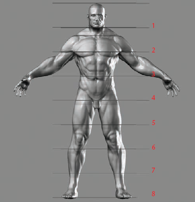
In this book we use the eight-head canon. This means we will create a figure that can be evenly divided into eight head measures in height; that is, the head is 1/8 of the total. I chose this canon for several reasons. First, it is one of the easier to remember because the head measures fall on specifc bony landmarks. Figure 1.12 illustrates another reason I chose this canon—the grace of the figure it produces. Compared to a 7 ½-head figure, the eight head model is longer and more graceful. The 7 ½-head figure, although it's more accurate, can have the appearance of being somewhat "dumpy." An eight-head figure gains length in the legs and arms and can lead to a more graceful and heroic-looking figure.
Remember that canons are sets of rules to help you create a figure that looks right; once you understand these rules you can break them. But at the outset it is important to have a set of guidelines like this to help keep the figure within acceptable ranges of proportion. This assists you in trying to fnd areas that may not be working and determine why not. Being able to refer to your canon of proportion and correct the figure based on that is a better approach than simply tugging at the overall proportion until it "looks right."
In the eight-head canon, measures fall on the following points:
Landmark | Head Measure |
|---|---|
Chin | Head 1 |
Nipples | Head 2 |
Navel | Head 3 |
Pubic bone | Head 4 |
Lower thigh | Head 5 |
Bony protrusion of the knee (Tibial tuberosity) | Head 6 |
Lower shin | Head 7 |
Bottom of feet | Head 8 |
Once your figure is established you can manipulate proportions to change the perception of the character. See Figure 1.13 for examples of how subtle changes to the figure's proportion can alter the character. Notice how simply lengthening the arms or enlarging the size of the head can vastly affect the perception of the character.

How do we apply the tenets of gesture, form, and proportion to sculpting? First we will establish the figure gesture within a set of proportions, in this case eight heads. Then we move on to each part of the body, each time readdressing the gesture, forms, and proportions of the figure in relation to the whole.
By carefully considering each as we progress through the character sculpture, we can ensure that we stay on track and sculpt with direction, not mindlessly moving digital clay in the hopes it will "look right."
In this section we will look at some of the approaches we will take in developing this character sculpture. We will look at each part of the figure, from the most basic aspects down to the more complex, sequentially creating a more and more realized form. By establishing the most basic shapes first, we will make the final figure all the more realistic, because the details live on a shape that is solid and feels accurate.
Ultimately I consider gesture the most important aspect of making a sculpture or drawing feel compelling. Without it, the figure is still and less than lifelike. Gesture is followed closely by form, the effective representation of a shape in space. Bad form creates anatomy that looks mushy and ill defined. The fnal tenet, proportion, insures that the figure looks realistic within a generally acceptable set of rules for its relative size. If you have good gesture and form but proportion is tweaked, your work will not look wrong but stylized. To create the sense of a shorter figure you may adjust the proportions of the head and hands to the body, for instance. If the gesture and form are correct, proportion is a visual guide to the size and sometimes the character of the figure.
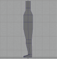
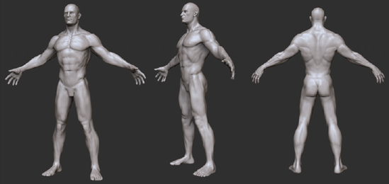
I will be using anatomical terms throughout the book where they are applicable. While it is beyond the scope of this book to offer an in-depth study of the physiology of the human body, it is important to have a basic understanding of anatomical terminology. Understanding anatomical terminology assists us in communication about the human form. By understanding what the names are and mean, we can decipher valuable information from other sources like textbooks and anatomical reference materials. Figure 1.14 shows the figure with skin and fat removed, revealing the major muscle groups we will be looking at in this book.

Understanding names also helps identify the placement and function of a part. For example, if we know that distal means distant from the centerline of the body and head refers to the end of a bone, then when we read "the distal head of the humerus," we know it refers to the end of the upper arm bone farthest from the shoulder.
Many anatomical names have Latin or Greek roots, because the earliest anatomists named them using these ancient languages. In modern times it has the added benefit that two doctors of any nationality with different languages can refer to the same part and be understood. They may look complex, but the words have very simple meanings. Once you understand these meanings you will be able to decipher a wealth of information.
The reason I give most often for why it's valuable to learn the names of parts is that it gives you a kind of mental box in which to put information about a part. If I know the name of a muscle, it is easier to remember its placement, shape, and function. Without the name of the muscle, you are dealing with a volume of information about some abstract shape. Again I should also stress that names often carry hints to placement and function in them.
There are some standard anatomical directions, movements, and regions that we will look at first. What follows is a selection of some of the more commonly encountered. These names may seem daunting at first, but just become familiar with them. You will find them used over and over when describing different muscles and bones.
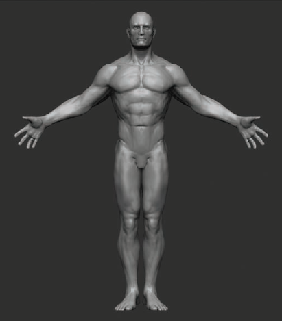
Figure 1.15 shows the human body in the default anatomical position. That is standing feet together palms out. We will sculpt our character in a more relaxed pose but it is important to understand that most anatomy books will refer to bones and muscles in this state.
When in this position anything toward the front of the body is called anterior, while anything toward the back is called posterior. The direction up is called superior, while the direction down is called inferior. Figure 1.16 shows how these and other directional terms are used in practice.
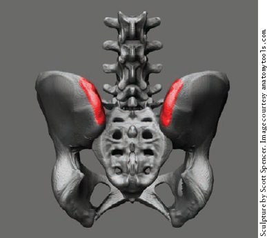
Let's look at an example of how the naming of a skeletal feature can clue us in to important information. In Figure 1.17 you see the pelvis. The marked bony landmark is an important measure on the figure; it serves as the point from which the front leg muscles radiate. It is called the iliac spine. It is more specifcally referred to as the superior anterior iliac spine. This simply means that it is the superior, toward the top, anterior, toward the front, iliac spine. Once you understand how this apparently abstruse terminology works, the inherent meaning is quite simple.
By knowing this name we can also now infer that there must be a superior posterior iliac spine as well as inferior anterior and inferior posterior iliac spines. Otherwise, there would be no need to name one "the iliac spine on top and in the front." Figure 1.18 shows the posterior superior iliac spine, which is also seen on the surface of the body making dimples at the base of the spine.


As a rule of thumb, if a landmark is defined as being superior, you can infer there is a counterpart that is inferior. The same is true of posterior and anterior. Anatomical names for the bone landmarks can also infuence the names of the associated muscles.
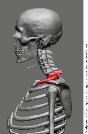
Let's look at the scapula. In Figure 1.19 you see the back of the shoulder blade—the posterior surface. The landmark marked on the image is called the spine of the scapula. This is an important landmark on the back of a eshed figure (Figure 1.20).
The muscles that lie above and below this bone feature are named Supraspinatus and Infraspinatus, respectively (Figure 1.21). The names simply mean that the Supraspinatus is superior to or above the spine of the scapula, and the Infraspinatus is inferior to or below it. Again we see how the seemingly complex naming translates into very simple terms. Once you understand anatomical direction, you find many muscle names are extremely simple to remember based on this fact.


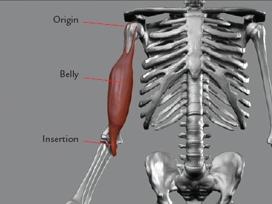
When talking about muscles we will often refer to origins and insertions, as shown in Figure 1.22.
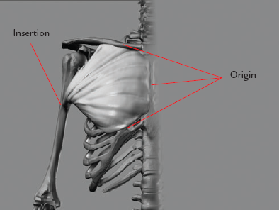
The origin of a muscle is the point at which it originates on the skeleton. Muscles pull toward their origin. An easy way to determine the origin of any muscle is to find the point at which the muscle moves the least. For example, see Figure 1.23. The Pectoralis muscle originates on the sternum and inserts on the humerus or upper arm bone. The head that attaches to the arm has the most range of motion, so it is the insertion. The shape of a muscle may change as it moves, but the origin and insertion never change; they are attached to the skeleton. So by knowing these points you understand how to place the muscle in any pose. You also know what direction the muscle pulls in and what its function is. If you know the start and end points of a muscle, deciphering its function is rather simple. Just remember that muscles pull toward the origin, and you will quickly realize the purpose of the muscle in question. Combine this with useful clues contained in the muscle name, and you have a wealth of information about the form in question.

As we discuss each part of the body in this book, we will be looking at the major muscle forms including their origins and insertions. It's important to understand what these terms mean and how they apply, so as we come across them later you will understand their importance. A simple way to remember the difference between origins and insertions is that a muscle pulls in the direction of its origin.
One last point I want to mention here about muscles. As we start sculpting, I will often refer to planes and plane breaks. This is simply a way to define a structure and apply an angular quality to the surface of the figure. For years I considered the muscles to be somewhat soft forms inside the body pressed against each other. It wasn't until I started doing cadaver dissection that it came to my attention that the muscles are very structural bodies that maintain their shapes independent of each other.
The muscles have these specifc independent shapes even to the point of having defined angles and planes. Bear this in mind as we work since you want to avoid having a soft blobby figure at all costs. As we refine the muscle forms we will continually give attention to the planes and structural quality of each. This is part and parcel of being aware of the form in our sculpture.
We are now ready to begin creating our character. To start we will block in a polygon mesh in the proper proportion. This is a very simple block mesh which will serve as a base for all our sculpting. Later in this book we will look at methods of reto-pologizing this mesh for film or games, as an animation-ready mesh. For now we are only concerned with sculpting and creating a base suitable to support the forms we want to create.
A sculpting mesh differs from an animation mesh in that the topology is not laid out for animation. Instead, a sculpt mesh features evenly spaced, effcient polygon edges that allow for consistent subdivision in ZBrush without allowing the base mesh to define any form on its own. The only aspects we want the sculpt mesh to address are gesture and proportion.
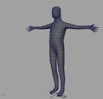
This mesh is purely for sculpting. It is not an animation-ready mesh as seen in Figure 1.24. I find that starting from the most basic mesh allows me the most freedom in sculpting. Sometimes if you have a muscle form edge looped in your base model, it can fight you as you sculpt.

Figure 1.24. An animation mesh is prepared with edge loops and topology that facilitates UV layout and animation.
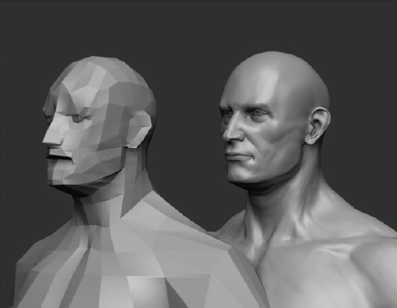
In this section we will create our simple base sculpt mesh, using very simple polygon modeling techniques that are applicable to nearly every modeling package on the market as well as Maya. This simple base mesh layout is based on a modeling approach used by Zack Petroc. I thank him for permission to reference it here. See the DVD for a video demonstration of this process. This tutorial describes the key points, but you will gain a much deeper understanding by watching the process in real time in addition to reading these steps. While I recommend following along to better understand how landmarks are placed in space, I have also included the fnal mesh on the DVD so you may move directly into sculpting in the next chapter. See Figure 1.25 for an idea of just how simple the resulting mesh will be. Figure 1.26 shows how even from a very simple base, complex shapes can be sculpted with ease.
Begin by loading your polygon modeling software. In this case we will use Maya, but the same simple steps apply to nearly all packages on the market. From the DVD load the
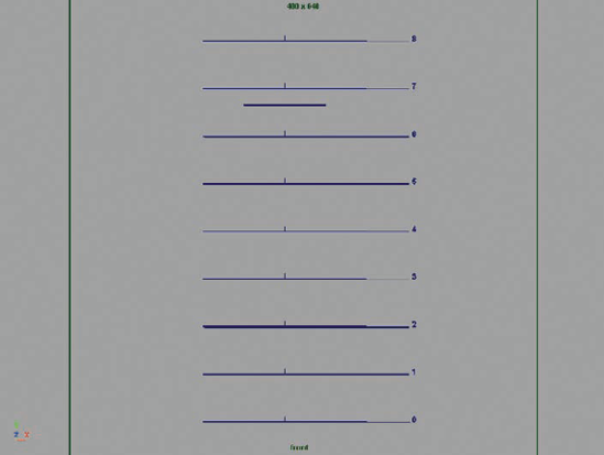
measurePlanes.obj file. This object consists of eight planes, corresponding to each head measure (Figure 1.27). This will guide us in placing major forms in the base model as well as making proportional decisions for the remainder of the project. I have added the measure planes to a layer in Maya so I can show and hide them for clarity as we work.Note
The instructions in this procedure assume that, like most ZBrush users, you're also familiar with Maya and basic polygon modeling techniques.
Save your file.
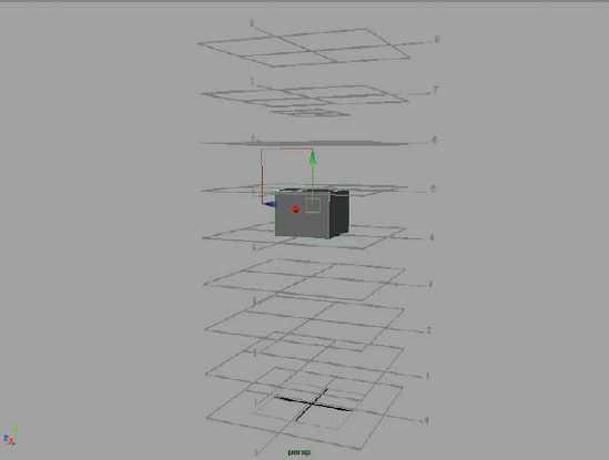
Create a polygon cube by selecting Create→Polygon Primitives→Cube. Make sure Subdivisions Width, Height, and Depth are set to 1 so each side has only one face. Move this cube up so it lies between the planes marked 4 and 5. You will need to scale it down so the top vertices lie on the line marked 5. This cube will represent the pelvis of the figure, and we will extrude all other geometry from it (Figure 1.28).
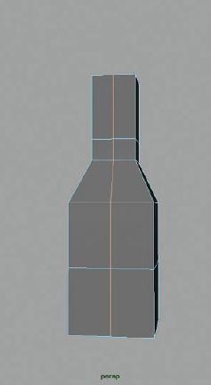
Keep the bottom of this cube aligned with the fourth head measure. This is the midline of the figure and is equivalent to the ischium or pubic bone of the skeleton (Figure 1.29). Select the top face and extrude up twice, ending at the shorter line between lines 8 and 7. This shorter line is one third of a head measure from the top. This is the highest point of the neck, on the back of the figure, corresponding to the 7th cervical vertebra and, on the front of the figure, to the first rib. These can be seen in Figure 1.30. Scale down this last extrusion. This will be the start of the neck.
As shown in Figure 1.31, extrude this face up to the bottom of the first head measure and then again to the top. This will represent the neck and head of the figure.
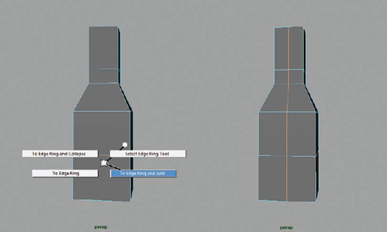
We will now cut a centerline for the body. Select one of the edges running lengthwise down the body (Figure 1.32).
Control-right-click and select Edge Ring Utilities from the Marking menu. From the second menu select To Edge Ring and Split, using the Marking menus for splitting edge rings in Maya as shown in Figure 1.33. So we can mirror the model across the middle, and cut a centerline down the model, as seen in Figure 1.34. Using the Edit Mesh → Insert Edge Loop tool, insert a loop on either side of the center edge (Figure 1.35).
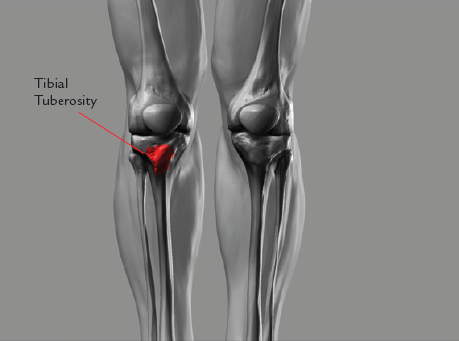
Extrude the legs down by selecting the face pictured and extrude to the ground plane (Figure 1.36(a)). Repeat the extrusion in the area pictured in Figure 1.36(b). The two edges at the knee are important. The bottom edge at the second head measure represents an anatomical landmark called the tibial tuberosity (Figure 1.37). This is the bottom-most border of the perceived structure of the knee, although it is part of the shin bone. We will talk more about the knee in Chapter 6.
At this point cut an edge along the side of the body. This will bisect the form from the side view as seen in Figure 1.38(a). Select the vertices of the leg from the knee down, and scale and move them back in the Z axis as shown in Figure 1.38(b).
To create the foot, arrange the existing edges so there are three faces toward the front of the foot, as shown in Figure 1.39(a). This configuration will allow us to extrude five toes from the minimal number of edges and is a technique I learned from Zack Petroc. Select these three faces and extrude them forward, as shown in Figure 1.39(b). See the chapter video for an in-depth look at this process.

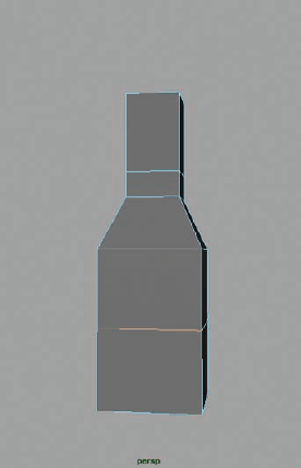


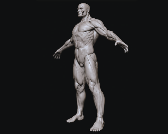
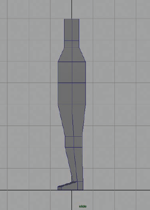
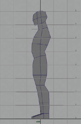
At this point we have the base geometry for the trunk and legs, but if we look at the figure in profle, you can see it is essentially a column (Figure 1.40). We will start now to edit the positions of the vertices in Z to start to suggest the profle of the figure.
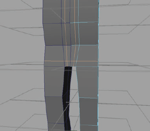
Add edge loops and move the points only in the Z direction to start shaping the body (Figure 1.41). By selecting and moving points back, we can create the taper of the legs. At this stage also note the S curves and alternating rhythms of the body, which are starting to take shape. To see this process in full, be sure to watch the accompanying DVD.
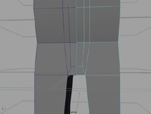
We will now add a loop in the crotch area. By adding this in the geometry it helps us define the tricky transition from the legs into the pelvis later on as we sculpt. This is the simplest approach and allows the most freedom later down the line. Cut two edges at the pelvis as seen in Figure 1.42. Delete the loops shown in Figure 1.43. Now draw a connecting edge to allow the faces at the centerline of the body to turn (Figure 1.44).
At this point, even out the edges to continue to define the volumes of the body (Figure 1.45). The idea is to use the least number of edges possible to define shapes and volumes. More edges now means fewer subdivisions later in ZBrush.
Adding the arms is as simple as selecting the face pictured in Figure 1.46. The placement of our vertices so far creates a convenient edge that will run from the bottom of the pectoral muscles in the front of the figure to the back of the armpit (also shown in Figure 1.46). We will extrude the arms out to the sides now but relax them a bit later in the sculpting phase. This will keep the figure in a "neutral pose," but also allow us to add some gesture and spring to the arms.
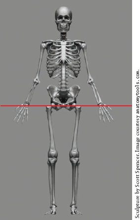
An important thing to note: The arm span on a eight-head figure is equal to the height (Figure 1.47).
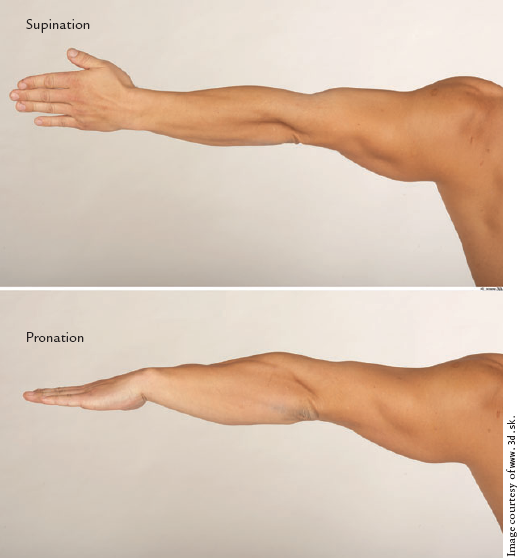
The arms are built in the anatomically neutral position knows as supination. An easy way to remember this position is the way you position your arm to hold a bowl of soup. In this position the exors and extensors of the forearm are relatively straight as opposed to their position when rotated (Figure 1.48). In this phase I extrude the fingers and toes, taking care to place edges at each knuckle. This process is best shown on screen rather than described in text. I encourage you to watch the accompanying video to see this in action.
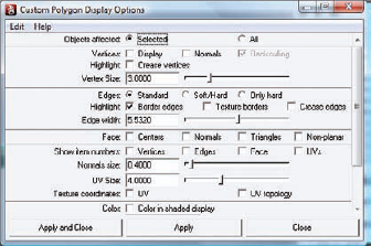
It is important to be sure the geometry is as clean as possible. If we export a mesh to ZBrush with holes or otherwise erroneous geometry that went unnoticed, it can be very diffcult to fix once we have started sculpting. Use the custom polygon display to check for border edges and unmerged polygons. In Maya click Display → Polygons → Custom Polygon Display. Make sure Border Edges is checked (Figure 1.49). This will highlight any unmerged edges or holes in the mesh.
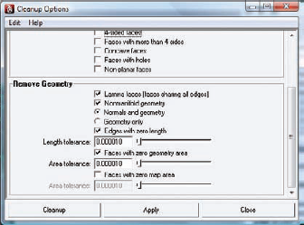
To resolve any other geometry problems, use the Cleanup function, found under the Polygons menu. Cleanup will remove lamina faces and other problematic geometry errors that may have cropped up while we model. Figure 1.50 shows the Cleanup Options window.
Now delete the instance and duplicate again as a copy. Merge the two halves and make sure all vertices along the edge are wielded. Average the vertices by going to Mesh → Average Vertices to display the window shown in Figure 1.51. This operation helps smooth the forms and soften any remaining facets.


We are now ready to export this model to ZBrush and begin sculpting.
If you would rather jump right into sculpting, I have included this base mesh on the DVD, but I highly recommend following the process of building the model at least once. At this stage you are ready to move on to Chapter 2. However, if you prefer to generate your base mesh in ZBrush, the following section illustrates this process using the ZBrush mesh-generating tool known as ZSpheres.
In this section we will look at a method of starting your sculpt mesh entirely in ZBrush using its powerful polygon model-generation tool, called the ZSphere. Instead of moving points and edges in space as one would do in Maya or other 3D applications, in ZBrush meshes are built by creating and connecting spherical volumes (Figure 1.52). For more information on ZSphere modeling please see my ZBrush Character Creation: Advanced Digital Sculpting (Sybex, 2008). ZSpheres in ZBrush 3.5 has been vastly improved from previous versions. There have been some significant changes in the way ZBrush calculates the skin from your ZSphere model. While the new version, called ZSpheres2, creates a model more accurate to the shape of your ZSphere chain, the original skinning method is still included in ZBrush 3.5 since it is still more effective for some applications like making topology loops for eyes and mouths. We will look at how to create both types of skins in this section, examining their relative strengths.
To help us place the masses and maintain accurate proportions, we will use the head measure guide ZTool included on the DVD. To load this into ZBrush, follow the demonstration video of this process, also on the DVD.

ZSpheres have the benefit of being a fast and effcient method of creating your base mesh. They are easy to create, faster than polygon modeling, and they will automatically polygroup the model into logical sections. ZSpheres are also easier to re-pose and adjust than a polygon mesh in Maya. Things like fingers and toes are far easier to create with ZSphere chains than standard polygon extrusion.
The drawback to ZSpheres is that they can be limiting when you are trying to exert more specific control over edge placement. In our example this is apparent where the legs meet the torso. In the Maya model we have the ability to create a more even transition of edges from the trunk into the legs, while the ZBrush model simply splits into two legs extruded from the body. Both will work fine for sculpting, but as you start building more characters and sculpting in ZBrush, you will discover the kind of base model you prefer to work with.
For this section we will use the head measure guide as a subtool to help us place the ZSpheres and create a figure in the correct general proportion. Each line represents a head measure on an eight-head tall figure. The first set of lines represents the head itself. Each mark down represents one more head measure. The shorter line between the first and second head measures marks the point of the shoulders on the figure.
From the Tool menu load the
measureguides.ztlZTool. We will use this model as a guide to help keep the figure's basic proportions in line. Each line represents a head measure from the foor to eight heads tall. The smaller line represents the level of the shoulders (Figure 1.53).With the tool loaded, go to Tool → Subtool and click the Append button. Select the ZSphere tool from the popup menu to append it as a subtool of the head measure guide. Make sure the ZSphere is the active subtool by clicking on it before you proceed. Also, make sure perspective is off by pressing the P hotkey. We will want to build this mesh in orthographic view.
You will now have the eight-head measure guide loaded as a ZTool with a ZSphere as a subtool.
Move the ZSphere so it lies on the 3rd head measure. You can move the ZSphere by pressing the W hotkey to enter move mode, or by selecting Move from the top of the screen. You will also want to scale the ZSphere down so it is about the size of one head unit or the spaces between the lines on the head measure guide. Scaling is preformed by selecting Scale from the top of the screen or pressing the E hotkey.
Make sure you are in draw mode by pressing the Q key or selecting Draw from the top of the screen. Press the X key to enter X symmetry mode. This will turn your cursor into two green dots. You know you are centered on the ZSphere when the two dots become one. Rotate to the bottom view of the ZSphere. You will need to enable transparency on the right side of the screen to see through the head measures to the ZSphere. As of ZBrush 3.5, you can adjust the transparency effect by going to Preferences → Draw, and turning off GhostClearTransparency. There are also several sliders here that can further refine the transparency effect to your liking. Make sure your two dots join into one on the surface of the ZSphere, and draw a new ZSphere on the bottom of the oor by click-dragging on the first sphere. If you press Shift while drawing, the sphere will become the same size as the original. Rotate to the top view and repeat the process (Figure 1.54).
Press the A key to preview the mesh. Your mesh should look like Figure 1.55. Press A again to exit preview mode, and move the bottom sphere to the 4th head measure line and the top sphere to the shoulder line as seen in Figure 1.56. If you have problems seeing the head measure lines, turn off transparency so they become opaque again.
Under Tool → Adaptive Skin, turn on Classic Skinning. Set Density to 4, Ires to 3, Mbr to 91, and Mc to On. This insures the best results from the polygon skin. Feel free to experiment with these values and use anything that you feel makes your volumes better. The important thing in this tutorial is that the proportions remain consistent.
Add child spheres for the shoulders and pelvis as seen in Figure 1.56. Be sure to check your progress with the A key. Since we are using the new ZSpheres2 skinning, by default the mesh should conform exactly to the spheres you see on screen.
Draw ZSpheres for the hands, feet, and head. Switch to move mode with the W key and pull them away from the body (Figure 1.57). Drag the foot spheres down to the 8th head measure. Drag the wrist spheres to just below the 4th head measure. Once the wrists are placed at the point just below the waist, we know the arm length is accurate. Switch to rotate mode with the R hotkey, and clicking between the shoulder and wrist spheres, rotate the arms up as seen in Figure 1.57b. This is because the arm span is equal to the total height of the figure. If we place the wrist just below the waist then rotate them up into position, we can be sure the arms are the correct length once the hands are added.
Press the A key and check your progress. Your figure should look like Figure 1.58.
Add spheres for the elbows and knees so your figure looks like Figure 1.59. Make sure to place the knee ZSphere just above the 6th head line. Scale down the wrist and ankle ZSpheres slightly to give a taper to the limb. At this stage you may want to turn off visibility on the head measure subtool so you can see the fingers and toes as you work on them. Visibility is disabled by clicking the eyeball icon next to the subtool in the Subtool menu (Figure 1.60).
Create a ZSphere chain for the foot and heel (Figure 1.61).
To add fingers, draw five small child spheres on the end of the arm as seen in Figure 1.62.
Move the thumb down and arrange the finger spheres in a natural position. Add another sphere to the end of each finger and pull them out. Remember, you can press Shift while dragging to make a new sphere the exact same size as its parent. Add a ZSphere to the wrist, and scale it down slightly so the arm tapers before the start of the hand. Press A to preview your mesh. Your hand should look like Figure 1.62b.
Repeat the same process for the toes (Figure 1.63). The shape may look strange now, but the odd forms can be corrected in seconds with the Move brush once we start sculpting. In addition it is far easier to pose and create gesture in the figures using ZSpheres than it is when extruding faces in Maya. Now we want to add the head and neck.
Restore the visibility on the measure guides. Turn on transparency, and from the top view add a neck ZSphere on the shoulders. Draw another ZSphere on the neck and move it up to the first head measure as shown in Figure 1.64.
At this stage add two ZSpheres between the head and shoulders by clicking between them. Scale these two spheres down to create a neck. Add small spheres for the eyes, nose, and mouth as seen in Figure 1.65.
These smaller spheres will create topology loops to represent the inner eyes and mouth as well as the nose and ears. If you preview this mesh, you will have something like Figure 1.66.
The effect of these spheres differs from what you can do using Classic Skinning. Under Adaptive Skin enable Classic Skinning mode, set Ires to 3 and Mbr to 9. Move the eye and mouth spheres in slightly so they become holes in the ZSphere head (Figure 1.67). Now when you preview, you will have recessed loops in the mesh for the eyes, nose, and mouth.
When adding geometry for facial features, as we have just done, this is where you must decide on which skinning method works best for you. The default skinning in ZBrush ZSpheres2 will look much closer to the ZSphere chain you create for your figure, but it will not handle the countersunk ZSpheres in a predictable manner. That is one reason why there is a Classic Skinning button under the Adaptive Skin menu. Experiment with both skinning methods. For this tutorial I used Classic Skinning with the following settings to make the edge loops for the facial features.
If you use the new ZSpheres2 skinning method, make sure you do not countersink the spheres for the facial features into the head. ZSpheres2 does not support countersink, and this may cause undesirable behavior. Figure 1.68 shows this ZSphere model under both skinning methods in ZBrush Classic and ZSpheres2. Notice that the Classic Skinning gives you more accurate facial loops for sculpting the eyes, nose, and mouth while the default ZSpheres2 skinning seen on the left follows the ZSphere chain more accurately but does not recess the topology for the face. The edge loops are still there in ZSpheres2; you will just have to manually press them into the head when you start sculpting. Both skins will work fine; it is entirely up to your own preference when working with the base mesh. Figure 1.69 shows the facial topology of Classic Skinning and ZSpheres2 so you can see how the underlying loops are conformed to the surface.
Remember, if you use Classic Skinning, the volume of the limbs will no longer follow the ZSphere chain as you have made it. To rectify this, simply add more Zspheres between the joints to help define the forms as seen in Figure 1.70. It is also important to note that the hands and feet will generate topology differently between the two skinning methods. Try both and decide which mesh is more appealing to you as a base on which to sculpt. Please see the DVD for a video demonstrating both ZSphere approaches and the nuances of each skinning method.
Save your Zsphere model by clicking Tool → Save As. make sure to save the Zsphere model as well as the Adaptive Skin separately. We will now generate a polygon mesh from the ZSphere model. Under the Adaptive Skin menu, click the Make Adaptive Skin button. You will notice a new ZTool listed in the tool menu prefixed with the name Skin. Select this tool. This is the polygon mesh generated from the ZSphere model. Save this tool separately from the ZSphere model in case you want to revisit the original ZSphere chain for further edits in the future. By using the Move brush you can quickly move the mesh into a more accurate shape of a basic human, as seen in Figure 1.71. Notice the eyes and mouth have been pressed in and the hands and feet shaped. This is done entirely with the Move brush to help refine the fgure for the next chapter. The very simple Zsphere model can quickly be refined into a more accurate human form using the Move brush alone (Figure 1.72). Please see the DVD for copies of all the ZSphere and Adaptive Skin models as well as multiple variants of the ZSphere skeleton.
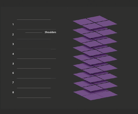

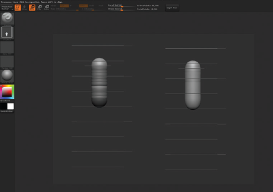
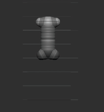
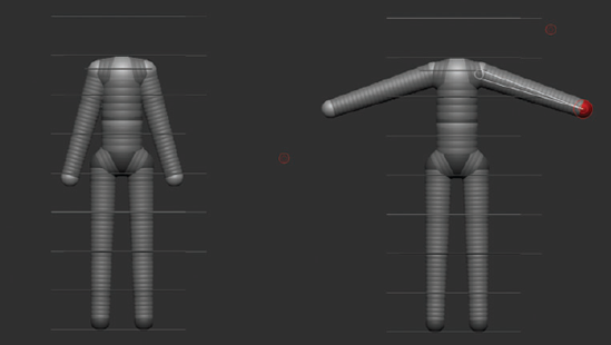

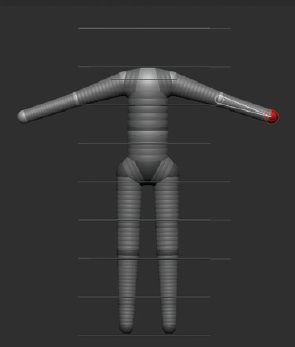


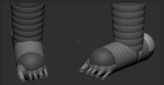


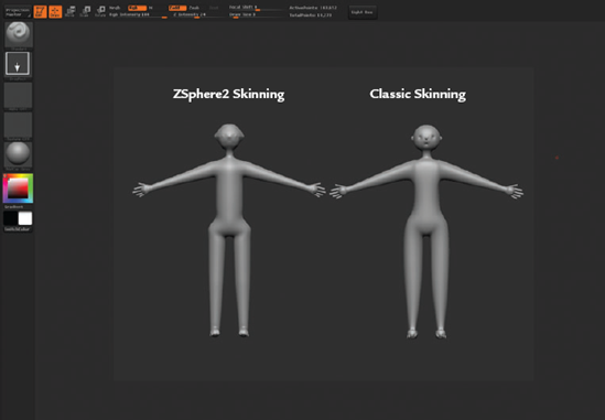

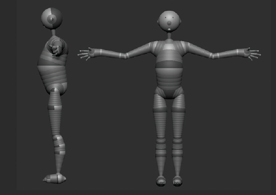
Figure 1.70. By adding more spheres to each limb, Classic Skinning can be made to more accurately represent the volumes of the figure.


Note
For more information about using ZSpheres, see ZBrush Character Creation.
See the video for this lesson on the DVD for a complete walk-through of this process. This represents the most basic form on which to start sculpting. It doesn't look special now, but it will be very useful to us since our base is built with accurate proportions in mind.
In the next chapter we will discuss sculpting silhouettes, planes, and plane breaks. By looking at the figure in terms of its external profiles, we can establish important landmarks without being distracted by too much detail too early. We can also take this opportunity to strengthen the gesture and rhythm of our figure.