
CONTENTS
17.1 Definitions and Normative Reference
17.2 Principal Measurement Methods for Straightness
17.2.1 Comparison to a Straightness Datum
17.3 Straightness Measurement Based on an Optical Beam
17.3.1 Optical Alignment Systems
17.3.3 Straightness Interferometer
17.4 Straightness Measurement Based on a Mechanical Datum
17.4.1 Error Separation by Reversal
17.5 Straightness Measurement Using Angle Instruments
17.6.1 Straightness Measurement of a Machine Axis
17.6.2 Rotational Error Measurement of a Machine Axis
17.1 DEFINITIONS AND NORMATIVE REFERENCE
There is a series of basic geometrical elements used to describe three-dimensional objects. With each of these elements of ruled geometry, a feature is associated describing the form deviation that is subject to geometrical measurements:
• Line—straightness
• Plane—flatness
• Circle—roundness
• Sphere—sphericity
• Cylinder—cylindricity
The straightness is considered to be a two-dimensional feature, that is, the deviation from a straight line confined to the two dimensions of a plane. According to ISO 12780-1 [1], the straightness profile is defined as the intersection of a nominally plane surface with the straightness plane perpendicular to the surface (Figure 17.1). The local straightness deviations are the distances of the straightness profile points to the reference line in the reference plane. The reference line may be calculated based on least squares linear regression or minimum zone criteria. The total straightness deviation STRt is the sum of the maximum local deviations from the reference line to both sides, that is, a peak to valley value:
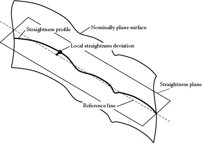
FIGURE 17.1 Definition of the straightness of a profile as the intersection of the surface and a straightness plane perpendicular to the surface.
where S(x) is the straightness deviation along the x-coordinate.
The ISO definition of the straightness refers to the feature of the surface of an artifact. The term “straightness” may also be applied to describe the deviation of the movement of a point along a straight line, typically a linear guide way. This leads us to the distinction of two fundamentally different characteristics of straightness:
• Straightness of an artifact, such as a straight edge, a work piece; symbol STRt
• Straightness of a movement, such as the carriage of a linear guide way; symbol Txy, Txz
Note that the latter describes a physical movement in three-dimensional space, not confined to a plane. The deviations from a straight line are then expressed as projections into two Cartesian directions resulting in two components, such as Txy and Txz, which mean the deviation of a straight movement along an x-axis in y-direction and z-direction, respectively.
In this chapter too, alignment is discussed, since this is essentially based on a straightness measurement and the same techniques and instruments are involved.
The question on how straightness measurements may be made traceable to national standards and thus to the international system of units arises. Since straightness refers to a perfect geometry, there is finally no physical standard. Every primary method of straightness measurement is therefore based on a physical phenomenon known to be straight (such as an optical beam) or on an error separation method. This leads to the classification of the principal measurement methods presented hereafter.
17.2 PRINCIPAL MEASUREMENT METHODS FOR STRAIGHTNESS
17.2.1 COMPARISON TO A STRAIGHTNESS DATUM
The straightness is measured with reference to a straight datum, realized by a mechanical artifact (straight edge, wire, etc.) or an optical datum (line of sight, light beam, etc.). Examples are straightness tester, straightness interferometer, alignment telescope, and laser beam alignment.
The straightness is measured with reference to a nominally straight, but not ideal mechanical datum. The straightness errors of both, the device under test and the reference datum, can be independently separated in a subsequent measurement by reversal of the datum.
The third principal method of straightness determination is based on the measurement of local slopes and reconstruction of the surface profile by summing up the height differences. The measurands are thus angles and distances. Again, for the angle measurements, an independent reference is required. While optical angle measurements refer to a line of sight, as in Section 17.2.1, mechanical slope measurements usually refer to the gravitational field. The inclination angles are measured by an autocollimator, an angle interferometer, or electronic levels.
17.3 STRAIGHTNESS MEASUREMENT BASED ON AN OPTICAL BEAM
17.3.1 OPTICAL ALIGNMENT SYSTEMS
In optical alignment systems, the datum or reference line is defined by the optical axis of a precision optical instrument. In different configurations of a telescope, a collimator, and targets, it may be made sensitive to position or angle:
1. Alignment telescope: An alignment telescope establishes an accurate line of sight. The optical system has the essential feature that the direction of the optical axis is precisely conserved during focusing. With the wide setting range of objective distances from the tube ending to infinity, these instruments serve to determine the deviation of targets with respect to the reference line (Figure 17.2) and are used for the alignment of bore holes, guides, axes, planes, etc.
2. Alignment collimator: An alignment collimator serves to project the image of a reticle along a reference line over a range of distances. In combination with an alignment telescope (Figure 17.3), this has, in fact, the effect that the target is moved to infinity. Due to the parallel beams between the telescope and the collimator, the system becomes insensitive to a lateral displacement of the optical axes and thus insensitive to the targets’ lateral position, but sensitive to the angle and thus to the tilt of the collimator. This configuration therefore serves the alignment of the direction and is used for aligning bore holes, shafts, guides, etc. with respect to a reference line.
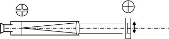
FIGURE 17.2 Alignment telescope with a reticle in the front focal plane, which allows the observation of the lateral deviation of a moving target from the reference line.
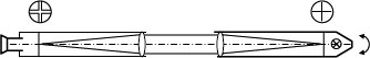
FIGURE 17.3 Alignment telescope with a reticle in the front focal plane, which allows the observation of the direction (tilt) of a collimator projecting the target to infinity.
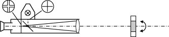
FIGURE 17.4 Autocollimator that allows the observation of the direction (tilt) of the mirror reflector.
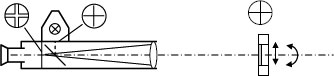
FIGURE 17.5 Alignment autocollimator as a combination of an alignment telescope and an autocollimator, which allows the observation of the lateral displacement and the direction of the moving target.
3. Autocollimator: In an autocollimator setup, the collimator is also used as the observation telescope. This is achieved by introducing a beam splitter close to the front focal plane of the collimator optics (Figure 17.4). In a photoelectric instrument where visual observation is superseded by an electronic readout, the illuminated reticle is replaced by a back-lighted slit or crossed slits for a two-axis instrument or an LED or laser diode. The setup from Figure 17.4 is, in fact, obtained by folding Figure 17.3 and replacing the collimator by a mirror. Consequently, the configuration serves in the alignment of the direction of the mirror mount with respect to an optical reference line.
4. Alignment autocollimator: Alignment autocollimators are a combination of the foregoing variants. They offer the possibility to measure both, the lateral displacement (straightness deviation) and the direction (tilting) of the target (Figure 17.5). The target is thus a combination of a mirror reflector and a reticle.
In modern alignment systems, the line of sight produced by an optical telescope is more and more replaced by a collimated laser beam (Figure 17.6). With the help of an electronic target (position-sensitive detector or four-quadrant detector), the deviation from the line of sight can be precisely measured and indicated on a display or recorded. This can be applied for straightness measurement of a moving carriage or for alignment of shafts or bores along a line of sight. The sensitivity of the target is dependent on its measurement range and the beam diameter and is typically in the order of 1–10 μm.
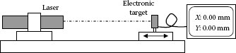
FIGURE 17.6 Straightness measurement or alignment using a collimated laser beam.
Attention has to be paid to the divergence of the laser beam due to diffraction. The diameter w(z) of a laser beam varies with the distance z by
where
w0 = w(0) is the beam diameter at its waist
λ is the optical wavelength
For example, a beam with a waist w0 = 1 mm will double its diameter after approximately 9 m, whereas a 2 mm waist will double after roughly 36 m.
17.3.3 STRAIGHTNESS INTERFEROMETER
Another method for straightness measurement based on an optical beam is the straightness interferometer (Figure 17.7). The polarizing interferometer consists of a birefringent prism (Wollaston prism), which splits the incoming beam into two bent beams of orthogonal polarization. A fixed angled mirror reflects the beams for recombination and interference in the prism. The interference signal is usually detected after a beam splitter within the housing of the laser head. A lateral displacement of the prism will change the optical path length between the two polarizations of the beam and induce a linear change in the interference phase. It is thus the prism that plays the role of the moving target.
Note that the straightness interferometer is only sensitive to one transversal direction. The measurement of the straightness deviation in the orthogonal direction necessitates the prism and the reflector to be rotated by 90°. The range of transversal displacement measurement is essentially limited by the size of the prism and is typically in the order of ±1 mm. The sensitivity is dependent on the angular separation of the beams. Given the practical limitations for the reflector size, a higher refracting prism and thus a larger beam angle may be used for shorter longitudinal measurement ranges. Sensitivities of 0.01 and 0.1 μm are typical for short and long range measurements, respectively.
The lateral displacement measurement of a straightness interferometer is intrinsically linear provided the polarizing prism is of sufficient optical quality. The straightness deviation along the longitudinal direction is not only given by the perfectly straight beam line, but also by flatness deviations of the angled reflector: depending on the distance of the interferometer from the reflector, the beam separation on the reflector will change accordingly and the beams will be reflected by another part of the mirrors. A flatness deviation of the mirrors will then be interpreted by the instrument as a straightness deviation. Attention must therefore be paid to the manufacturer’s specifications for distance-dependent accuracy.
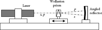
FIGURE 17.7 Straightness interferometer.
17.4 STRAIGHTNESS MEASUREMENT BASED ON A MECHANICAL DATUM
The straightness of an artifact can be measured by comparison to a mechanical datum, usually realized by a precision guide way with a low noise bearing such as a hydrostatic or an air bearing. The straightness difference of the artifact with respect to the datum is usually recorded by a mechanical displacement transducer such as an inductive probe (Figure 17.8a). The recorded profile P1(x) is then given by the difference of the straightness S(x) of the unknown artifact and the straightness SD(x) of the datum:
where R1(x) is a random noise term due to the non-repeatable behavior of the bearing and the electronic noise of the transducer. The straightness S(x) of the straight edge under test is then given by
The straightness deviation SD(x) of the datum is ideally sufficiently small or corrected by error mapping, eventually known from another source. The uncertainty u(S) is given by
where σ2 is the variance of the noise term (or σ the root mean square, rms).
17.4.1 ERROR SEPARATION BY REVERSAL
An additional reversal measurement allows to determine the straightness error of the artifact independent of the straightness error of the reference datum. For this, the straight edge under test is reversed in its position such that the measurement surface is oriented toward the opposite direction and has to be probed from the other side (Figure 17.8b). The measured profile is then given by
With this, the straightness error of both, the artifact and the datum, can be determined independently:
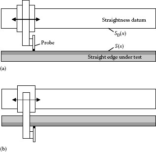
FIGURE 17.8 (a) Straightness measurement using a linear guide way as mechanical datum and (b) reversal measurement for error separation.
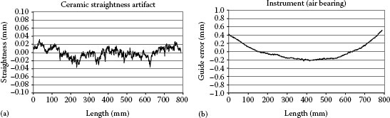
FIGURE 17.9 (a) Measured straightness deviation on a ceramic artifact and (b) guide error of the instrument used, resulting from error separation by reversal.
where is the combined noise term assuming the noise to be uncorrelated.
The uncertainty of the measured straightness profile is now only limited by the repeatability and noise R(x) of the bearing and the transducer, described by its rms value, and the stability of the straight edge due to mechanical constraints and thermal gradients, which are both difficult to estimate other than from experimental data.
Reversal straightness measurements were made using a 1000 mm granite beam with a vacuum-preloaded air-bearing slide of 800 mm travel. The carriage is moved by a low noise DC motor by means of a steel chord. The position of the carriage is measured by an incremental scale. The straightness deviation is measured in horizontal direction by an inductive probe. The measured artifact is a ceramic straight edge of 54 mm × 93 mm × 1016 mm.
The local reproducibility of independent straightness measurements turned out to be in the order of 3 nm standard deviation, whereas the length-dependent reproducibility was smaller than 5 × 10⁻⁸·L, with L being the length of the straightness profile. This latter term is mainly due to the mechanical stability of the straight edge under test during the measurement process and thermal gradients inducing an irreproducible bending.
Figure 17.9a and b shows the resulting straightness profiles S(x) and SD(x) of the straightness artifact and the instruments, guide error, respectively. The straightness deviation of the ceramic straight edge was measured to be STRt = 0.07 µm over a length of 800 mm. The short wavelength structure as shown in Figure 17.9 for the ceramic artifact was perfectly reproducible and therefore not caused by noise but due to the surface structure.
17.5 STRAIGHTNESS MEASUREMENT USING ANGLE INSTRUMENTS
The straightness of artifacts may also be determined by integration of local slopes on discrete intervals. These slopes are measured with the help of angle instruments, either as inclinations with respect to the horizontal direction given by the gravitational field or as angles of a target with respect to an optical beam. The heights hi in the discrete points along the measured profile (Figure 17.10) are given by a recursive formula:
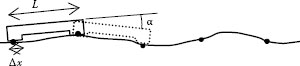
FIGURE 17.10 Straightness deviation represented by a height profile measured from local slopes on discrete intervals.
where L is the length of the base.
For the optimum choice of the base length L, there is a trade-off between the resolution (density of the measurement points) and the accuracy: a short base length L means that only small slope changes are observed. When these small values become comparable with random errors, the integration of these when applying the recursive formula for calculating the heights leads to an undue accumulation of uncertainty. Furthermore, a large number of measurement points increase the measurement time and thus potential drift.
The length Δx of the contact surfaces is usually chosen to be much smaller than the base length but sufficiently large to achieve some averaging over the microstructure of the surface and also to have reduced requirements for the positioning accuracy of the base at the intended positions.
Electronic levels are devices that measure the inclination from horizontal direction. The sensor is based commonly on a friction-free pendulum, whose amplitude is measured by a linear differential inductive or capacitive transducer. Electronic levels are available with resolutions down to 0.1”, corresponding to a height difference of 0.05 μm/100 mm base length. Figure 17.11 shows the application of electronic levels for the measurement of straightness along a given direction on a surface plate. The use of a differential mode with two instruments, one of them in a fixed position, removes the influence of a rigid body motion of the whole plate during the measurements. The limiting factors for such measurements are vibrations and thermal drift of the levels during the measurement time due to the continuous handling of the instruments.
Autocollimators as described in Section 17.3.1 measure the tilt angle of the reflector mirror and thus the inclination of the base plate supporting the mirror. Their application for straightness measurement is straight forward as shown in Figure 17.12. The angle resolution of autocollimators is potentially much smaller than that for most of the other angle instruments and are in the order of 0.01”–0.1” for standard commercial instruments. In metrological high-end applications using highly precise instruments and a fully automatic positioning of the reflector unit, straightness measurement uncertainties in the nanometer region were reported. The quality of the collimator optics (apparent angle deviation with increasing distance) and air turbulence are setting the ultimate limitations for straightness measurement uncertainty.
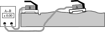
FIGURE 17.11 Straightness measurement of a surface plate using electronic levels in the differential mode.
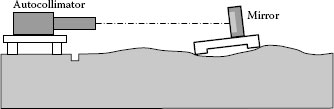
FIGURE 17.12 Straightness measurement of a surface plate using an autocollimator.
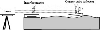
FIGURE 17.13 Straightness measurement of a surface plate using an angle interferometer.
An angle interferometer is an interferometer where the optical path is folded in such a way that the measurement beams and the reference beams are parallel side by side (Figure 17.13). By its sensitivity to the optical path length difference , where φ is the measured interference phase, the tilt angle α of the reflector is obtained by
where S is the distance between the two corner cube reflectors.
The resolution of commercial angle interferometers is typically in the order of 0.1”. When taking into account the arcsin correction, angle interferometers are perfectly linear within a large range up to about ±10°.
The application of angle interferometers to the measurement of artifact straightness is analogous to the use of autocollimators. It has to be noted that the interferometer optics serves for the reference and must be situated on the same surface plate in order to avoid any influence of a rigid body motion of the plate, whereas the position of the laser is not critical and may be on a tripod beside the plate.
The carriage of a linear machine axis is ideally described by a rectilinear, perfectly straight movement. Modeling the real geometry of a machine axis implies all 6 degrees of freedom (DOF) of a rigid body in space, that is, three translational and three rotational movements. The longitudinal DOF describes the principal movement of the carriage, whereas the remaining two transversal DOFs and the three rotational DOFs are fixed by the guide way. Their deviation functions describe the guide errors.
Figure 17.14 shows the model of a linear x-axis. The deviation function Txy(x) denotes the transversal deviation of the x-axis in y-direction, that is, the horizontal straightness, and the function Txz(x) consequently denotes the transversal deviation of the x-axis in z-direction, that is, the vertical straightness. The deviation function Rxy(x) is the rotational movement of the x-axis around the y-axis, denoted as pitch error. The rotational movements Rxz(x) and Rxx(x) around the z-axis and the x-axis are called yaw and roll errors, respectively.
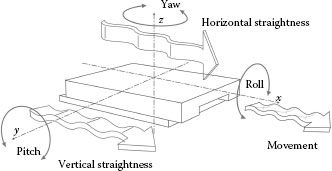
FIGURE 17.14 Representation of a carriage on a linear x-axis showing the geometrical errors of a guide way.
Obviously, there is some dependence between rotational guide errors and straightness deviation, but it is by far not trivial and often impossible to predict or model this. For example, a horizontal straightness error Txy may be caused by a yaw error Rxz, but dependent on the offset and its direction of the measurement axis from the center or origin of the axis, the other rotational errors Rxy and Rxx may contribute as well. In modern machine tools or measuring machines, the relevant guide errors are measured and subsequently mapped for correction.
17.6.1 STRAIGHTNESS MEASUREMENT OF A MACHINE AXIS
The straightness of a machine axis may be measured with any of the following instruments that were described above: alignment telescope (Section 17.3.1), laser beam alignment (Section 17.3.2), straightness interferometer (Section 17.3.3), or in comparison with a known straightness artifact. Care has to be taken when comparing any of the optical straightness measurement methods, where the straightness of a moving point in space is measured with a mechanical measurement using an artifact where in some configurations the mechanical probe may be fixed in space (typically in the tool holder of a machine tool), and the straight edge is moving with the carriage. In the latter case, the measurand is not the straightness of the moving axis, however, it is the function used for error mapping of the axis.
17.6.2 ROTATIONAL ERROR MEASUREMENT OF A MACHINE AXIS
• Pitch and yaw of a horizontal axis can be measured with the help of an autocollimator or an angle interferometer; yaw also with an electronic level. A dual axis autocollimator has the advantage that both rotational errors may be measured at the same time.
• Pitch and yaw of a vertical axis can be measured with electronic levels or with the help of an autocollimator or an angle interferometer if the optical beam is bent into vertical direction.
• Roll of a horizontal axis can be measured with the help of electronic levels.
• Roll of a vertical axis cannot be measured by either of the above mentioned means. Usually, these measurements are carried out using a vertical straightness standard (straight edge or cylinder) and an off-axis probe.
1. ISO/TS 12780-1, 2003, Geometrical product specifications (GPS)—Straightness. Part 1: Terms, definitions and parameters of straightness.