Day 31. Enterprise Network Architecture
ENCOR 350-401 Exam Topics
• Explain the different design principles used in an enterprise network
• Enterprise network design such as Tier 2, Tier 3, and Fabric Capacity planning
Key Topics
Today we review the hierarchical LAN design model, as well as the options available for different campus network deployments. This high-level overview of the enterprise campus architectures can be used to scale from a small corporate network environment to a large campus-sized network. We will look at design options such as:
• Two-tier design (collapsed core)
• Three-tier design
• The Layer 2 access layer (STP based)—both loop-free and looped
• The Layer 3 access layer (routed based)
• Simplified campus design using VSS and StackWise
• Software-Defined Access (SD-Access) design
• Spine-and-leaf architecture
Hierarchical LAN Design Model
The campus LAN uses a hierarchical design model to break up the design into modular groups or layers. Breaking up the design into layers allows each layer to implement specific functions, which simplifies the network design and therefore the deployment and management of the network.
In flat or meshed network architectures, even small configuration changes tend to affect many systems. Hierarchical design helps constrain operational changes to a subset of the network, which makes the network easy to manage and improves resiliency. Modular structuring of the network into small, easy-to-understand elements also facilitates resiliency via improved fault isolation.
A hierarchical LAN design includes three layers:
• Access layer: Provides endpoints and users direct access to the network.
• Distribution layer: Aggregates access layers and provides connectivity to services.
• Core layer: Provides backbone connectivity between distribution layers for large LAN environments, as well as connectivity to other networks within or outside the organization.
Figure 31-1 illustrates a hierarchical LAN design using three layers.

Figure 31-1 Hierarchical LAN Design
Access Layer
The access layer is where user-controlled devices, user-accessible devices, and other endpoint devices are connected to the network. The access layer provides both wired and wireless connectivity and contains features and services that ensure security and resiliency for the entire network. The access layer provides high-bandwidth device connectivity, as well as a set of network services that support advanced technologies, such as voice and video. The access layer—which provides a security, QoS, and policy trust boundary—is one of the most feature-rich parts of the campus network. It offers support for technologies like Power over Ethernet (PoE) and Cisco Discovery Protocol (CDP) for deployment of wireless access points (APs) and IP phones. Figure 31-2 illustrates connectivity at the access layer.

Figure 31-2 Access Layer Connectivity
Distribution Layer
In a network where connectivity needs to traverse the LAN end-to-end, whether between different access layer devices or from an access layer device to the WAN, the distribution layer facilitates this connectivity. The distribution layer provides scalability and resilience as it is used to logically aggregate the uplinks of access switches to one or more distribution switches. Scalability is accomplished via the aggregation of those access switches, and resilience is accomplished through the logical separation with multiple distribution switches. The distribution layer is the place where routing and packet manipulation are performed, and this layer can be a routing boundary between the access and core layers, where QoS and load balancing are implemented.
Figure 31-3 illustrates connectivity at the distribution layer.

Figure 31-3 Distribution Layer Connectivity
Core Layer
The core layer is the high-speed backbone for campus connectivity, and it is the aggregation point for the other layers and modules in the hierarchical network architecture. It is designed to switch packets with minimal processing as fast as possible 24x7x365. The core must provide a high level of stability, redundancy, and scalability. In environments where the campus is contained within a single building—or multiple adjacent buildings with the appropriate amount of fiber—it is possible to collapse the core into distribution switches. Without a core layer, the distribution layer switches need to be fully meshed. Such a design is difficult to scale and increases the cabling requirements because each new building distribution switch needs full-mesh connectivity to all the distribution switches. The routing complexity of a full-mesh design increases as you add new neighbors.
Figure 31-4 illustrates networks with and without a core layer. The core layer reduces the network complexity, from N * (N – 1) to N links for N distributions if using link aggregation to the core, as shown in Figure 31-4; it would be N * 2 if using individual links to a redundant core.
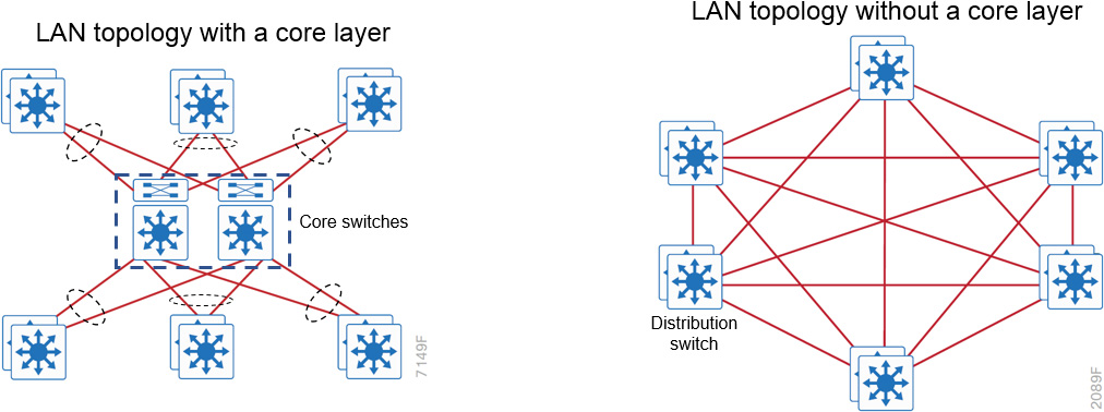
Figure 31-4 LAN Topology With and Without a Core Layer
Enterprise Network Architecture Options
There are multiple enterprise network architecture design options available for deploying a campus network, depending on the size of the campus as well as the reliability, resiliency, availability, performance, security, and scalability required for it. Each possible option should be evaluated against business requirements. Since campus networks are modular, an enterprise network could have a mixture of these options.
Two-Tier Design (Collapsed Core)
The distribution layer provides connectivity to network-based services, to the data center/server room, to the WAN, and to the Internet edge. Network-based services can include but are not limited to Cisco Identity Services Engine (ISE) and wireless LAN controllers (WLCs). Depending on the size of the LAN, these services and the interconnection to the WAN and Internet edge may reside on a distribution layer switch that also aggregates the LAN access layer connectivity. This is also referred to as a collapsed core design because the distribution serves as the Layer 3 aggregation layer for all devices.
It is important to consider that in any campus design—even designs that can be physically built with a collapsed core—the primary purpose of the core is to provide fault isolation and backbone connectivity. Isolating the distribution and core into two separate modules creates a clean delineation for change control between activities that affect end stations (laptops, phones, and printers) and activities that affect the data center, WAN, or other parts of the network. A core layer also provides for flexibility in adapting the campus design to meet physical cabling and geographic challenges.
Figure 31-5 illustrates a collapsed LAN core.
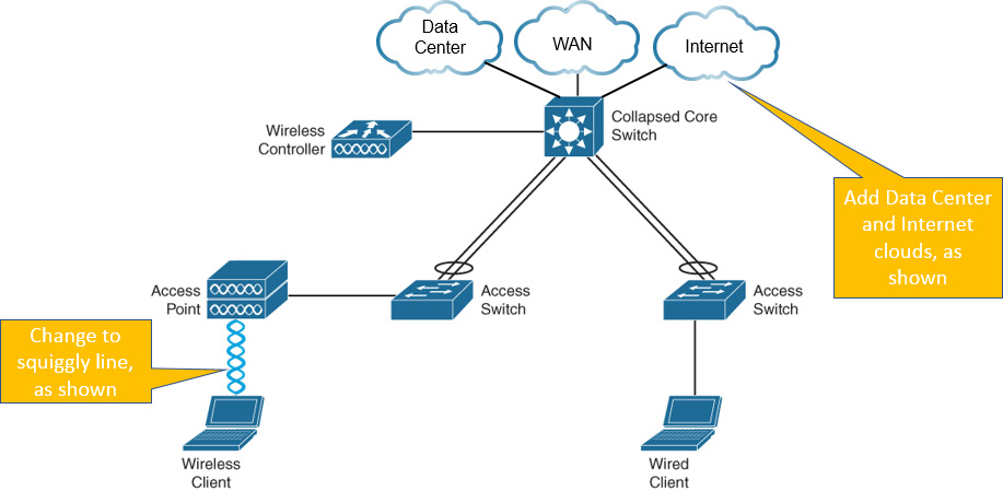
Figure 31-5 Two-Tier Design: Distribution Layer Functioning as a Collapsed Core
Three-Tier Design
In a large LAN, it would be difficult to share connectivity with access layer devices; therefore, a large LAN design may require a dedicated distribution layer for network-based services. As the density of WAN routers, Internet edge devices, and WLAN controllers grows, connections to individual distribution layer switches become hard to manage. When connecting at least three distribution layers together, using a core layer for distribution layer connectivity should be a consideration.
The three-tier campus network design is mostly deployed in environments where multiple offices and buildings are located closely together, allowing for high-speed fiber connections to the headquarters owned by the enterprise. Examples include the campus network at a university, a hospital with multiple buildings, and a large enterprise with multiple buildings on a privately owned campus. Figure 31-6 illustrates a typical three-tier campus network design.
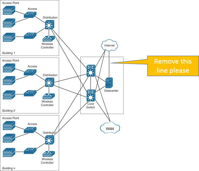
Figure 31-6 Three-Tier Design for a Large Campus Network
Layer 2 Access Layer (STP Based): Loop-Free and Looped
In the traditional hierarchical campus design, distribution blocks use a combination of Layer 2, Layer 3, and Layer 4 protocols and services to provide for optimal convergence, scalability, security, and manageability. In the most common distribution block configurations, the access switch is configured as a Layer 2 switch that forwards traffic on high-speed trunk ports to the distribution switches. Distribution switches are configured to support both Layer 2 switching on their downstream access switch trunks and Layer 3 switching on their upstream ports toward the core of the network.
With traditional Layer 2 access layer design, there is no true load balancing because STP blocks redundant links. Load balancing can be achieved through manipulation of STP and FHRP (HSRP, VRRP) settings and having traffic from different VLANs on different links. However, manual STP and FHRP manipulation is not true load balancing. Another way to achieve good load balancing is by limiting VLANs on a single switch and employing GLBP, but such a design could get complex. Convergence can also be an issue. Networks using RSTP have convergence times just below a second, but subsecond convergence is possible only with good hierarchical routing design and tuned FHRP settings and timers.
Figure 31-7 illustrates two Layer 2 access layer topologies: loop-free and looped. In a loop-free topology, a VLAN is constrained to a single switch, and a Layer 3 link is used between distribution layer switches to break the STP loop, ensuring that there are no blocked ports from the access layer to the distribution layer. In a looped topology, a VLAN spans multiple access switches. In this case, a Layer 2 trunk link is used between distribution layer switches. This design causes STP to block links, which reduces the bandwidth from the rest of the network and can cause slower network convergence.
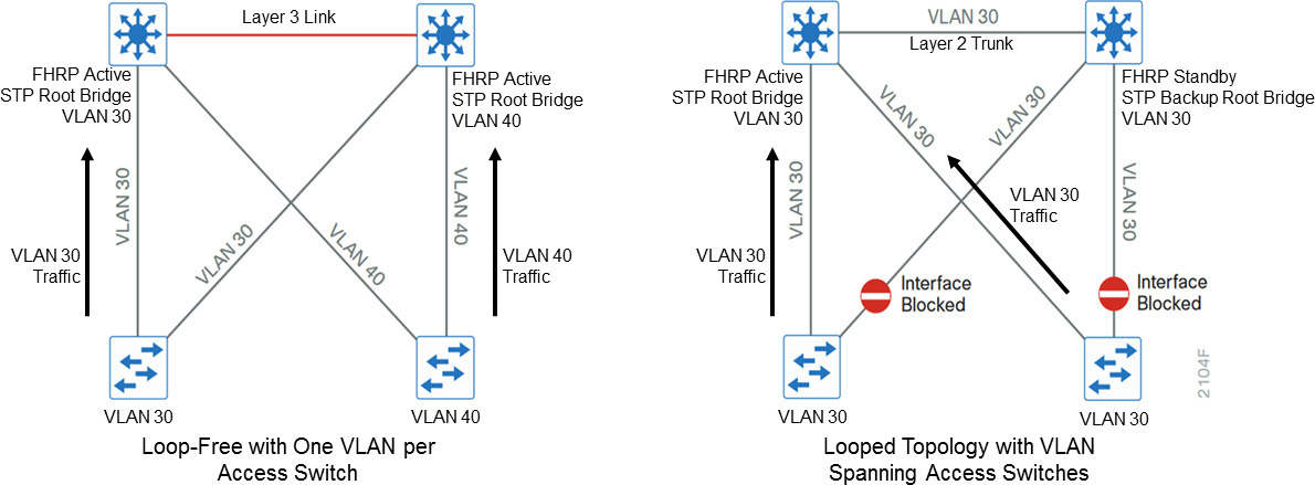
Figure 31-7 Layer 2 Loop-Free and Looped Topologies
Layer 3 Access Layer (Routed Based)
An alternative configuration to the traditional distribution block model is one in which the access switch acts as a full Layer 3 routing node. The access-to-distribution Layer 2 uplink trunks are replaced with Layer 3 point-to-point routed links. This means the Layer 2/3 demarcation is moved from the distribution switch to the access switch. There is no need for FHRP, and every switch in the network participates in routing.
In both the traditional Layer 2 access layer and the Layer 3 routed access layer designs, each access switch is configured with unique voice and data VLANs. In the Layer 3 design, the default gateway and root bridge for these VLANs is simply moved from the distribution switch to the access switch. Addressing for all end stations and for the default gateway remain the same. VLAN and specific port configuration remains unchanged on the access switch. Router interface configuration, access lists, DHCP Helper, and other configurations for each VLAN remain identical. However, they are now configured on the VLAN SVI defined on the access switch instead of on the distribution switches. There are several notable configuration changes associated with the move of the Layer 3 interface down to the access switch. It is no longer necessary to configure an FHRP virtual gateway address as the “router” interfaces because all the VLANs are now local.
Figure 31-8 illustrates the difference between the traditional Layer 2 access layer design and the Layer 3 routed access layer design.

Figure 31-8 Layer 2 Access Layer and Layer 3 Access Layer Designs
Simplified Campus Design Using VSS and StackWise
An alternative that can handle Layer 2 access layer requirements and avoid the complexity of the traditional multilayer campus is called a simplified campus design. This design uses multiple physical switches that act as a single logical switch, using either Virtual Switching System (VSS) or StackWise. One advantage of this design is that STP dependence is minimized, and all uplinks from the access layer to the distribution layer are active and forwarding traffic. Even the distributed VLAN design eliminates spanning tree blocked links caused by looped topologies. It is also possible to reduce dependence on spanning tree by using Multichassis EtherChannel (MEC) from the access layer with dual-homed uplinks. This is a key characteristic of this design, and load balancing between the physical distribution switches is possible because the access layer sees VSS as a single switch.
There are several other advantages to the simplified distribution layer design. Such a design does not need IP gateway redundancy protocols such as HSRP, VRRP, and GLBP because the default IP gateway is on a single logical interface, and resiliency is provided by the distribution layer VSS switch. Also, the network converges faster because it does not depend on spanning tree to unblock links when a failure occurs, thanks to MEC’s fast subsecond failover between links in an uplink bundle.
Figure 31-9 illustrates the deployment of both StackWise and VSS technologies. In the top diagram, two access layer switches have been united into a single logical unit by using special stack interconnect cables that create a bidirectional closed-loop path. This bidirectional path acts as a switch fabric for all the connected switches. When a break is detected in a cable, the traffic is immediately wrapped back across the remaining path to continue forwarding. Also, in this scenario, the distribution layer switches are each configured with an EtherChannel link to the stacked access layer switches. This is possible because the two access layer switches are viewed as one logical switch from the perspective of the distribution layer.
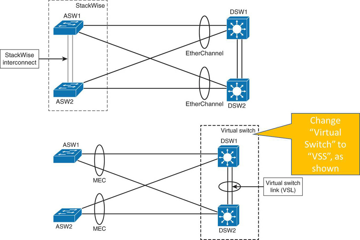
Figure 31-9 Simplified Campus Design with VSS and StackWise
In the bottom diagram, the two distribution layer switches have been configured as a VSS pair using a virtual switch link (VSL). The VSL is composed of up to eight 10 Gigabit Ethernet connections that are bundled into an EtherChannel. The VSL carries the control plane communication between the two VSS members, as well as regular user data traffic. Notice the use of MEC at the access layer. This allows the access layer switch to establish an EtherChannel to the two different physical chassis of the VSS pair. These links can be either Layer 2 trunks or Layer 3 routed connections.
Keep in mind that it is possible to combine StackWise and VSS in a campus network. They are not mutually exclusive. StackWise is typically found at the access layer, whereas VSS is found at the distribution and core layers.
Common Access–Distribution Interconnection Designs
To summarize, there are four common access-–distribution interconnection design options:
• Layer 2 looped design: Uses Layer 2 switching at the access layer and on the distribution switch interconnect. This introduces a Layer 2 loop between distribution switches and access switches. STP blocks one of the uplinks from the access switch to the distribution switches. The reconvergence time in the event of uplink failure depends on STP and FHRP convergence times.
• Layer 2 loop-free design: Uses Layer 2 switching at the access layer and Layer 3 routing on the distribution switch interconnect. There are no Layer 2 loops between the access switch and the distribution switches. Both uplinks from the access layer switch are forwarding. Reconvergence time in the event of an uplink failure depends on the FHRP convergence time.
• VSS design: Results in STP recognizing an EtherChannel link as a single logical link. STP is thus effectively removed from the access–distribution block. STP is needed only on access switch ports that connect to end devices to protect against end-user-created loops. If one of the links between access and distribution switches fails, forwarding of traffic continues without the need for reconvergence.
• Layer 3 routed design: Uses Layer 3 routing on the access switches and the distribution switch interconnect. There are no Layer 2 loops between the access layer switch and distribution layer switches. The need for STP is eliminated, except on connections from the access layer switch to end devices to protect against end-user wiring errors. Reconvergence time in the event of uplink failure depends solely on the routing protocol convergence times.
Figure 31-10 illustrates the four access–distribution interconnection design options.
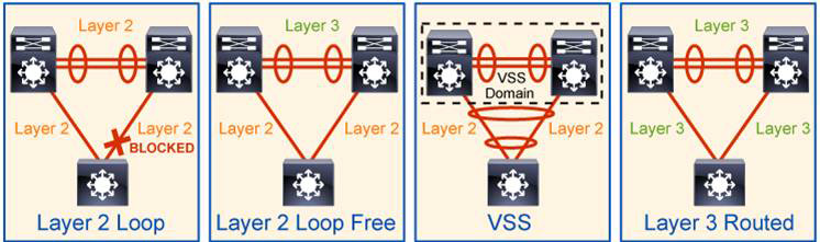
Figure 31-10 Access–Distribution Interconnection Design Options
Software-Defined Access (SD-Access) Design
You can overcome the Layer 2 limitations of the routed access layer design by adding fabric capability to a campus network that is already using a Layer 3 access network; the addition of the fabric is automated using SD-Access technology. The SD-Access design enables the use of virtual networks (called overlay networks) running on a physical network (called the underlay network) in order to create alternative topologies to connect devices. In addition to network virtualization, SD-Access allows for software-defined segmentation and policy enforcement based on user identity and group membership, integrated with Cisco TrustSec technology. Figure 31-11 illustrates the relationship between the physical underlay network and the Layer 2 virtual overlay network used in SD-Access environments. SD-Access is covered in more detail on Day 17.
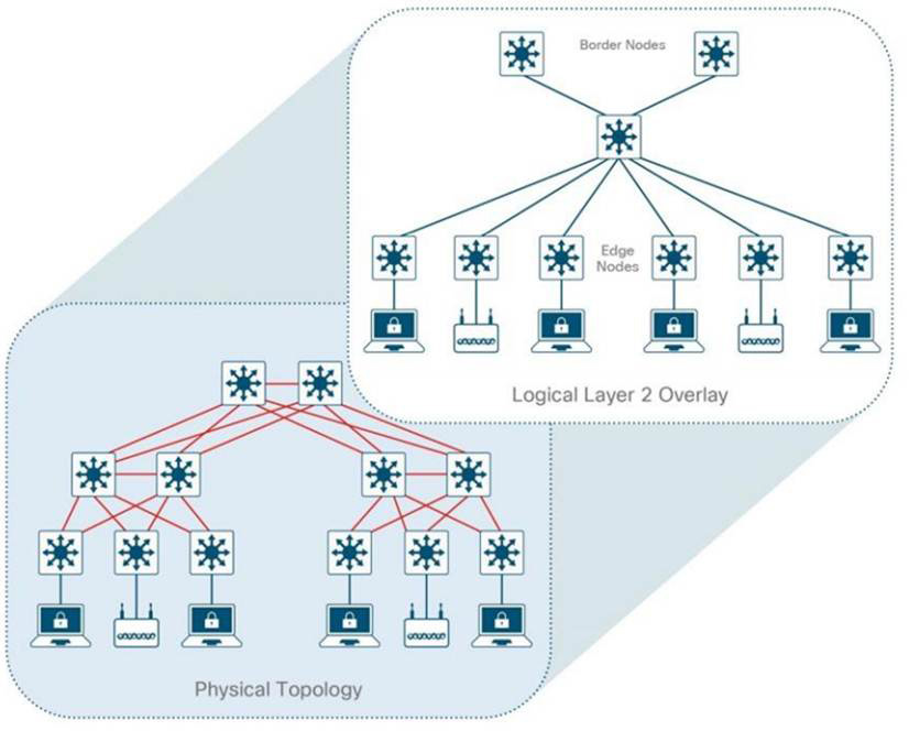
Figure 31-11 Layer 2 SD-Access Overlay
Spine-and-Leaf Architecture
A new data center design called the Clos network–based spine-and-leaf architecture was developed to overcome limitations such as server-to-server latency and bandwidth bottlenecks typically found in three-tier data center architectures. This new architecture has been proven to deliver the high-bandwidth, low-latency, nonblocking server-to-server connectivity needed to support high-speed workloads and shift the focus from earlier 1 Gbps or 10 Gbps uplinks to the modern 100 Gbps uplinks necessary in today’s data centers. Figure 31-12 illustrates a typical two-tiered spine-and-leaf topology.

Figure 31-12 Typical Spine-and-Leaf Topology
In this two-tier Clos architecture, every lower-tier switch (leaf layer) is connected to each of the top-tier switches (spine layer) in a full-mesh topology. The leaf layer consists of access switches that connect to devices such as servers. The spine layer, which is the backbone of the network, is responsible for interconnecting all leaf switches. Every leaf switch connects to every spine switch in the fabric. A path through the network is randomly chosen so that the traffic load is evenly distributed among the top-tier switches. If one of the top-tier switches were to fail, performance throughout the data center would degrade only slightly.
If oversubscription of a link occurs (that is, if more traffic is generated than can be aggregated on the active link at one time), the process for expanding capacity is straightforward: An additional spine switch can be added, and uplinks can be extended to every leaf switch, resulting in the addition of interlayer bandwidth and reduction of the oversubscription. If device port capacity becomes a concern, it is possible to add a new leaf switch by connecting it to every spine switch and adding the network configuration to the switch. The ease of expansion optimizes the IT department’s process of scaling the network. If no oversubscription occurs between the lower-tier switches and their uplinks, a nonblocking architecture can be achieved.
With a spine-and-leaf architecture, no matter which leaf switches are connected to servers, the traffic always has to cross the same number of devices to get to another server (unless the other server is located on the same leaf). This approach keeps latency at a predictable level because a payload only has to hop to a spine switch and another leaf switch to reach its destination.
Study Resources
For today’s exam topics, refer to the following resources for more study.