Day 9. Secure Network Access
ENCOR 350-401 Exam Topics
• Security
• Describe the components of network security design
• Threat defense
• Endpoint security
• Next-generation firewall
• TrustSec, MACsec
• Network access control with 802.1X, MAB, and WebAuth
Key Topics
Today we start our review of network security concepts by focusing on the enterprise network security architecture. Today’s enterprise networks carry sensitive data belonging to both the enterprise and its customers. Understanding threats that face networks and ways to address these threats is an important part of operations in today’s enterprise networks. Today we also look at how we can apply a layered approach to defending the network by using different security tools and services.
Network Security Threatscape
Threats to the enterprise network can come in many forms and from many sources, both external and internal. This multitude of threats and sources is referred to as the threatscape.
It is easy to recognize the need for improved network security just by monitoring the news. Every few months, there is a new story about large companies falling victim to attacks, and thereby losing huge amounts of private data and intellectual property. No industry is exempt. Companies in the financial, retail, entertainment, energy, and technology industries have all been compromised.
Attackers are not limited to individuals or small teams of hackers. Organized crime and even national governments (state-sponsored cyberattacks) are often implicated in attacks. Today's attackers are exceedingly clever and devious and have vast supporting funding and resources.
As a defender, you must not be restricted by preconceptions of how things are designed to work or strict classification of known network threats. Attackers don’t restrict themselves. Attackers are creative thinkers. Attackers combine old and new techniques to produce unique new threats. As a defender, you too must be prepared to think outside the box and evolve to respond to the ever-changing threatscape.
Here is some terminology that will help you as you learn about today's threatscape:
• Vulnerability: A weakness that compromises either the security or the functionality of a system. Weak or easily guessed passwords are considered vulnerabilities.
• Exploit: The mechanism that is used to leverage a vulnerability to compromise the security or functionality of a system. An example of an exploit is an exploit tool. When a vulnerability is disclosed to the public, attackers often create a tool that implements an exploit for that specific vulnerability. If they release the tool to the Internet, other attackers with very little skill can effectively exploit the vulnerability.
• Threat: Any circumstance or event that has the potential to cause harm to an asset in the form of destruction, disclosure, adverse modification of data, or DoS. An example of a threat is malicious software that targets workstations.
• Risk: The likelihood that a particular threat using a specific attack will exploit a particular vulnerability of an asset and result in an undesirable consequence.
The threatscape is a very large concept that is constantly growing. Many threat vectors can impact the enterprise network, from many different types of attackers. To help understand the rage of threats, here is a summary of some of the major types of attacks and threats:
• DoS and DDoS: Denial-of-service (DoS) and distributed denial-of-service (DDoS) attacks attempt to consume all of a critical computer or network resource to make it unavailable for valid use. A DoS attack is initiated by a single source, whereas a DDoS attack comes from a multitude of sources.
• Spoofing: An attack can be considered a spoofing attack any time an attacker injects traffic that appears to be sourced from a trusted system other than the attacker's system itself. Spoofing is not specifically an attack, but spoofing can be incorporated into various types of attacks.
• Reflection: A reflection attack is a type of DoS attack in which the attacker sends a flood of protocol request packets to various IP hosts. The attacker spoofs the source IP address of the packets such that each packet has as its source address the IP address of the intended target rather than the IP address of the attacker. The IP hosts that receive these packets become "reflectors." The reflectors respond by sending response packets to the spoofed address (the target), thus flooding the unsuspecting target.
• Social engineering: Social engineering involves manipulating people and capitalizing on expected behaviors. Social engineering often involves utilizing social skills, relationships, or understanding of cultural norms to manipulate people inside a network to provide the information that is needed to access the network.
• Phishing: Phishing is a common social engineering technique. Typically, a phishing email pretends to be from a large, legitimate organization. The large organization is legitimate, and the target may have a real account with the organization. The malicious website generally resembles that of the real organization. The goal is to get the victim to enter personal information such as account numbers, Social Security numbers, usernames, or passwords. Phishing can also be conducted using telephone system to achieve the same kind of social engineering. In that case, it is called vishing.
• Password attacks: Password attacks have been a problem since network security came into being, and they continue to be a dominant problem in current network security. An attacker tries to access protected resources by obtaining a user’s password. Methods for retrieving the user’s password include guessing, brute-force, and dictionary attacks. Many authentication systems require a certain degree of password complexity. Specifying a minimum length for a password and forcing an enlarged character set (uppercase, lowercase, numeric, and special characters) can have an enormous influence on the feasibility of brute-force attacks.
• Reconnaissance attacks: A reconnaissance attack is an attempt to learn more about the intended victim before mounting a more intrusive attack. Attackers can use standard networking tools such as the command-line tools dig, nslookup, and whois to gather public information about a target network from DNS registries. The nslookup and whois tools are available on Windows, UNIX, and Linux platforms, and dig is available on UNIX and Linux systems.
• Buffer overflow attacks: Attackers can analyze network server applications for flaws. A buffer overflow vulnerability is one type of flaw. If a service accepts input and expects the input to be within a certain size but does not verify the size of input upon reception, it may be vulnerable to a buffer overflow attack. This means that an attacker can provide input that is larger than expected, and the service will accept the input and write it to memory, filling up the associated buffer and overwriting adjacent memory. This overwrite may corrupt the system and cause it to crash, resulting in DoS. In the worst cases, the attacker can inject malicious code in the buffer overflow, which may lead to a system compromise.
• Man-in-the-middle attacks: Generally, in a man-in-the-middle attack, a system that has the ability to view the communication between two systems imposes itself in the communication path between those other systems. Man-in-the-middle attacks are complex and require successful attacks against protocols such as Address Resolution Protocol (ARP), Domain Name System (DNS), or Dynamic Host Configuration Protocol (DHCP), resulting in the misdirection of traffic.
• Malware: Malware is malicious software that comes in several forms, including viruses, worms, and Trojan horses. The common thread of these attacks is that the attacker tries to install software on the victim’s system. Once the software is installed on the victim’s system, the attacker can take control of that system, encrypt and lock the victim’s data, or escalate privileges to other parts of the victim’s network as part of an advanced persistent threat (APT).
• Vectors of data loss and exfiltration: The expression vector of data loss and exfiltration refers to the means by which data leaves an organization without authorization. While not a direct attack itself, it is a major security concern in the enterprise network. Many of the tools that make our jobs easier today also make it possible for confidential data to be obtained by unauthorized persons. Some common data loss vectors include email attachments, unencrypted devices, cloud storage services, removable storage devices, and improper access controls.
• Hacking tools: The distinction between a security tool and an attack tool is in the intent of the user. A penetration tester legitimately uses tools to attempt to penetrate an organization’s security defenses, and the organization uses the results of the penetration test to improve its security defenses. However, an attacker can also use the same tools that the penetration tester uses. Hacking tools include sectools.org, Kali Linux, and Metasploit.
For more information about threats facing today’s enterprise network, visit Cisco Talos, at www.talosintelligence.com.
Network Security Components
This section describes different threat defense solutions and components that can be deployed within a network to protect it against the attacks listed earlier.
Intrusion Prevention Systems
An intrusion prevention systems (IPS) is a system that performs deep analysis of network traffic, searching for signs of suspicious or malicious behavior. If it detects such behavior, the IPS can take protective action. Because it can perform deep packet analysis, an IPS can complement a firewall by blocking attacks that would normally pass through a traditional firewall device. For example, an IPS can detect and block a wide range of malicious files and behavior, including botnet attacks, malware, and application abuse.
Figure 9-1 shows a firewall and an IPS working in conjunction to defend a network. This is an example of network-based IPS, in which IPS devices are deployed at designated network points to address network attacks, regardless of the location of the attack target. Network-based IPS technology is deployed in a sensor, which can be a dedicated appliance or a module that is installed in another network device. There are also host-based IPSs that only detect attacks that occur on the hosts on which they are installed.

Figure 9-1 Intrusion Prevention System
IPSs use several methods of traffic inspection:
• Signature-based inspection: A signature-based IPS examines the packet headers or data payloads in network traffic and compares the data against a database of known attack signatures. The database must be continually updated to remain effective. A signature might be a sequence or a string of bytes in a certain context. Signature-based inspection is sometimes referred to as rule-based or pattern-matching inspection.
• Anomaly-based inspection: Anomaly-based network IPS devices observe network traffic and act if a network event outside normal network behavior is detected.
There are three types of anomaly-based network inspection:
• Statistical anomaly detection (network behavior analysis): This type of inspection involves observing network traffic over time and building a statistical profile of normal traffic behavior, based on communication patterns, traffic rate, mixture of protocols, and traffic volume. After a normal profile has been established, statistical anomaly detection systems detect or prevent activity that violates the normal profile.
• Protocol verification: This type of inspection involves observing network traffic and comparing network, transport, and application layer protocols that are used inside network traffic to protocol standards. If a deviation from standards-based protocol behavior (such as a malformed IP packet) is detected, the system can take appropriate action.
• Policy-based inspection: A policy-based IPS analyzes network traffic and takes action if it detects a network event outside configured traffic policy.
Modern IPSs, which are often called next-generation IPSs (NGIPSs), combine the benefits of these inspection methods. They utilize technology such as traffic normalization and protocol decoding to counter evasive attacker techniques and to improve efficacy. They also utilize newer and more sophisticated technologies, such as reputation, context awareness, event correlation, and cloud-based services, to provide more robust and flexible protection. IPS services are often combined with firewall appliances or services, as is the case with next-generation firewalls (NGFW).
Virtual Private Networks
As discussed on Day 20, “GRE and IPsec,” a virtual private network (VPN) is a technology that secures communication across an untrusted network. As defined in RFC 2828 and RFC 4949, a VPN is “a restricted-use, logical (i.e., artificial or simulated) computer network that is constructed from the system resources of a relatively public, physical (i.e., real) network (such as the Internet), often by using encryption (located at hosts or gateways), and often by tunneling links of the virtual network across the real network.”
A VPN carries private traffic over a public or shared infrastructure (such as the Internet). The most common and effective VPN technology is applied at the network layer of the OSI model to encrypt traffic flow among specific users, applications, or IP subnet pairs. A VPN at the network layer is transparent to the applications at higher OSI layers and is also independent of network topology.
VPNs are classified according to the following criteria:
• Deployment mode: A VPN may be deployed as a site-to-site VPN or as a remote-access VPN. A site-to-site VPN provides an Internet-based WAN infrastructure for connecting branch offices, home offices, or the sites of business partners to all or portions of a network. A remote-access VPN provides secure communications for remote access to networks and applications. Hosts can establish remote-access VPNs either by using VPN client software or by using an SSL-enabled web browser.
• Underlying technology: VPNs can be classified according to the technology they use, including IPsec VPN, SSL VPN, Multiprotocol Label Switching (MPLS) VPN, other Layer 2 technologies such as Frame Relay or Asynchronous Transfer Mode (ATM), and hybrid VPNs combining multiple technologies.
Content Security
Content security systems provide fine-grained control and security for particular network applications. Examples of Cisco content security products include Cisco Email Security Appliance (ESA) and Cisco Web Security Appliance (WSA).
The Cisco ESA is a type of firewall and threat monitoring appliance for SMTP traffic that offers the following:
• The capability to quickly block new email-based blended attacks
• The capability to control or encrypt sensitive outbound email
• A rapid spam capture rate and few false positives
• A proven zero-hour antivirus solution
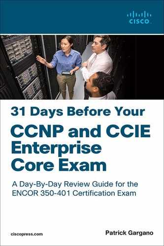
The left side of Figure 9-2 shows that when an inbound email arrives (step 1), the Cisco Adaptive Security Appliance (ASA) intercepts that email and forwards it to the ESA (step 2), where the malware is denied. The right of the figure shows that an email that does not contain malware is permitted to reach the intended receiver (step 3).
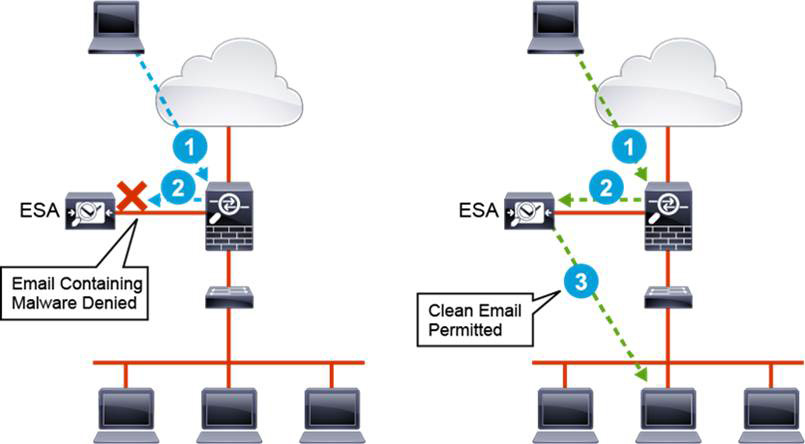
Figure 9-2 Cisco Email Security Appliance Filtering
The Cisco WSA provides secure web access, content security, and threat mitigation for web services. In addition to helping to secure and control web traffic, the Cisco WSA provides the following forms of protection:
• Advanced malware protection
• Application visibility and control
• Insightful reporting
• Secure mobility
The left side of Figure 9-3 shows a user’s request for a gambling website (step 1) being forwarded to the WSA for inspection (step 2). The WSA blocks the user request and returns a web page informing the user of the policy violation (step 3).
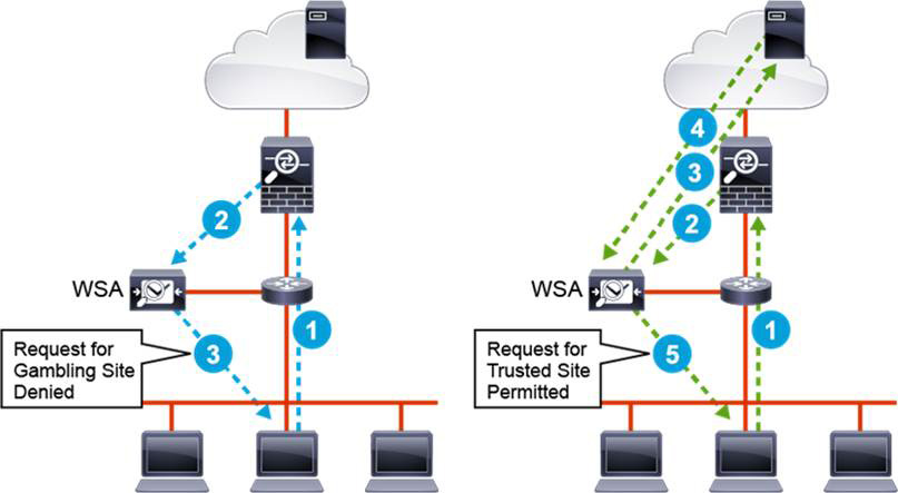
Figure 9-3 Cisco Web Security Appliance Filtering
The right side of the figure shows a user’s request for a permitted website (step 1) being forwarded to the WSA (step 2). The WSA proxies the user’s request to the website (step 3), and the web page is returned to the WSA (step 4). The WSA can then check the content for malware and forward the verified content to the user (Step 5).
Endpoint Security
The term endpoint security refers to protecting an endpoint device, such as a desktop computer, laptop, tablet, or smartphone. The term also refers to verifying the user, the device, and the device state to protect the network.
Traditionally, endpoint security has relied on three types of software installed on endpoints to protect endpoint devices and the data that resides on them:
• Personal firewalls: This software protects only the device on which it is installed. A personal firewall may have the ability to block applications, files, and services, and it may also provide intrusion detection services.
• Antivirus software: This software prevents and removes computer viruses and other types of malicious software. Computer viruses spread from one computer to another, leaving infections as they travel. They can damage data or software or even cause DoS conditions.
• Antispyware software: This software detects and removes spyware. Spyware displays advertisements and tracks information on an endpoint device without the user’s consent. Spyware can make changes to the endpoint device without the user’s consent and can damage the device. Both antispyware and antivirus software must be updated frequently to remain effective.
Today’s attackers have the resources, expertise, and persistence to compromise any organization if given enough time. Traditional personal firewalls, antivirus, and antispyware no longer work against these attackers. Defending against today's targeted, persistent malware attacks is a bigger problem than a single point-in-time control or product can effectively address on its own. Therefore, the process of handling malware has evolved. Advanced malware protection uses integrated controls and a continuous process to detect, confirm, track, analyze, and remediate threats before, during, and after an attack.
Centralized Endpoint Policy Enforcement
The requirements of an organization for endpoint protection software should be defined in the organization’s security policy. Optimally, systems should be in place to enforce those policies as systems connect to the network.
The Cisco AnyConnect Secure Mobility Client is a multifaceted endpoint software product. It provides VPN access through Secure Sockets Layer (SSL) and also offers enhanced security through various built-in modules, such as Cisco Network Access Manager, Cisco AnyConnect ISE Agent, and Cisco AnyConnect Web Security Client. Cisco AnyConnect is available across a broad set of platforms, including Windows, macOS, Linux, iOS, and Android.
Cisco AnyConnect offers an ASA Posture module and an Identity Services Engine (ISE) Posture module, as illustrated in Figure 9-4. Both enable Cisco AnyConnect to assess compliance on endpoints for things like operating system version, antivirus software, and antispyware software installed on the endpoint. You can use these tools to restrict network access until the endpoint is compliant. The ASA Posture module is used with Cisco ASA to enforce policy for endpoints that connect to the network via remote-access VPN. The ISE posture module is used with Cisco ISE to enforce policy for internal endpoints that connect via either wired or wireless technology.

Figure 9-4 Cisco AnyConnect Posture Assessment
The two Posture modules perform similar functions but in different ways. The ISE Posture module performs a client-side evaluation. The AnyConnect client receives the posture requirement policy from ISE, performs the posture data collection, compares the results against the policy, and sends the assessment results back to ISE. Even though ISE determines whether the endpoint is compliant, it relies on how the endpoint evaluates the policy. In contrast, the ASA Posture module performs server-side evaluation, in which the ASA asks only for a list of endpoint attributes. AnyConnect gathers the attribute values and sends them back to the ASA. The ASA then evaluates the values to determine whether the client is allowed to create a remote-access connection to the network.
The lists of attributes that can be examined by the two Posture modules differ, but both modules have the ability to examine an endpoint for operating system type version, antivirus software, and antispyware applications. The ASA Posture module also has the ability to examine personal firewall software. The significance of personal firewall software increases when the endpoint is outside the protective elements of the enterprise network.
Both systems have the ability to allow connections for compliant endpoints and reject connectivity for noncompliant endpoints. They also have remediation capacities, but the two systems use different strategies. Remediation with the ASA is limited to working with the software that is already installed on the endpoint. The remediation capabilities include the ability to enable software that has been disabled, force updates for antivirus and antispyware software, and push firewall policy to the personal firewall software. Remediation with the ASA requires the advanced endpoint assessment license to be installed on the appliance. Remediation with ISE is based on quarantining the endpoint. Instead of allowing normal connectivity for the noncompliant endpoint, the endpoint is allowed very limited connectivity. The limited connectivity includes the ability to reach servers from which the required software can be obtained. After the required software has been properly installed, the Posture module is executed again. If the endpoint has reached a state of compliance, it is allowed normal access to the network.
Cisco AMP for Endpoints
Due to the nature of malware threats in current networking environments, even the best commercial products for malware detection can realistically achieve about 40% success in detection. Most enterprises implement multiple layers of protection, so malware that makes it to an endpoint defeats all the safeguards. This means that to effectively deal with malware, you must assume that at some point, the malware will make its way into your networks, and it may potentially persist for long periods of time before it is detected and acted upon.
With malware, endpoints must be protected before, during, and after attacks. Cisco AMP for Endpoints (see Figure 9-5) goes beyond point-in-time detection to provide the level of visibility and control you need to stop advanced threats that are missed by other security layers. It provides that protection across the attack continuum: before, during, and after an attack. Cisco AMP for Endpoints is an intelligent, enterprise-class advanced malware analysis and protection solution based on a telemetry model that uses big data, continuous analysis, and advanced analytics to detect, track, analyze, control, and block advanced malware outbreaks across all endpoints: PCs, Macs, mobile devices, and virtual systems.

Figure 9-5 Cisco AMP for Endpoints
Cisco AMP for Endpoints provides cloud-based detection of malware through the Cisco Collective Security Intelligence Cloud, which is a powerful alternative to traditional malware detection and that offers these features:
• Rapid detection of known malware
• Use of cloud resources to test files with unknown dispositions
• Use of machine learning techniques to constantly keep itself up to date
AMP for Endpoints gives you a historical perspective so that you can see, over time, the actions that files have performed on a system. You can trace an infection and identify the root cause. The historical perspective gives you visibility into the following:
• File trajectory: Shows the hosts where files were seen
• Device trajectory: Shows the actions that files performed on a given host
With AMP for Endpoints you can block malicious network connections based on security intelligence feeds (IP reputation) and custom IP blacklists.
Because malware that employs stealth techniques to hide its true intent may not initially be identified as malicious, the machine learning and behavior monitoring engines in the cloud may change the disposition of a file from "unknown" to "malicious." This is known as retrospective alerting, or cloud recall. It means that Cisco AMP for Endpoints can go back to the systems where a file was previously seen, alert the client to the changed disposition, and quarantine the file.
You can deploy simple custom detections or advanced custom detections, in which you can create your own signatures for malware detection. You can create groups of hosts that can run different policies to suit the detection needs of specific environments. Cisco AMP for Endpoints also provides robust reporting tools.
As illustrated in Figure 9-6, Cisco AMP for Endpoints consists of the following elements:
• Cisco Collective Security Intelligence Cloud: This is where the various detection and analytics engines reside.
• Client Connector: This is the component that runs on the endpoints. It communicates with the cloud to send information about files and to receive file disposition information.
• Cisco AMP for Endpoints: You can install this application on PCs, Macs, and mobile devices to communicate with the cloud for detection of mobile malware. Cisco AMP for Endpoints is supported on various Android, Windows, Linux, and Apple operating systems.
• AMP for Networks: This application gives Firepower devices the ability to query the cloud to obtain file disposition information on files that are detected by the Firepower device.

Figure 9-6 Cisco AMP for Endpoints Elements
Firewall Concepts
A firewall is a system that enforces an access control policy between two or more security zones. There are several types of firewalls, but all firewalls should have the following properties:
• The firewall itself must be resistant to attack; otherwise, it would allow an attacker to disable the firewall or change its access rules.
• All traffic between security domains must flow through the firewall to prevent backdoor connections that could be used to bypass the firewall, violating the network access policy.
• A firewall must have traffic-filtering capabilities.
Firewalls commonly control access between security zones based on packet source and destination IP address and port.
A firewall can be a hardware appliance or a software program. Although firewalls can be placed in various locations within a network (including on endpoints), they are typically placed at the Internet edge, where they provide vital security. Firewall threat controls should be implemented at least at the most exposed and critical parts of enterprise networks. The Internet edge is the network infrastructure that provides connectivity to the Internet and acts as the gateway for the enterprise to the rest of the cyberspace. Because it is a public-facing network infrastructure, it is particularly exposed to a large array of external threats.
Firewalls are also often used to protect data centers. A data center houses most of the critical applications and data for an enterprise. The data center is primarily inward facing, and most clients are on the internal network. The intranet data center is subject to external threats but must also be guarded against threat sources inside the network perimeter.
Many firewalls also provide a suite of additional services, such as Network Address Translation (NAT) and multiple security zones. Another important service that firewalls frequently provide is VPN termination.
Firewall products have evolved to meet the needs of today's networks. From simple perimeter security with access control lists (ACLs) based on IP addresses and ports, firewalls have evolved to offer some advanced security services. The hard outer shell that firewalls provided in the past has been superseded by security capabilities that are integrated into the very fiber of the network to defend against today’s multi-vector and persistent threats. To handle the current threatscape, next-generation firewalls (NGFWs) are needed.
In addition to standard first-generation firewall capabilities, NGFWs have capabilities such as the following:
• Tight integration of security functions to provide highly effective threat and advanced malware protection
• Implementation of policies based on application visibility instead of transport protocols and ports
• Provision of URL filtering and other controls over web traffic
• Provision of actionable indications of compromise to identify malware activity
• Comprehensive network visibility
• Reduce complexity
• Smooth integration and with other security solutions
In a network, a firewall is intended to control what passes from one security zone to another. If a system is compromised in one zone, firewalls help to contain the attack to within that zone. In addition, within a network, firewalls also have the job of preventing undesirable access in the first place.
Consider the following common deployment scenario for a firewall using three zones, as illustrated in Figure 9-7:
• Inside: A private, trusted network
• Outside: The public, untrusted Internet
• Demilitarized zone (DMZ): A zone containing servers that are accessible by the public Internet

Figure 9-7 Firewall Zones
While every deployment has its own unique requirements, some policies are commonly implemented in most deployments. For example, connections from systems on the outside to systems on the inside are forbidden. Connections from the inside to the outside, on the other hand, are generally permitted. However, there may be limitations on the application protocols that are allowed from the inside to the outside. For connectivity from the outside to the DMZ, what is allowed is strictly defined. Access is only allowed to the specific ports on specific servers based on the services that are intended to be provided by the server. Also, it is common to be very restrictive in terms of the connections that can be made from servers on the DMZ to systems in other zones. If a server on the DMZ is compromised by an attacker, the compromised server should not be allowed to be used as a stepping stone to the inside or to launch attacks against other systems on the outside.
Next-Generation Firewalls
Historically, the firewall has been the cornerstone of an organization’s network security strategy. It was designed based on the notion that internal traffic and users are inherently trustworthy, and external traffic isn’t, thus creating a trust boundary—or perimeter—between networks. This network perimeter became the logical security control point to protect the entire organization: the network, data, users, and devices. All network traffic, whether originating from the headquarters, a data center, or a remote worker, was funneled through this single control point. Since then, the ways networks are deployed and operate have changed. Many business-critical applications have moved from data centers and premises-based networks to the cloud. Branch offices are now connecting directly to the Internet, and users are accessing resources from their personal devices everywhere. NGFWs provide features such as the following to defend networks against increasingly sophisticated threats:
• URL filtering: URL filtering involves moving the most commonly used proxy server function into the firewall itself and may take advantage of URL classification and website reputation scores.
• Application visibility and control: This feature recognizes applications by analyzing data streams instead of looking at transport layer port numbers. For example, applications like Skype that are capable of hopping from one port to another can be recognized. Another example is not only recognizing Facebook but recognizing gaming within Facebook.
• Context awareness: Who is connecting, to what, from where, using which device, at what time? Policy can be defined, for example, to allow members of the marketing team to access Facebook for marketing purposes, but even they may not be allowed to access Facebook games. Also, what users can access via their corporate managed laptops and what they can access via their personal mobile phones may differ.
• Intrusion prevention system: Intrusion prevention has traditionally been handled by separate systems but can now be integrated directly into a firewall appliance, and it can be made even more powerful by utilizing the contextual awareness that is integrated into the NGFW.
• Advanced malware protection: This feature can provide detection, blocking, tracking, analysis, and remediation.
TrustSec
One of the limiting factors in traditional network security is that security is based on the Layer 3 addresses assigned to the endpoints. In most networks, the identity or user of the endpoint is a better indication of the trustworthiness of that endpoint. By abstracting the network addressing and using the identity associated with the endpoint for security, Cisco TrustSec makes securing the network an easier task for a network security engineer.
Cisco TrustSec simplifies the provisioning and management of secure access to network services and applications. Unlike access control mechanisms that are based on network topology, Cisco TrustSec defines policies using logical policy groupings, so secure access is consistently maintained even as resources are moved in mobile and virtualized networks. Decoupling access entitlements from IP addresses and VLANs simplifies security policy maintenance tasks, lowers operational costs, and allows common access policies to be applied to wired, wireless, and VPN access consistently.
Cisco TrustSec encompasses Security Group Tags (SGTs) and the Institute for Electrical and Electronics Engineers (IEEE) standard MAC Security (MACsec). Note that SGT tags are referred to as Scalable Group Tags in Cisco Software-Defined Access (SD-Access).
Cisco TrustSec classification, transport, and policy enforcement functions are embedded in Cisco switching, routing, wireless LAN, and firewall products. By classifying traffic based on the contextual identity of an endpoint instead of its source IP address, Cisco TrustSec enables more flexible access controls for dynamic networking environments and data centers. The features that are associated with SGTs on the network devices can be grouped into three categories:
• Classification: Classification is the assignment of an SGT to an IP address. This can be accomplished either dynamically or statically. Generally, dynamic classification is done at the access layer, and static classification is done in the data center. Dynamic classification uses the rich context data available to Cisco ISE for making policy decisions. Dynamic classification can be done using IEEE 802.1X, MAC Authentication Bypass, or Web Authentication. Static classification is generally configured on the switch to which servers are attached. Static options and configuration syntax vary by switching platform and operating system version. Options for static classification include the mapping of an IP address, a VLAN, or a port to an SGT. Also, Cisco ISE can centrally store a database of IP addresses and their corresponding SGTs. Compatible devices can download the centrally managed mappings from Cisco ISE.
• Transport: Security group mappings follow the traffic through the network. This can be accomplished either through inline tagging or use of SGT Exchange Protocol (SXP). With inline tagging, the SGT is embedded in the Ethernet frame header. Not all network devices support inline tagging. SXP is used to transport SGT mappings across devices that do not support inline tagging.
• Enforcement: Enforcement means implementing permit or deny policy decisions based on the source and destination SGTs. This can be accomplished with security group ACLs (SGACLs) on switching platforms and security group firewalls (SGFWs) on routing and firewall platforms.
MACsec provides secure communication on wired LANs. When MACsec is used to secure the communication between endpoints on a LAN, the packets on the wire are encrypted using symmetric key cryptography, so that communication cannot be monitored or altered on the wire. When MACsec is used with Security Group Tags, it provides protection for the tag as well as the data contained in the payload of the frame.
At the point of network access, a Cisco TrustSec policy group called an SGT is assigned to an endpoint, as shown in Figure 9-8. This is done considering any of a rich set of attributes (context), including the endpoint’s user, device type, posture status, and location attributes. The SGT is used to specify the endpoint access entitlements. All traffic from the endpoint carries the assigned SGT. Switches, routers, and firewalls use the SGT to make forwarding decisions. Because SGT assignments can denote business roles and functions, Cisco TrustSec controls can be defined in terms of business needs and not underlying networking detail. SGTs can span physical locations. SGTs are independent of IP address, subnet, or VLAN. SGACL-capable switches can implement access controls between systems with the same or different SGT values, even if they are on the same VLAN.

Figure 9-8 Cisco TrustSec SGT Processing
Instead of managing access control on large numbers of prefixed IP addresses, access control is managed across a relatively small number of relevant security group classifications. SGACLs define which services are accessible between two security groups. A simple matrix assigns all SGACLs to source and destination SGT pairs. One matrix provides all policy for the entire TrustSec domain. In the example shown in Figure 9-8, traffic using an SGT value of 3 is permitted access to the IT server (SGT 13) according to the SGACL configured on the data center switch.
The frames that enter the Cisco TrustSec domain are marked using an SGT. This is a unique 16-bit tag that represents the unique role of the traffic source in the network. The tag can be thought of as a privilege identifier of the source user, device, or entity. The tagging decisions can be either dynamic or static.
Dynamic tagging can be deployed with IEEE 802.1X authentication, MAC Authentication Bypass (MAB), or Web Authentication. In these access methods, Cisco ISE can push an SGT to the network access device (NAD) to be inserted into the client traffic. The SGT is applied as a permission in the authorization policy rules. This permission can be assigned in addition to or instead of an authorization profile.
Static tagging can be configured in Cisco ISE and then downloaded to a NAD, or it can be configured directly on a NAD. Examples of static tagging include a mapping of an IP host or subnet to an SGT and the mapping of a VLAN to an SGT. Numerous other options exist, with varying support depending on the device platforms and software versions.
Because the SGT contains the security group of the source, the tag can be referred to as the source SGT. The destination device is also assigned to a security group (the destination SG), which can be referred to for simplicity as the DGT, although the actual Cisco TrustSec packet tag does not contain the security group number of the destination device. The DGT comes into play only during enforcement.
Inline SGT Transport
SGTs can be transported inline between two capable devices that are configured for Cisco TrustSec on their connecting interfaces. Using this method, the sending device imposes the SGT in the outgoing frame Ethernet header on egress, as illustrated in Figure 9-9. The receiving device reads and processes the SGT from the Ethernet header on ingress.
Figure 9-9 Cisco Meta Data (CMD) Header
The SGT is embedded in the Cisco Meta Data (CMD) header. The SGT is carried in a 16-bit field in the CMD header. Frames crossing a link between capable switches can also be protected with MACsec. A MACsec-protected frame puts the other tags and the data contained within the frame between the MACsec header and the Integrity Check Value (ICV) field. These tags and the frame data are all protected by MACsec encryption and authentication. The increase of the MTU size that results from both 802.1AE and Cisco TrustSec overhead is approximately 40 bytes.
Using SGACLs, you can control access policies based on source and destination SGTs. Policy enforcement in the Cisco TrustSec domain is represented by a permissions matrix, with source security group numbers on one axis and destination security group numbers on the other axis. Each cell in the body of the matrix can contain an ordered list of SGACLs. Each SGACL specifies the permissions that should be applied to packets originating from the source security group and destined for the destination security group. It is important to note that the source and destinations are specified in the permissions matrix and not in the SGACL. Consider, for example, the SGACL entry deny TCP DST eq 21. The entry that specifies access from the source to the destination TCP port 21 is denied. There is no specification of the SGTs or DGTs in the SGACL. It is the application of the SGACL in the permissions matrix that specifies the source and destination security groups. It is also important to understand that the same SGACL can be applied to multiple source and destination security group pairs within the permissions matrix.
By applying access control between pairs of security groups, Cisco TrustSec achieves role-based, topology-independent access control within the network. Changes in network topology do not normally require a change in SGACL-based security policy. Some care must be taken to ensure the proper classification of new network resources, but the access policy based on business-relevant security groups does not change. If changes do require the creation of a new security group, then the permissions matrix increases in size by one row and one column. Policy for the new cells is defined centrally in Cisco ISE and dynamically deployed to all SGACL enforcement points.
Using role-based permissions greatly reduces the size of ACLs and simplifies their maintenance. With Cisco TrustSec, the number of ACEs configured is determined by the number of permissions specified, resulting in a much smaller number of ACEs than in a traditional IP network. Also, only a single copy of an SGACL needs to reside in the TCAM of a device, regardless of how many times the SGACL is used. The use of SGACLs in Cisco TrustSec typically results in more efficient use of TCAM resources compared with traditional ACLs.
Figure 9-10 shows the Cisco TrustSec Policy configuration page in Cisco ISE. Notice that the sources and destinations are groups, such as Employees and Contractors, and the actual SGACLs are placed in the production matrix to permit and deny certain types of traffic.
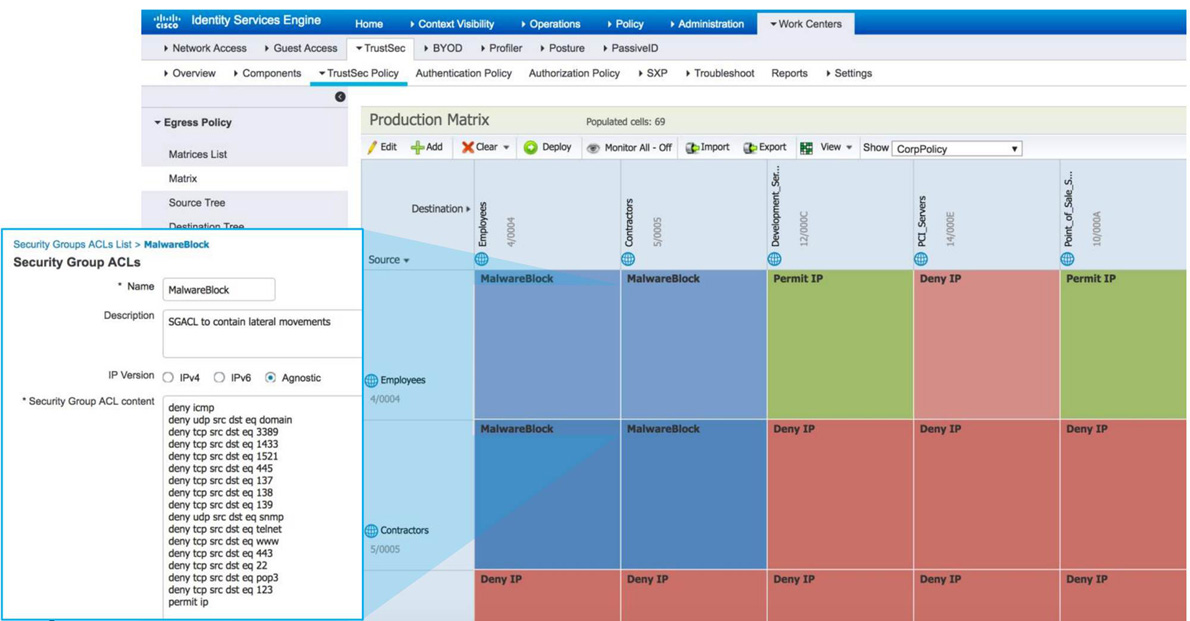
Figure 9-10 Cisco ISE TrustSec Configuration Example
Security Group Firewall
Instead of using SGACLs, Cisco ASA and select routing platforms enforce TrustSec policy by using SGFW features. Whereas SGACL policy is centrally managed from Cisco ISE, SGFW policy is managed independently on the device configurations. SGFW capabilities were integrated into the ASA rule policy in Version 9.0 and into the Cisco IOS zone-based firewall feature in Version 15.2. Figure 9-11 illustrates the use of security group data in an access control entry on the ASA, both from Cisco ASDM and from the CLI. In this example, FTP packets sourced from SGT 3 and destined to SGT 4 are denied. All other traffic is permitted.
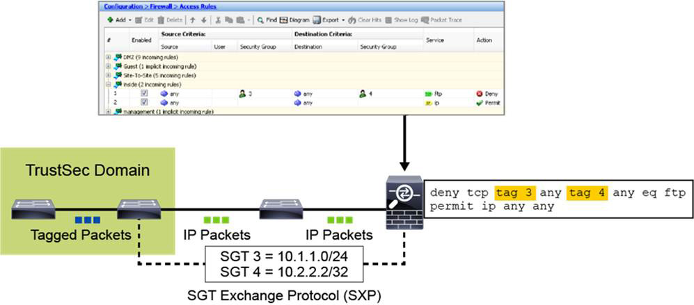
Figure 9-11 Cisco ASA TrustSec SGFW Configuration Example
In the Cisco IOS zone-based policy firewall, security group statements can be used in class-map definitions. In both Cisco ASA and Cisco IOS zone-based policy firewall, security group information can be used with other traffic specification mechanisms, such as source and destination IP addresses, protocols, and port numbers. One compelling use case on the Cisco ASA is security group information used to define traffic that should be sent to a virtual IPS sensor resident in the ASA for appropriate deep packet inspection.
Cisco ASA security policy is configured with ACLs. You can create ACLs on the Cisco ASA that contain SGTs or security group names. The ASA enforces policies based on security group names or SGTs if the ASA has a security group table to map security group names to SGTs and an SGT-to-IP mapping exists.
MACsec
MAC Security (MACsec) is an IEEE 802.1AE standards-based Layer 2 hop-by-hop encryption technology that provides data confidentiality and integrity for media access–independent protocols.
MACsec provides MAC-layer encryption over wired networks. It uses out-of-band methods for encryption keying. Required session keys are provided and encryption keys are managed using the MACsec Key Agreement (MKA) protocol. After successful authentication, MKA and MACsec are implemented using the 802.1x Extensible Authentication Protocol (EAP) framework. Only host-facing links (links between network access devices and endpoint devices such as a PC or an IP phone) can be secured using MACsec.
Depending on the policy assigned to the client connected to a secured port, a switch can accept either MACsec or non-MACsec frames. An Integrity Check Value (ICV) field encrypts and protects MACsec frames. Frames received at the switch from the client are decrypted, and the correct ICV is calculated using the session keys provided by MKA. If the calculated ICV does not match the ICV within the frame, the frame is dropped. Any frames that the switch sends to the client over the secured port are also encrypted and have an ICV field added.
Encryption keys used by the underlying MACsec protocol are managed by the MKA protocol. The MKA protocol extends 802.1x to allow peer discovery with confirmation of mutual authentication and sharing of MACsec secret keys to protect data exchanged by the peers.
The EAP framework implements MKA as a newly defined EAP over LAN (EAPoL) packet, as shown in Figure 9-12. EAP authentication produces a master session key (MSK) that is shared by both partners in the data exchange. Entering the EAP session ID generates a secure connectivity association key name (CKN). Because the switch is the authenticator, it is also the key server, generating a random 128-bit secure association key (SAK), which it sends it to the client partner. The client is never a key server and can only interact with a single MKA entity, the key server.

Figure 9-12 MACsec Frame Format
The packet body in an EAPoL protocol data unit (PDU) is referred to as a MACsec Key Agreement PDU (MKPDU). MKA sessions and participants are deleted when the MKA lifetime (6 seconds) passes with no MKPDU received from a participant. For example, if a client disconnects, the participant on the switch continues to operate MKA until 6 seconds have elapsed after the last MKPDU is received from the client.
Identity Management
Instead of describing a specific product, Cisco Identity-Based Networking Services (IBNS) is a suite of services that are embedded in Cisco Catalyst switches and Cisco WLCs. Cisco IBNS supports a wide range of authentication options in which order and priority are configurable for additional flexibility. Cisco ISE uses infrastructure services provided by switches and WLCs to allow you to implement IBNS features including the following:
• 802.1X for managed devices and users
• MAC Authentication Bypass (MAB) for unmanaged or non-802.1X devices
• Web Authentication for guests or non-802.1X users
IBNS promotes authentication to access the network. Authentication serves as the basis for differentiating users and/or devices, providing varying levels of access to networked resources based on corporate access policy, as shown in Figure 9-13.
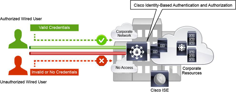
Figure 9-13 Cisco Identity-Based Networking Services (IBNS)
The foundation for IBNS is IEEE 802.1X, a port-based authentication and access control protocol, which can be applied at a physical switch port on a wired network or on a wireless local-area network (WLAN) on Cisco Wireless LAN Controller.
In both wired and wireless domains, clients require the installation of a Cisco 802.1X supplicant and the configuration of a native operating system supplicant or, in the case of Linux clients, the installation of an open-source supplicant.
Wireless users generally expect that they will need to authenticate before being granted access to a corporate network. As a result, populations of wireless users are good candidates for initial Cisco IBNS deployments.
If a user or a device connecting to a network lacks the supplicant, the user or the device can authenticate using MAB or Web Authentication. Examples are guest users and simple devices, such as printers or IP cameras.
We discussed 802.1X and WebAuth in terms of wireless access on Day 10, “Wireless Client Roaming and Authentication.” The next sections quickly review these concepts, focusing primarily on wired access.
802.1X for Wired and Wireless Endpoint Authentication
IEEE 802.1X provides port-based authentication. Network devices have the following roles, as shown in Figure 9-14:
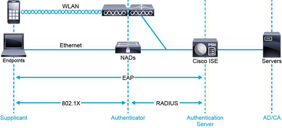
Figure 9-14 802.1X Devices and Roles
• Supplicant: This is an endpoint 802.1X-compliant software service that communicates with network access device (NAD) authenticators to request network access.
• Authenticator: The authenticator controls access to the network, based on client authentication status. The objective is for endpoints to authenticate to the authentication server via EAP. NAD authenticators act as intermediaries (proxies) between client and authentication server. They communicate with endpoint supplicants via 802.1X to request identity information. Then they communicate with the authentication server via RADIUS to verify that information. They relay authentication server responses back to the client. The authenticator acts as a RADIUS client, encapsulating and decapsulating EAP frames.
• Authentication server: This role performs client authentication. The authentication server validates client identity and notifies NAD authenticators of client authorization status. Because the authenticator acts as the proxy, the authentication service is transparent to the client. Cisco ISE acts as the authentication server. Credentials and certificates can be offloaded to Active Directory (via LDAP) or certificate authority servers.
When a switch receives EAPoL packets, it frames and relays them to the authentication server. The frame’s Ethernet header is stripped and then re-encapsulated into RADIUS format. The EAP fields are not modified during encapsulation, and the authentication server must support EAP in the native frame format.
When the authenticator receives EAP frames from the authentication server, the frame header is removed. The EAP frame is then encapsulated using EAPoL and sent to the supplicant.
802.1X Message Flow
Figure 9-15 illustrates the 802.1X message exchange process. Authentication can be initiated by the supplicant or the authenticator. The authenticator initiates authentication when the link state changes from down to up or periodically, as long as the port remains up and unauthenticated.
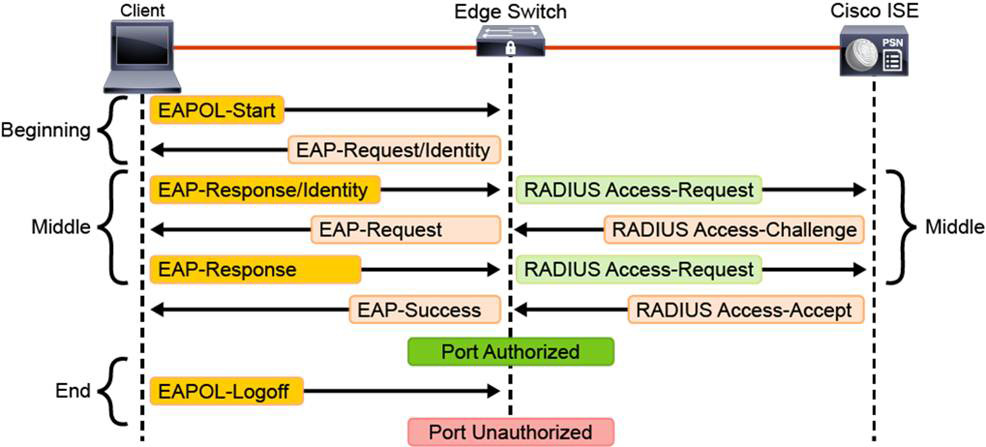
Figure 9-15 802.1X Message Flow
The authenticator sends an EAP request or identity frame to request client identity. The supplicant receives the frame and sends an EAP response or identity frame. However, if during bootup the supplicant does not receive an EAP request or identity frame, it can initiate authentication. The supplicant sends an EAPoL start frame, which prompts the authenticator to request client identity.
When the supplicant provides its identity, the authenticator begins its role as the intermediary. The supplicant passes EAP frames between supplicant and authentication server until authentication succeeds or fails. If authentication succeeds, the authenticator port is authorized.
The specific exchange of EAP frames varies depending on the authentication method. Figure 9-15 depicts the three phases of the 802.1X authentication process: the beginning, the middle, and the end.
802.1X Authorization
As a result of successful authentication, Cisco ISE can perform per-user and per-group network authorization. The 802.1X framework provides authentication and authorization of clients that seek network access. The authorization features include the following:
• VLAN assignment: An authentication server can associate a VLAN with a particular user or group. Thus, the switch can dynamically assign a VLAN for an authenticated user. VLAN assignment is appropriate if the desired access control method is based on different VLANs (with routed access control lists [ACLs] or a firewall system that is configured egress to the VLANs). It provides strong access control and auditing. After successful 802.1X/EAP authentication, the user can be authorized to be on a specific VLAN. This dynamic VLAN is configured on the Cisco ISE RADIUS service and communicated in a RADIUS Access-Accept message. While typically used to assign a VLAN upon successful authentication, this process can also be used when authentication fails.
• ACL assignment: The authentication server associates an ACL with a particular user or group. It then instructs the NAD to dynamically assign the ACL to the user session. This mechanism provides very granular access control, right down to the port level. ACLs can either be named or dynamically downloaded. Named ACLs provide differentiated access for wireless users. Named ACLs are configured locally on the WLC. You merely reference the ACL in a Cisco ISE authorization policy. Of course, it is vital that the name you specify in Cisco ISE matches the name of the ACL defined in the WLC. Downloadable ACLs (dACLs) can provide different levels of access to 802.1X-authenticated users. The RADIUS server authenticates 802.1X-connected users. Based on user identity, it retrieves ACL attributes and sends them to the switch. The switch applies attributes to the 802.1X port during the user session.
• Time-based access: The authentication server controls each user’s allowed access days and times.
• Security group access (SGTs): Security group access provides topology-independent, scalable access control. With security group access, the ingress switches classify data traffic for a particular role and tag the traffic with SGTs. The egress network devices evaluate the SGTs and filter packets by applying appropriate security group ACLs.
MAC Authentication Bypass
Many devices connected to the enterprise network may not support 802.1X authentication. These devices should not be exempt from authenticating before being allowed to access the network. MAC Authentication Bypass (MAB) is an alternative method that can be used when devices do not support other authentication methods.
Static MAC authentication, also known as MAB, uses a MAC address for both the username and password. This authentication is the most basic form of authentication in deployments because many devices either do not, or cannot, support 802.1X. Because MAC addresses are easily spoofed, they provide a relatively weak form of authentication, but they are a good first step for device identification.
MAB enables port-based access control by using the MAC address of the endpoint. Before MAB, the identity of the endpoint is unknown, and all traffic is blocked. The switch examines a single frame to learn and authenticate the source MAC address. After MAB succeeds and the identity of the endpoint is known, it allows all traffic from that endpoint. The switch performs source MAC address filtering to help ensure that only the MAB-authenticated endpoint is allowed to send traffic. This process is illustrated in Figure 9-16. Before MAB, all device traffic is dropped until the switch is able to authenticate the MAC address of the device. Once authenticated, traffic is authorized through the switch port.

Figure 9-16 MAC Authentication Bypass: Before and After
From the switch's perspective, the authentication session begins when the switch detects a link up on a port. The switch initiates authentication by sending an EAP Request-Identity message to the endpoint. If the switch does not receive a response, the switch retransmits the request periodically. If no response is received after the maximum number of retries, the switch lets IEEE 802.1X time out and proceed to MAB.
During the MAC address learning stage, the switch begins MAB by opening the port to accept a single packet from which it will learn the source MAC address of the endpoint. Packets sent before the port has fallen back to MAB (that is, during the IEEE 802.1X timeout phase) are discarded immediately and cannot be used to learn the MAC address.
A switch can use almost any Layer 2 and 3 packets to learn MAC addresses, with the exception of bridging frames such as Cisco Discovery Protocol, Link Layer Discovery Protocol (LLDP), Spanning Tree Protocol, and Dynamic Trunking Protocol (DTP).
After a switch learns the source MAC address, it discards the packet. Then the switch crafts a RADIUS Access-Request packet. If the MAC address is valid, the RADIUS server returns a RADIUS Access-Accept message. This message indicates to the switch that the endpoint should be allowed access to the port. Optionally, the RADIUS server may include dynamic network access policy instructions (for example, a dynamic VLAN or access control list [ACL]) in the Access-Accept message. In the absence of dynamic policy instructions, the switch simply opens the port. No further authentication methods are tried if MAB succeeds.
If the MAC address is not valid or is not allowed to access the network for policy reasons, the RADIUS server returns a RADIUS Access-Reject message. This message indicates to the switch that the endpoint should not be allowed access to the port, based on the MAC address.
Web Authentication
When guests, contractors, or employees connect to the enterprise network, they may not be able to use 802.1X authentication. An identity-based authentication that can be used in these cases is Web Authentication (WebAuth).
As discussed on Day 10, WebAuth is typically used for guest network access via Hypertext Transfer Protocol (HTTP) or HTTP Secure (HTTPS) authentication. WebAuth allows endpoints either without an 802.1X supplicant or with an 802.1X supplicant that does not authenticate to authenticate by another means.
For example, WebAuth can be used as a method of last resort when an 802.1X supplicant is not installed or when the supplicant is misconfigured or nonfunctional. If the 802.1X supplicant is nonfunctional, WebAuth could prompt the user for credentials and still provide network access. WebAuth may also be used for guest users who have an 802.1X supplicant but lack a user account in the appropriate identity store.
WebAuth can be implemented in both wired and wireless environments. With WebAuth, users connect to the network, and their initial attempt to access a URL is automatically redirected to an authentication web page.
When wired or wireless guest users first connect, they have limited access. This can be defined in Cisco ISE through a dACL or a VLAN on a switch or the named ACL on a wireless LAN controller (WLC). At this initial stage, the authorization assignment permits only WebAuth traffic. All other traffic is redirected to the WebAuth service.
To gain full access, guest users browse via HTTP or HTTPS to a DNS-resolvable website, such as http://guests.cisco.com. The NAD intercepts the HTTP/HTTPS request and redirects it to the guest user login portal. After successful authentication, the user is assigned an appropriate authorization profile. This profile allows appropriate access to enterprise resources.
WebAuth using Cisco ISE supports five scenarios:
• NAD with Central WebAuth: This scenario applies to wired and wireless network access devices. In this scenario, the user is redirected to the Cisco ISE web service for authentication. The authentication is performed on Cisco ISE. Cisco ISE sends a change of authorization (CoA) to the NAD after authentication.
• WLC with Local WebAuth: In this scenario, the wireless user logs in and is directed to the WLC. The WLC then redirects the user to the guest portal. The guest portal prompts the user for a username and a password and requires the acceptance of an acceptable use policy (AUP), as shown in Figure 9-17. When this process is complete, the user’s browser is redirected back to the WLC to log in again. The WLC authenticates the user via RADIUS and then redirects the client browser to the original destination.
• Wired NAD with Local WebAuth: In this scenario, the guest user login portal redirects the wired guest user login to the switch. The login request is in the form of an HTTPS URL that is posted to the switch and contains the user credentials. The switch receives the user login request and authenticates the user through a RADIUS server that points to Cisco ISE.
• Device registration WebAuth: In this scenario, the user connects to the network with a wireless connection. An initial MAB request is sent to the Cisco ISE node. If the user MAC address is not in the endpoint identity store, Cisco ISE responds with a URL redirection authorization profile. The URL redirection presents the user with an AUP acceptance page when the user attempts to browse to any URL.
• Cisco EasyConnect: The Cisco ISE EasyConnect feature enables enterprises to implement identity-based network access without the need for 802.1X. No supplicants or supplicant configurations are needed on endpoints. An EasyConnect session, which is similar to the WebAuth flow, starts with MAP. ISE learns about an endpoint’s location, MAC address, and IP address via an initial MAB session. This initial MAB session is authorized with limited access from ISE to enable a Windows Active Directory–managed endpoint to perform a Windows domain login. Upon successful domain login, the user ID-to-IP address mapping from the Active Directory (AD) domain controller is sent to ISE and merged with the initial MAB session. After the user ID and its AD group membership are resolved, ISE changes the authorization to permit additional access.
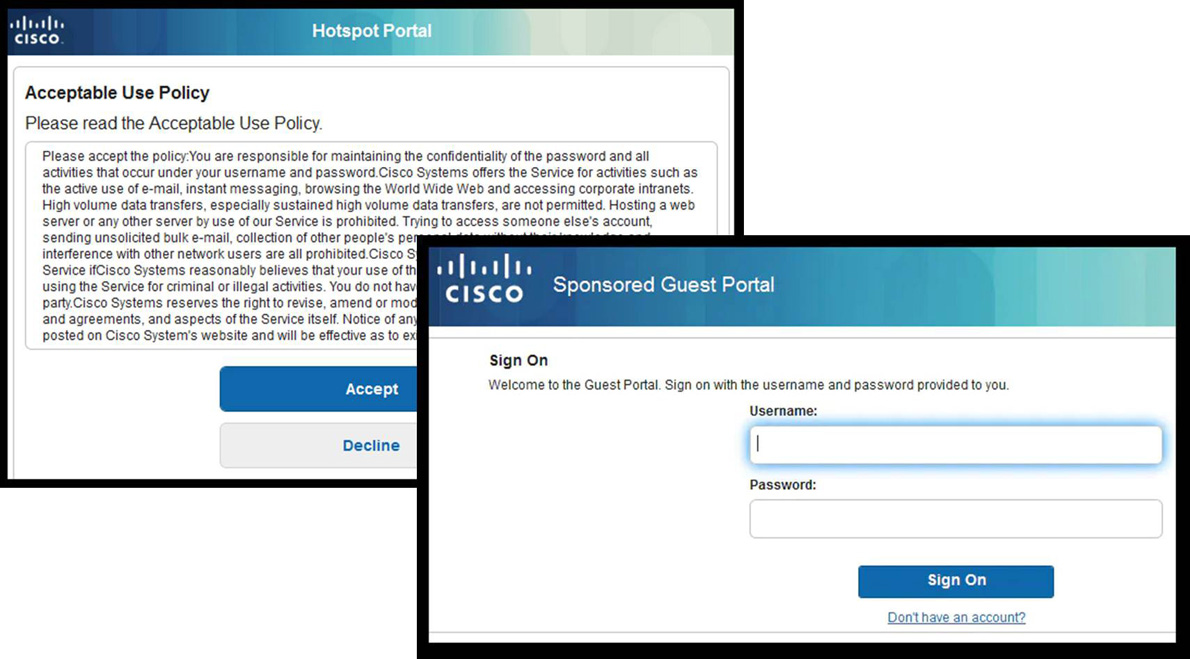
Figure 9-17 WebAuth Login and AUP Screens
Study Resources
For today’s exam topics, refer to the following resources for more study.
