Day 22. First-Hop Redundancy Protocols
ENCOR 350-401 Exam Topics
• Explain the different design principles used in an enterprise network
• High availability techniques such as redundancy, FHRP, and SSO
• IP Services
• Configure first hop redundancy protocols, such as HSRP and VRRP
Key Topics
Today we review concepts related to first-hop redundancy protocols (FHRPs). Hosts on an enterprise network have only a single gateway address configured for use when they need to communicate with hosts on a different network. If that gateway fails, hosts are not able to send any traffic to hosts that are not in their own broadcast domain. Building network redundancy at the gateway is a good practice for network reliability. Today we explore network redundancy, including the router redundancy protocols Hot Standby Router Protocol (HSRP) and Virtual Router Redundancy Protocol (VRRP).
Default Gateway Redundancy
When a host determines that a destination IP network is not on its local subnet, it forwards the packet to the default gateway. Although an IP host can run a dynamic routing protocol to build a list of reachable networks, most IP hosts rely on a gateway that is statically configured or a gateway learned using Dynamic Host Configuration Protocol (DHCP).
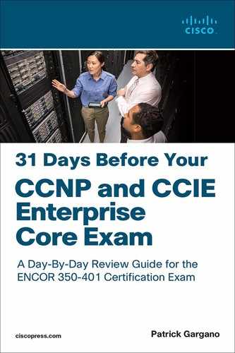
Having redundant equipment alone does not guarantee uptime. In Figure 22-1, both Router A and Router B are responsible for routing packets for the 10.1.10.0/24 subnet. Because the routers are deployed as a redundant pair, if Router A becomes unavailable, the Interior Gateway Protocol (IGP) can quickly and dynamically converge and determine that Router B should now transfer packets that would otherwise have gone through Router A. Most workstations, servers, and printers, however, do not receive this type of dynamic routing information.

Figure 22-1 Default Gateway Redundancy Example
Each end device is configured with a single default gateway Internet Protocol (IP) address that does not dynamically update when the network topology changes. If the default gateway fails, the local device is unable to send packets off the local network segment. As a result, the host is isolated from the rest of the network. Even if a redundant router exists that could serve as a default gateway for that segment, there is no dynamic method by which these devices can determine the address of a new default gateway.
First Hop Redundancy Protocol
Figure 22-2 represents a generic router FHRP with a set of routers working together to present the illusion of a single router to the hosts on the local-area network (LAN). By sharing an IP (Layer 3) address and a Media Access Control (MAC) (Layer 2) address, two or more routers can act as a single "virtual" router.

Figure 22-2 FHRP Operations
Hosts that are on the local subnet configure the IP address of the virtual router as their default gateway. When a host needs to communicate to another IP host on a different subnet, it uses Address Resolution Protocol (ARP) to resolve the MAC address of the default gateway. The ARP resolution returns the MAC address of the virtual router. The packets that devices send to the MAC address of the virtual router can then be routed to their destination by any active or standby router that is part of that virtual router group.
You use an FHRP to coordinate two or more routers as the devices that are responsible for processing the packets that are sent to the virtual router. The host devices send traffic to the address of the virtual router. The actual (physical) router that forwards this traffic is transparent to the end stations.
The redundancy protocol provides the mechanism for determining which router should take the active role in forwarding traffic and determining when a standby router should take over that role. The transition from one forwarding router to another is also transparent to the end devices.
Cisco routers and switches can support three different FHRP technologies:
• Hot Standby Router Protocol (HSRP): HSRP is an FHRP that Cisco designed to create a redundancy framework between network routers or multilayer switches to achieve default gateway failover capabilities. Only one router forwards traffic. HSRP is defined in RFC 2281.
• Virtual Router Redundancy Protocol (VRRP): VRRP is an open FHRP standard that offers the ability to add more than two routers for additional redundancy. Only one router forwards traffic. VRRP is defined in RFC 5798.
• Gateway Load Balancing Protocol (GLBP): GLBP is an FHRP that Cisco designed to allow multiple active forwarders to handle load balancing for outgoing traffic. (GLBP is beyond the scope of the ENCOR exam and is therefore not covered in this book.)
A common feature of FHRPs is to provide default gateway failover that is transparent to hosts.
Figure 22-3 illustrates what occurs when the active device or active forwarding link fails:
1. The standby router stops seeing hello messages from the forwarding router.
2. The standby router assumes the role of the forwarding router.
3. Because the new forwarding router assumes both the IP and MAC addresses of the virtual router, the end stations see no disruption in service.
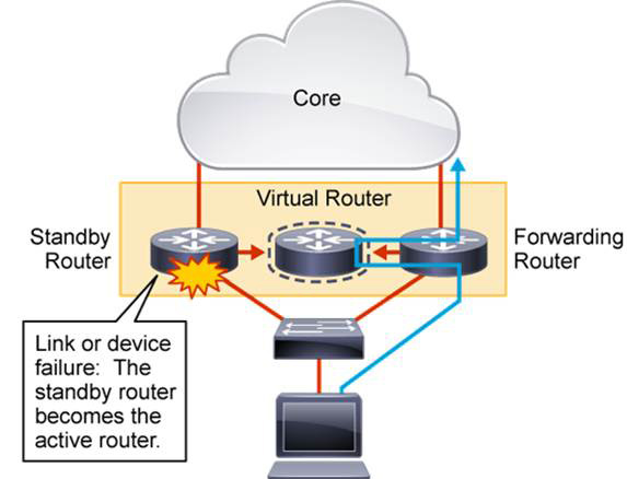
Figure 22-3 FHRP Failover Process
HSRP
HSRP is a Cisco-proprietary protocol that was developed to allow several multilayer switches or routers to appear as a single gateway IP address. HSRP allows two physical routers to work together in an HSRP group to provide a virtual IP address and an associated virtual MAC address.
The end hosts use the virtual IP address as their default gateway and learn the virtual MAC address via ARP. One of the routers in the group is active and responsible for the virtual addresses. The other router is in a standby state and monitors the active router.
If there is a failure on the active router, the standby router assumes the active state. The virtual addresses are always functional, regardless of which physical router is responsible for them. The end hosts are not aware of any changes in the physical routers.
HSRP defines a standby group of routers, as illustrated in Figure 22-4, with one router that is designated as the active router. HSRP provides gateway redundancy by sharing IP and MAC addresses between redundant gateways. The protocol consists of virtual MAC and IP addresses that two routers that belong to the same HSRP group share with each other.

Figure 22-4 HSRP Standby Group
The HSRP active route has the following characteristics:
• Responds to default gateway ARP requests with the virtual router MAC address
• Assumes active forwarding of packets for the virtual router
• Sends hello messages
• Knows the virtual router IP address
The HSRP standby route has the following characteristics:
• Sends hello messages
• Listens for periodic hello messages
• Knows the virtual IP address
• Assumes active forwarding of packets if it does not hear from the active router
Hosts on the IP subnet that are serviced by HSRP configure their default gateway with the HSRP group virtual IP address. The packets that are received on the virtual IP address are forwarded to the active router.
The function of the HSRP standby router is to monitor the operational status of the HSRP group and to quickly assume the packet-forwarding responsibility if the active router becomes inoperable.
HSRP Group
You assign routers to a common HSRP group by using the following interface configuration command:
Router(config-if)# standby group-number ip virtual-ip
If you configure HSRP on a multilayer switch, it is a good practice to configure the HSRP group number equal to the VLAN number. Doing so makes troubleshooting easier. HSRP group numbers are locally significant to an interface. For example, HSRP Group 1 on interface VLAN 22 is independent from HSRP Group 1 on interface VLAN 33.
One of the two routers in a group is elected as active and the other will be elected as standby. In an HSRP group with more routers, the other routers are in the listen state. Roles are elected based on the exchange of HSRP hello messages. When the active router fails, the other HSRP routers stop seeing hello messages from the active router. The standby router then assumes the role of the active router. If other routers participate in the group, then contend to be the new standby router. If both the active and standby routers fail, all other routers in the group contend for the active and standby router roles. As the new active router assumes both the IP address and the MAC address of the virtual router, the end stations see no disruption in the service. The end stations continue to send packets to the virtual router MAC address, and the new active router forwards the packets toward their destination.
HSRPv1 active and standby routers send hello messages to the multicast address 224.0.0.2, UDP port 1985.
The ICMP protocol allows a router to redirect an end station to send packets for a particular destination to another router on the same subnet—if the first router knows that the other router has a better path to that particular destination. As with default gateways, if the router to which an end station has been redirected for a particular destination fails, the end station packets to that destination are not delivered. In standard HSRP, this action is exactly what happens. For this reason, it is recommended to disable ICMP redirects if HSRP is turned on.
The HSRPv1 virtual MAC address is in the format 0000.0c07.acXX, where XX is the HSRP group number, converted from decimal to hexadecimal. Clients use this MAC address to forward data.
Figure 22-5 illustrates what occurs when PC1 tries to reach the server at address 192.168.2.44. In this scenario, the virtual IP address for Standby Group 1 is 192.168.1.1.

Figure 22-5 HSRP Forwarding
If an end station sends a packet to the virtual router MAC address, the active router receives and processes that packet. If an end station sends an ARP request with the virtual router IP address, the active router replies with the virtual router MAC address. In this example, R1 assumes the active role and forwards all frames that are addressed to the well-known MAC address 0000.0c07.ac01. Whereas ARP and ping use the HSRP virtual MAC address, the router responds to traceroute with its own MAC address. This is useful in troubleshooting when you need to determine which actual router is used for the traffic flow.
During a failover transition, the newly active router sends three gratuitous ARP requests so that the Layer 2 devices can learn the new port of the virtual MAC address.
HSRP Priority and HSRP Preempt
The HSRP priority is a parameter that enables you to choose the active router between HSRP-enabled devices in a group. The priority is a value between 0 and 255. The default value is 100. The device with the highest priority becomes active.
If HSRP group priorities are the same, the device with the highest IP address becomes active. In the example illustrated in Figure 22-5, R1 is the active router since it has the highest IP address.
Setting priority is wise for deterministic reasons. You want to know how your network will behave under normal conditions. Knowing that R1 is the active gateway for clients in the 192.168.1.0/24 LAN enables you to write good documentation.
Use the following interface configuration command to change the HSRP priority of an interface for a specific group:
Router(config-if)# standby group-number priority priority-value
Changing the priority of R2 to 110 for standby group 1 does not automatically allow it to become the active router because preemption is not enabled by default. Preemption is the ability of an HSRP-enabled device to trigger the reelection process. You can configure a router to preempt or immediately take over the active role if its priority is the highest at any time. Use the following interface configuration command to change the HSRP priority:
Router(config-if)# standby group preempt [delay [minimum seconds] [reload seconds]]
By default, after you enter this command, the local router can immediately preempt another router that has the active role. To delay the preemption, use the delay keyword followed by one or both of the following parameters:
• Add the minimum keyword to force the router to wait for a specified number of seconds (0 to 3600) before attempting to overthrow an active router with a lower priority. This delay time begins as soon as the router is capable of assuming the active role, such as after an interface comes up or after HSRP is configured.
• Add the reload keyword to force the router to wait for a specified number of seconds (0 to 3600) after it has been reloaded or restarted. This is useful if there are routing protocols that need time to converge. The local router should not become the active gateway before its routing table is fully populated; if it becomes the active gateway too soon, it might not be capable of routing traffic properly.
Preemption is an important feature of HSRP that allows the primary router to resume the active role when it comes back online after a failure or a maintenance event. Preemption is a desired behavior because it forces a predictable routing path for the LAN traffic during normal operations. It also ensures that the Layer 3 forwarding path for a LAN parallels the Layer 2 STP forwarding path whenever possible.
When a preempting device is rebooted, HSRP preemption communication should not begin until the router has established full connectivity with the rest of the network. This situation allows the routing protocol convergence to occur more quickly, after the preferred router is in an active state.
To accomplish this setup, measure the system boot time and set the HSRP preemption delay to a value that is about 50% greater than the boot time of the device. This value ensures that the router establishes full connectivity to the network before the HSRP communication occurs.
HSRP Timers
An HSRP hello message contains the priority of the router, the hello time, and the hold time parameter values. The hello timer parameter value indicates the interval of time between the hello messages that the router sends. The hold time parameter value indicates how long the current hello message is considered valid. The standby timers command includes an msec parameter to allow for subsecond failovers. Lowering the hello timer results in increased traffic for hello messages and should be used cautiously.
If an active router sends a hello message, the receiving routers consider the hello message to be valid for one hold time period. The hold time value should be at least three times the value of the hello time. The hold time value must be greater than the value of the hello time.
You can adjust the HSRP timers to tune the performance of HSRP on distribution devices in order to increase their resilience and reliability in routing packets off the local LAN.
By default, the HSRP hello time is 3 seconds, and the hold time is 10 seconds, which means the failover time could be as much as 10 seconds for clients to start communicating with the new default gateway. Sometimes, this interval may be excessive for application support. The hello time and the hold time parameters are configurable. To configure the time between the hello messages and the time before other group routers declare the active or standby router to be nonfunctioning, enter the following command in interface configuration mode:
Router(config-if)# standby group-number timers [msec] hellotime [msec] holdtime
The hello interval is specified in seconds (1 to 255) unless the msec keyword is used. The dead interval, also specified in seconds (1 to 255), is a time before the active or standby router is declared to be down, unless the msec keyword is used.
The hello and dead timer intervals must be identical for all the devices within an HSRP group.
To reinstate the default standby timer values, enter the no standby group-number timers command.
Ideally, to achieve fast convergence, the timer values should be configured to be as low as possible. Within milliseconds after the active router fails, the standby router can detect the failure, expire the hold time interval, and assume the active role.
Nevertheless, the timer configuration should also consider other parameters that are relevant to the network convergence. For example, both HSRP routers may run dynamic routing protocols. The routing protocol probably has no awareness of the HSRP configuration, and it sees both routers as individual hops toward other subnets. If HSRP failover occurs before the dynamic routing protocol converges, suboptimal routing information may still exist. In a worst-case scenario, the dynamic routing protocol continues seeing the failed router as the best next hop to other networks, and packets are lost. When you configure HSRP timers, make sure they harmoniously match the other timers that can influence which path is chosen to carry packets in your network.
HSRP State Transition
An HSRP router can be in one of five states, as illustrated in Table 22-1.
Table 22-1 HSRP States
When a router exists in one of these states, it performs the actions that are required by that state. Not all HSRP routers in the group transition through all states. In an HSRP group with three or more routers, a router that is not the standby or active router remains in the listen state. In other words, no matter how many devices are participating in HSRP, only one device can be in the active state, and one other device can be in the standby state. All other devices are in the listen state.
All routers begin in the initial state. This state is the starting state, and it indicates that HSRP is not running. This state is entered via a configuration change, such as when HSRP is disabled on an interface or when an HSRP-enabled interface is first brought up (such as when the no shutdown command is issued).
The purpose of the listen state is to determine if there are any active or standby routers already present in the group. In the speak state, the routers actively participate in the election of the active router, standby router, or both.
HSRP Advanced Features
There are a few options available with HSRP that can allow for more complete insight into network capabilities and add security to the redundancy process. Objects can be tracked, allowing for events other than actual device or HSRP interface failures to trigger state transition. By using Multigroup Hot Standby Routing Protocol (MHSRP), two routers can actively process flows for different standby groups. You can also add security to HSRP by configuring authentication on the protocol.
HSRP Object Tracking
HSRP can track objects, and it can decrement priority if an object fails. By default, the HSRP active router loses its status only if the HSRP-enabled interface fails or the HSRP router itself fails. However, it is possible to use object tracking to trigger an HSRP active router election.
When the conditions defined by the object are fulfilled, the router priority remains the same. When the object fails, the router priority is decremented. The amount of decrease can be configured. The default value is 10.
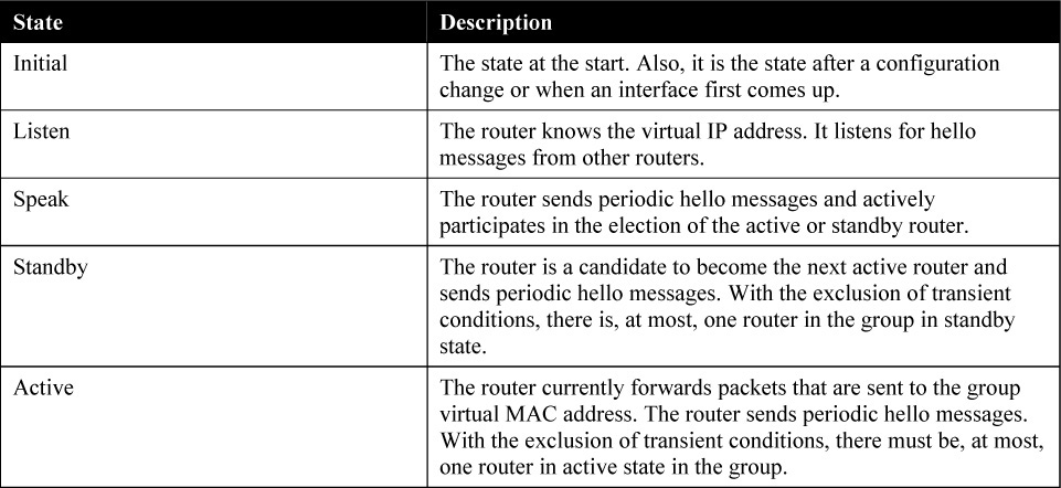
In Figure 22-6, R1 and R2 are configured with HSRP. R2 is configured to be the active default gateway, and R1 will take over if R2 or the HSRP-enabled interface on R2 fails.

Figure 22-6 HSRP with No Interface Tracking
What happens if the R2 uplink fails? The uplink interface is not an HSRP-enabled interface, so its failure does not affect HSRP. R2 is still the active default gateway. All the traffic from PC1 to the server now has to go to R2, and then it gets routed back to R1 and forwarded to the server; this is in an inefficient traffic path.
HSRP provides a solution to this problem: HSRP object tracking. Object tracking allows you to specify another interface on the router for the HSRP process to monitor to alter the HSRP priority for a given group. If the line protocol for the specified interface goes down, the HSRP priority of this router is reduced, allowing another HSRP router with a higher priority to become active. Preemption must be enabled on both routers for this feature to work correctly.
Consider the same scenario as before. In Figure 22-7, the R2 uplink interface fails, but this time HSRP, by virtue of HSRP object tracking, detects this failure, and the HSRP priority for R2 is decreased by 20. With preemption enabled, R1 then takes over as the active HSRP peer because it has a higher priority.
Figure 22-7 HSRP with Interface Object Tracking
Configuring interface object tracking for HSRP is a two-step process:
1. Define the tracking object criteria by using the global configuration command track object-number interface interface-id line-protocol.
2. Associate the object with a specific HSRP group by using the standby group-number track object-id decrement decrement-value.
Example 22-1 shows the commands used on R1 and R2 in Figure 22-7 to configure interface object tracking for HSRP Standby Group 1. Interface GigabitEthernet 0/0 is the HSRP-enabled interface, and interface GigabitEthernet 0/1 is the tracked interface. Preemption is enabled on the HSRP-enabled interface on R1, which allows it to become the new active router when R2’s GigabitEthernet 0/1 interface fails. If and when the GigabitEthernet 0/1 interface is repaired, R2 can reclaim the active status, thanks to the preemption feature because its priority returns to 110
Example 22-1 Configuring Object Tracking for HSRP
R2(config)# track 10 interface GigabitEthernet 0/1 line-protocol
R2(config)# interface GigabitEthernet 0/0
R2(config-if)# standby 1 priority 110
R2(config-if)# standby 1 track 10 decrement 20
R2(config-if)# standby 1 preempt
R1(config)# interface GigabitEthernet 0/0
R1(config-if)# standby 1 preempt
You can apply multiple tracking statements to an interface. This may be useful, for example, if the currently active HSRP interface will relinquish its status only upon the failure of two (or more) tracked interfaces.
Beside interfaces, it is possible to also track the presence of routes in the routing table, as well as the status of an IP SLA. A tracked IP route object is considered up and reachable when a routing table entry exists for the route and the route is accessible. To provide a common interface to tracking clients, route metric values are normalized to the range of 0 to 255, where 0 is connected, and 255 is inaccessible. You can track route reachability or even metric values to determine best-path values to the target network. The tracking process uses a per-protocol configurable resolution value to convert the real metric to the scaled metric. The metric value that is communicated to clients is always such that a lower metric value is better than a higher metric value. Use the track object-number ip route route/prefix-length reachability command to track a route in the routing table.
For an IP SLA, besides tracking the operational state, it is possible to track advanced parameters such as IP reachability, delay, or jitter. Use the track object-number ip sla operation-number [state | reachability] command to track an IP SLA.
Use the show track object-number command to verify the state of the tracked interface and use the show standby command to verify that tracking is configured.
HSRP Multigroup
HSRP does not support load sharing as part of the protocol specification. However, load sharing can be achieved through the configuration of MHSRP.
In Figure 22-8, two HSRP-enabled multilayer switches participate in two separate VLANs, using IEEE 802.1Q trunks. If you leave the default HSRP priority values, a single multilayer switch will likely become an active gateway for both VLANs, effectively utilizing only one uplink toward the core of the network.
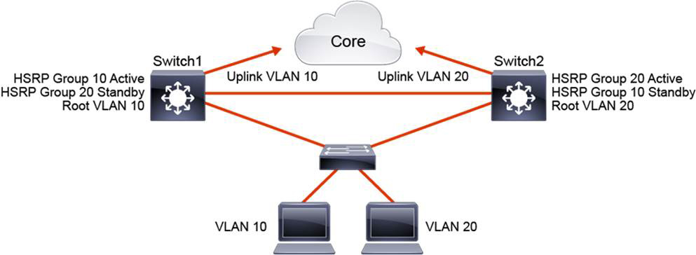
Figure 22-8 HSRP Load Balancing with MHSRP
To use both paths toward the core network, you can configure HSRP with MHSRP. Group 10 is configured for VLAN 10. Group 20 is configured for VLAN 20. For group 10, Switch1 is configured with a higher priority to become the active gateway, and Switch2 becomes the standby gateway. For group 20, Switch2 is configured with a higher priority to become the active gateway, and Switch1 becomes the standby router. Now both uplinks toward the core are utilized: one with VLAN 10 and one with VLAN 20 traffic.
Example 22-2 shows the commands to configure MHSRP on Switch1 and Switch2 in Figure 22-8. Switch1 has two HSRP groups that are configured for two VLANs and that correspond to the STP root configuration. Switch1 is the active router for HSRP group 10 and is the standby router for group 20. Switch2’s configuration mirrors the configuration on Switch1.
Example 22-2 Configuring MHSRP
Switch1(config)# spanning-tree vlan 10 root primary
Switch1(config)# spanning-tree vlan 20 root secondary
Switch1(config)# interface vlan 10
Switch1(config-if)# ip address 10.1.10.2 255.255.255.0
Switch1(config-if)# standby 10 ip 10.1.10.1
Switch1(config-if)# standby 10 priority 110
Switch1(config-if)# standby 10 preempt
Switch1(config-if)# exit
Switch1(config)# interface vlan 20
Switch1(config-if)# ip address 10.1.20.2 255.255.255.0
Switch1(config-if)# standby 20 ip 10.1.20.1
Switch1(config-if)# standby 20 priority 90
Switch1(config-if)# standby 20 preempt
Switch2(config)# spanning-tree vlan 10 root secondary
Switch2(config)# spanning-tree vlan 20 root primary
Switch2(config)# interface vlan 10
Switch2(config-if)# ip address 10.1.10.3 255.255.255.0
Switch2(config-if)# standby 10 ip 10.1.10.1
Switch2(config-if)# standby 10 priority 90
Switch2(config-if)# standby 10 preempt
Switch2(config-if)# exit

Switch2(config)# interface vlan 20
Switch2(config-if)# ip address 10.1.20.3 255.255.255.0
Switch2(config-if)# standby 20 ip 10.1.20.1
Switch2(config-if)# standby 20 priority 110
Switch2(config-if)# standby 20 preempt
HSRP Authentication
HSRP authentication prevents rogue Layer 3 devices on the network from joining the HSRP group.
A rogue device may claim the active role and can prevent the hosts from communicating with the rest of the network, creating a DoS attack. A rogue router could also forward all traffic and capture traffic from the hosts, achieving a man-in-the-middle attack.
HSRP provides two types of authentication: plaintext and MD5.
To configure plaintext authentication, use the following interface configuration command on HSRP peers:
Router(config-if)# standby group-number authentication string
With plaintext authentication, a message that matches the key that is configured on an HSRP peer is accepted. The maximum length of a key string is eight characters. Plaintext messages can easily be intercepted, so avoid plaintext authentication if MD5 authentication is available.
To configure MD5 authentication, use the following interface configuration command on HSRP peers:
Router(config-if)# standby group-number authentication md5 [key-chain key-chain | key-string key-string]
Using MD5, a hash is computed on a portion of each HSRP message. The hash is sent along with the HSRP message. When a peer receives the message and a hash, it performs hashing on the received message. If the received hash and the newly computed hash match, the message is accepted. It is very difficult to reverse the hash value itself, and hash keys are never exchanged. MD5 authentication is preferred.
Instead of using a single MD5 key, you can define MD5 strings as keys on a keychain. This method is flexible because it means you can define multiple keys with different validity times.
HSRP Versions
There are two HSRP versions available on most Cisco routers and multilayer switches: HSRPv1 and HSRPv2. Table 22-2 compares the two versions.
Table 22-2 HSRP Versions
To enable HSRPv2 on all devices, use the following command in interface configuration mode:
Router(config-if)# standby version 2
HSRPv1 is the default version on Cisco IOS devices. HSRPv2 is supported in Cisco IOS Software Release 12.2(46)SE and later. HSRPv2 allows group numbers up to 4095, thus allowing you to use the VLAN number as the group number.
HSRPv2 must be enabled on an interface before HSRP for IPv6 can be configured.
HSRPv2 does not interoperate with HSRPv1. All devices in an HSRP group must have the same version configured; otherwise, the hello messages are not understood. An interface cannot operate both HSRPv1 and HSRPv2 because they are mutually exclusive.
The MAC address of the virtual router and the multicast address for the hello messages are different with HSRPv2. HSRPv2 uses the new IP multicast address 224.0.0.102 to send the hello packets, whereas HSRPv1 uses the multicast address 224.0.0.2. This new address allows Cisco Group Management Protocol (CGMP) multicast processing to be enabled at the same time as HSRP.
HSRPv2 has a different packet format from HSRPv1. It includes a 6-byte identifier field that is used to uniquely identify the sender of the message by its interface MAC address, which makes troubleshooting easier.
HSRP Configuration Example
Figure 22-9 shows a topology in which R1 and R2 are gateway devices available for PCs in the 192.168.1.0/24 subnet. R1 is configured to become the HSRP active router, and R2 is the HSRP standby router. R1 is configured for object tracking so that it can track the status of its GigabitEthernet 0/0 interface. If the interface fails, R2 should become the HSRP active router.
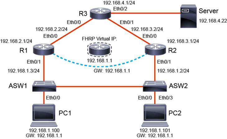
Figure 22-9 HSRP Configuration Example
Example 22-3 shows a complete HSRP configuration, including the use of HSRPv2, object tracking, authentication, timer adjustment, and preemption delay.
Example 22-3 Configuring HSRP
R1(config)# track 5 interface GigabitEthernet0/0 line-protocol
R1(config)# interface GigabitEthernet 0/1
R1(config-if)# standby version 2
R1(config-if)# standby 1 ip 192.168.1.1
R1(config-if)# standby 1 priority 110
R1(config-if)# standby 1 authentication md5 key-string 31DAYS
R1(config-if)# standby 1 timers msec 200 msec 750
R1(config-if)# standby 1 preempt delay minimum 300
R1(config-if)# standby 1 track 5 decrement 20
R2(config)# interface GigabitEthernet 0/1
R2(config-if)# standby version 2
R2(config-if)# standby 1 ip 192.168.1.1
R2(config-if)# standby 1 authentication md5 key-string 31DAYS
R2(config-if)# standby 1 timers msec 200 msec 750
R2(config-if)# standby 1 preempt
R2 is not configured with object tracking because it will become active only if R1 reports a lower priority. Also, notice the preemption delay configured on R1. This gives R1 time to fully converge with the network before reclaiming the active status when GigabitEthernet 0/0 is repaired. No preemption delay is configured on R2 because it needs to immediately claim the active status once R1’s priority drops below 100.
Example 22-4 shows the use of the HSGHSverification commands show track, show standby brief, and show standby.
Example 22-4 Verifying Object Tracking and HSRP
R1# show track
Track 5
  Interface GigabitEthernet0/0 line-protocol
  Line protocol is Up
    1 change, last change 00:01:08


R1# show standby
GigabitEthernet0/1 - Group 1 (version 2)
  State is Active
    2 state changes, last state change 00:03:16
  Virtual IP address is 192.168.1.1
  Active virtual MAC address is 0000.0c9f.f001
    Local virtual MAC address is 0000.0c9f.f001 (v2 default)
  Hello time 200 msec, hold time 750 msec
    Next hello sent in 0.064 secs
  Authentication MD5, key-string
  Preemption enabled, delay min 300 secs
  Active router is local
  Standby router is 192.168.1.2, priority 100 (expires in 0.848 sec)
  Priority 110 (configured 110)
    Track object 5 state Up decrement 20
  Group name is "hsrp-Et0/1-1" (default)

R1# show standby brief
                     P indicates configured to preempt.
                     |
Interface   Grp  Pri P State   Active          Standby         Virtual IP
Gi0/1       1    110 P Active  local           192.168.1.2     192.168.1.1
The show track command output confirms that GigabitEthernet 0/0 is currently operational. The show standby command confirms that HSRPv2 is enabled, that its current state is active, while R2 is standby. The output also confirms that MD5 authentication and preemption are enabled. Finally, notice that the tracking object is currently up but that it decrements the priority by a value of 20 if the tracking object fails.
The show standby brief command provides a snapshot of the HSRP status on R1’s GigabitEthernet 0/1 interface.
VRRP
VRRP is similar to HSRP, both in operation and in configuration. The VRRP master is analogous to the HSRP active gateway, and the VRRP backup is analogous to the HSRP standby gateway. A VRRP group has one master device and one or multiple backup devices. A device with the highest priority is the elected master. The priority can be a number between 0 and 255. The priority value 0 has a special meaning: It indicates that the current master has stopped participating in VRRP. This setting is used to trigger backup devices to quickly transition to master without having to wait for the current master to time out.
VRRP differs from HSRP in that it allows you to use an address of one of the physical VRRP group members as a virtual IP address. In this case, the device with the used physical address is a VRRP master whenever it is available.
The master is the only device that sends advertisements (analogous to HSRP hellos). Advertisements are sent to the 224.0.0.18 multicast address, with protocol number 112. The default advertisement interval is 1 second. The default hold time is 3 seconds. HSRP, in comparison, has the default hello timer set to 3 seconds and the hold timer set to 10 seconds. VRRP uses the MAC address format 0000.5e00.01XX, where XX is the group number, in hexadecimal.
Cisco devices allow you to configure VRRP with millisecond timers. You need to manually configure the millisecond timer values on both the master and backup devices. Use the millisecond timers only when absolutely necessary and with careful consideration and testing. Millisecond values work only under favorable circumstances, and you must be aware that the use of the millisecond timer values restricts VRRP operation to Cisco devices only.
In Figure 22-10, Router A, Router B, and Router C are configured as VRRP virtual routers and are members of the same VRRP group. Because Router A has the highest priority, it is elected the master for this VRRP group. End-user devices use it as their default gateway. Routers B and C function as virtual router backups. If the master fails, the device with the highest configured priority becomes the master and provides uninterrupted service for the LAN hosts. When Router A recovers and with preemption enabled, Router A becomes the master again. Unlike with HSRP, with VRRP, preemption is enabled by default.
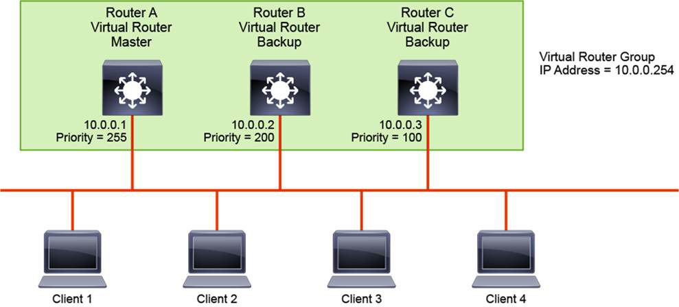
Figure 22-10 VRRP Example
Load sharing is also available with VRRP and, as with HSRP, multiple virtual router groups can be configured. For instance, in Figure 22-10, you could configure Clients 3 and 4 to use a different default gateway than Clients 1 and 2 use. Then you would configure the three multilayer switches with another VRRP group and designate Router B to be the master VRRP device for the second group.
RFC 5798 defines VRRP support for both IPv4 and IPv6. The default VRRP version on Cisco devices is VRRPv2, and it only supports IPv4. To support both IPv4 and IPv6, you need to enable VRRPv3 by using the global configuration command fhrp version vrrp v3. Also, the configuration framework for VRRPv2 and VRRPv3 differ significantly. Legacy VRRPv2 is non-hierarchical in its configuration, while VRRPv3 uses the address family framework. To enter the VRRP address family configuration framework, enter the vrrp group-number address-family [ipv4 | ipv6] interface command.
Like HSRP, VRRP supports object tracking for interface state, IP route reachability, IP SLA state, IP SLA reachability, and so on.
VRRP Authentication
According to RFC 5798, operational experience and further analysis determined that VRRP authentication did not provide sufficient security to overcome the vulnerability of misconfigured secrets, and multiple masters could be elected. Due to the nature of VRRP, even cryptographically protecting VRRP messages does not prevent hostile nodes from behaving as if they are the VRRP master and creating multiple masters. Authentication of VRRP messages could prevent a hostile node from causing all properly functioning routers from going into the backup state. However, having multiple masters can cause as much disruption as having no routers, and authentication cannot prevent this. Also, even if a hostile node cannot disrupt VRRP, it can disrupt ARP and create the same effect as having all routers go into the backup state.
Independent of any authentication type, VRRP includes a mechanism (setting Time to Live [TTL] = 255, checking on receipt) that protects against VRRP packets being injected from another remote network. The TTL setting limits most vulnerability to local attacks.
With Cisco IOS devices, the default VRRPv2 authentication is plaintext. MD5 authentication can be configured by specifying a key string or, as with HSRP, reference to a keychain. Use the vrrp group-number authentication text key-string command for plaintext authentication, and use the vrrp group-number authentication md5 [key-chain key-chain | key-string key-string] command for MD5 authentication.
VRRP Configuration Example
Using the topology in Figure 22-9, Example 22-5 shows the configuration of legacy VRRPv2, and Example 22-6 shows the configuration for address family VRRPv3. R1 is configured as the VRRP master, and R2 is configured as the VRRP backup. Both examples also demonstrate the use of the priority and track features.
Example 22-5 Configuring Legacy VRRPv2
R1(config)# track 5 interface GigabitEthernet0/0 line-protocol
R1(config)# interface GigabitEthernet 0/1
R1(config-if)# vrrp 1 ip 192.168.1.1
R1(config-if)# vrrp 1 priority 110
R1(config-if)# vrrp 1 authentication md5 key-string 31DAYS
R1(config-if)# vrrp 1 preempt delay minimum 300
R1(config-if)# vrrp 1 track 5 decrement 20
R2(config)# interface GigabitEthernet 0/1
R2(config-if)# vrrp 1 ip 192.168.1.1
R2(config-if)# vrrp 1 authentication md5 key-string 31DAYS
In Example 22-5, notice that the legacy VRRP syntax is practically identical to the HSRP syntax. Recall that preemption is enabled by default in VRRP.
Example 22-6 Configuring Address Family VRRPv3
R1(config)# track 5 interface GigabitEthernet0/0 line-protocol
R1(config)# fhrp version vrrp 3
R1(config)# interface GigabitEthernet 0/1
R1(config-if)# vrrp 1 address-family ipv4
R1(config-if-vrrp)# address 192.168.1.1
R1(config-if-vrrp)# priority 110
R1(config-if-vrrp)# preempt delay minimum 300
R1(config-if-vrrp)# track 5 decrement 20
R2(config)# fhrp version vrrp 3
R2(config)# interface GigabitEthernet 0/1
R2(config-if)# vrrp 1 address-family ipv4
R2(config-if-vrrp)# address 192.168.1.1
In Example 22-6, in the VRRP address family configuration framework, the commands are similar to those used in Example 22-5 except that they are entered hierarchically under the appropriate address families. All VRRP parameters and options are entered under the VRRP instance. Notice that authentication is not supported. Also, it is possible to use VRRPv2 with the address family framework. Use the vrrpv2 command under the VRRP instance to achieve this.
To verify the operational state of VRRP, use the show vrrp brief and show vrrp commands, as illustrated in Example 22-7. The output format is similar to what you saw earlier with HSRP. The first part of the example displays the output when using legacy VRRPv2. The second part displays the output when using address family VRRPv3.
Example 22-7 Verifying Legacy VRRPv2 and Address Family VRRPv3
! Legacy VRRPv2
R1# show vrrp brief
Interface          Grp Pri Time  Own Pre State   Master addr     Group addr
Gi0/1              1   110 3570       Y  Master  192.168.1.3     192.168.1.1
!
R1# show vrrp
Ethernet0/1 - Group 1
  State is Master
  Virtual IP address is 192.168.1.1
  Virtual MAC address is 0000.5e00.0101
  Advertisement interval is 1.000 sec
  Preemption enabled, delay min 300 secs
  Priority is 110
    Track object 5 state UP decrement 20
  Master Router is 192.168.1.3 (local), priority is 110
  Master Advertisement interval is 1.000 sec
  Master Down interval is 3.609 sec (expires in 3.049 sec)
! Address Family VRRPv3
R1# show vrrp brief
  Interface          Grp  A-F Pri  Time Own Pre State   Master addr/Group addr
  Gi0/1                1 IPv4 110     0  N   Y  MASTER  192.168.1.3 (local) 192.168.1.1
!
R1# show vrrp

GigabitEthernet0/1 - Group 1 - Address-Family IPv4
  State is MASTER
  State duration 2 mins 14.741 secs
  Virtual IP address is 192.168.1.1
  Virtual MAC address is 0000.5E00.0114
  Advertisement interval is 1000 msec
  Preemption enabled, delay min 300 secs (0 msec remaining)
  Priority is 110
    Track object 5 state UP decrement 20
  Master Router is 192.168.1.3 (local), priority is 110
  Master Advertisement interval is 1000 msec (expires in 292 msec)
  Master Down interval is unknown
Study Resources
For today’s exam topics, refer to the following resources for more study.
