Day 29. LAN Connectivity
ENCOR 350-401 Exam Topics
• Layer 2
• Troubleshoot static and dynamic 802.1q trunking protocols
Key Topics
Today we review concepts related to configuring, verifying, and troubleshooting VLANs, 802.1Q trunking, Dynamic Trunking Protocol (DTP), VLAN Trunking Protocol (VTP), and inter-VLAN routing using a router and a Layer 3 switch.
VLAN Overview
A VLAN is a logical broadcast domain that can span multiple physical LAN segments. Within a switched internetwork, VLANs provide segmentation and organizational flexibility. You can design a VLAN structure that lets you group stations that are segmented logically by functions, project teams, and applications without regard to the physical location of the users. Ports in the same VLAN share broadcasts. Ports in different VLANs do not share broadcasts. Containing broadcasts within a VLAN improves the overall performance of the network.
Each VLAN that you configure on a switch implements address learning, forwarding, and filtering decisions and loop-avoidance mechanisms, just as though the VLAN were a separate physical bridge. A Cisco Catalyst switch implements VLANs by restricting traffic forwarding to destination ports that are in the same VLAN as the originating ports. When a frame arrives on a switch port, the switch must retransmit the frame only to the ports that belong to the same VLAN. A VLAN that is operating on a switch limits transmission of unicast, multicast, and broadcast traffic, as shown in Figure 29-1, where traffic is forwarded between devices within the same VLAN, in this case VLAN 2, while traffic is not forwarded between devices in different VLANs

Figure 29-1 VLAN Traffic Patterns
A VLAN can exist on a single switch or span multiple switches. VLANs can include stations in single- or multiple-building infrastructures. The process of forwarding network traffic from one VLAN to another VLAN using a router or Layer 3 switch is called inter-VLAN routing. In a campus design, a network administrator can design a campus network with one of two models: end-to-end VLANs or local VLANs.
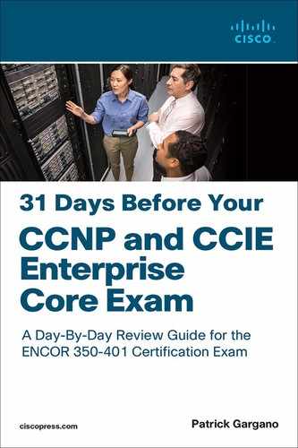
The term end-to-end VLAN refers to a single VLAN that is associated with switch ports widely dispersed throughout an enterprise network on multiple switches. A Layer 2 switched campus network carries traffic for this VLAN throughout the network, as shown in Figure 29-2, where VLANs 1, 2, and 3 are spread across all three switches.
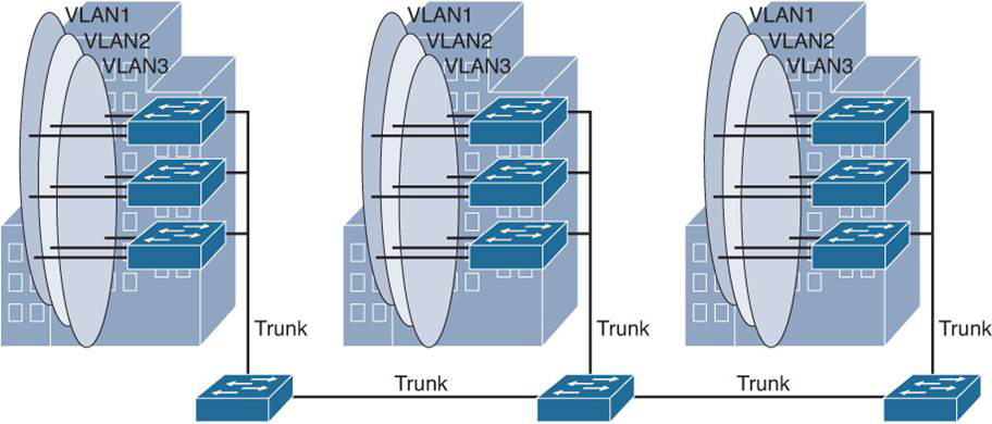
Figure 29-2 End-to-End VLANs
The typical campus enterprise architecture is usually based on the local VLAN model instead. In a local VLAN model, all users of a set of geographically common switches are grouped into a single VLAN, regardless of the organizational function of those users. Local VLANs are generally confined to a wiring closet, as shown in Figure 29-3. In the local VLAN model, Layer 2 switching is implemented at the access level, and routing is implemented at the distribution and core levels, as discussed on Day 31, “Enterprise Network Architecture,” to enable users to maintain access to the resources they need. An alternative design is to extend routing to the access layer, with routed links between the access switches and distribution switches. In Figure 29-3, notice the use of trunk links between switches and buildings. These are special links that can carry traffic for all VLANs. Trunking is explained in greater detail later today.
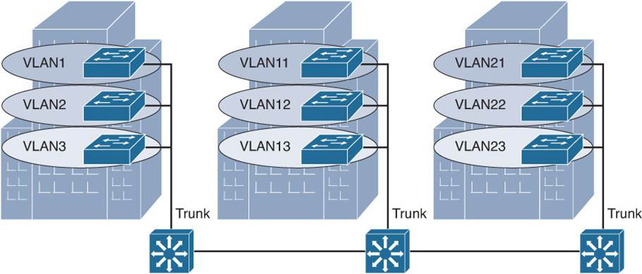
Figure 29-3 Local VLANs
Creating a VLAN
To create a VLAN, use the vlan global configuration command and enter the VLAN configuration mode. Use the no form of this command to delete the VLAN. Example 29-1 shows how to add VLAN 2 to the VLAN database and how to name it Sales. VLAN 20 is also created, and it is named IT.
Example 29-1 Creating a VLAN
Switch# configure terminal
Switch(config)# vlan 2
Switch(config-vlan)# name Sales
Switch(config-vlan)# vlan 20
Switch(config-vlan)# name IT
To add a VLAN to the VLAN database, assign a number and name to the VLAN. VLAN 1 is the factory default VLAN. Normal-range VLANs are identified with a number between 1 and 1001. The VLAN numbers 1002 through 1005 are reserved. VIDs 1 and 1002 to 1005 are automatically created, and you cannot remove them. The extended VLAN range is from 1006 to 4094. The configurations for VLANs 1 to 1005 are written to the vlan.dat file (VLAN database). You can display the VLANs by entering the show vlan command in privileged EXEC mode. The vlan.dat file is stored in flash memory.
Access Ports
When you connect an end system to a switch port, you should associate it with a VLAN in accordance with the network design. This procedure allows frames from that end system to be forwarded to other interfaces that also function on that VLAN. To associate a device with a VLAN, assign the switch port to which the device connects to a single-data VLAN. The switch port, therefore, becomes an access port. By default, all ports are members of VLAN 1. In Example 29-2, the GigabitEthernet 1/0/5 interface is assigned to VLAN 2, and the GigabitEthernet 1/0/15 interface is assigned to VLAN 20.
Example 29-2 Assigning a Port to a VLAN
Switch# configure terminal
Switch(config)# interface GigabitEthernet 1/0/5
Switch(config-if)# switchport mode access
Switch(config-if)# switchport access vlan 2
Switch(config-if)# interface GigabitEthernet 1/0/15
Switch(config-if)# switchport mode access
Switch(config-if)# switchport access vlan 20
After creating a VLAN, you can manually assign a port or many ports to this VLAN. An access port can belong to only one VLAN at a time.
Use the show vlan or show vlan brief command to display information about all configured VLANs, or use either the show vlan id vlan_number or show vlan name vlan-name command to display information about specific VLANs in the VLAN database, as shown in Example 29-3.
Example 29-3 Using show vlan Commands
Switch# show vlan

VLAN Name                             Status    Ports
---- -------------------------------- --------- -------------------------------
1    default                          active    Gi1/0/1, Gi1/0/2, Gi1/0/3
                                                Gi1/0/4, Gi1/0/6, Gi1/0/7
                                                Gi1/0/8, Gi1/0/9, Gi1/0/10
                                                Gi1/0/11, Gi1/0/12, Gi1/0/13
                                                Gi1/0/14, Gi1/0/16, Gi1/0/17
                                                Gi1/0/18, Gi1/0/19, Gi1/0/20
                                              Gi1/0/21, Gi1/0/22, Gi1/0/23
                                              Gi1/0/24
2    Sales                            active    Gi1/0/5
20   IT                               active    Gi1/0/15
1002 fddi-default                     act/unsup
1003 token-ring-default               act/unsup
1004 fddinet-default                  act/unsup
1005 trnet-default                    act/unsup

VLAN Type  SAID       MTU   Parent RingNo BridgeNo Stp  BrdgMode Trans1 Trans2
---- ----- ---------- ----- ------ ------ -------- ---- -------- ------ ------
1    enet  100001     1500  -      -      -        -    -        0      0
2    enet  100002     1500  -      -      -        -    -        0      0
20   enet  100020     1500  -      -      -        -    -        0      0
1002 fddi  101002     1500  -      -      -        -    -        0      0
1003 tr    101003     1500  -      -      -        -    -        0      0
1004 fdnet 101004     1500  -      -      -        ieee -        0      0
1005 trnet 101005     1500  -      -      -        ibm  -        0      0

Primary Secondary Type              Ports
------- --------- ----------------- ------------------------------------------
Switch# show vlan brief

VLAN Name                             Status    Ports
---- -------------------------------- --------- -------------------------------
1    default                          active    Gi1/0/1, Gi1/0/2, Gi1/0/3
                                                Gi1/0/4, Gi1/0/6, Gi1/0/7
                                                Gi1/0/8, Gi1/0/9, Gi1/0/10
                                                Gi1/0/11, Gi1/0/12, Gi1/0/13
                                                Gi1/0/14, Gi1/0/16, Gi1/0/17
                                                Gi1/0/18, Gi1/0/19, Gi1/0/20
                                              Gi1/0/21, Gi1/0/22, Gi1/0/23
                                              Gi1/0/24
2    Sales                            active    Gi1/0/5
20   IT                               active    Gi1/0/15
1002 fddi-default                     act/unsup
1003 token-ring-default               act/unsup
1004 fddinet-default                  act/unsup
1005 trnet-default                    act/unsup
Switch# show vlan id 2

VLAN Name                 Status    Ports
---- -------------------- -------   ---------------------
2    Sales                active    Gi1/0/5

VLAN Type SAID    MTU   Parent RingNo BridgeNo Stp  BrdgMode Trans1 Trans2
---- ---- ------- ----- ------ ------ -------- --- --------- ------ ------
2    enet 100002  1500  -      -      -        -    -        0      0

<... output omitted ...>
Switch# show vlan name IT

VLAN Name                 Status    Ports
---- -------------------- -------   ---------------------
20   IT                   active    Gi1/0/15

VLAN Type SAID    MTU   Parent RingNo BridgeNo Stp  BrdgMode Trans1 Trans2
---- ---- ------- ----- ------ ------ -------- --- --------- ------ ------
2    enet 100002  1500  -      -      -        -    -        0      0

<... output omitted ...>
Use the show interfaces switchport command to display switch port status and characteristics. The output in Example 29-4 shows information about the GigabitEthernet 1/0/5 interface, where VLAN 2 (Sales) is assigned and the interface is configured as an access port.
Example 29-4 Using the show interfaces switchport Command
Switch# show interfaces GigabitEthernet 1/0/5 switchport
Name: Gi1/0/5
Switchport: Enabled
Administrative Mode: static access
Operational Mode: static access
Administrative Trunking Encapsulation: dot1q
Negotiation of Trunking: On
Access Mode VLAN: 2 (Sales)
Trunking Native Mode VLAN: 1 (default)
Administrative Native VLAN tagging: enabled
Voice VLAN: none
Administrative private-vlan host-association: none
Administrative private-vlan mapping: none
Administrative private-vlan trunk native VLAN: none
Administrative private-vlan trunk Native VLAN tagging: enabled
Administrative private-vlan trunk encapsulation: dot1q
Administrative private-vlan trunk normal VLANs: none
Administrative private-vlan trunk associations: none
Administrative private-vlan trunk mappings: none
Operational private-vlan: none
Trunking VLANs Enabled: ALL
Pruning VLANs Enabled: 2-1001
Capture Mode Disabled
Capture VLANs Allowed: ALL

Protected: false
Unknown unicast blocked: disabled
Unknown multicast blocked: disabled
Appliance trust: none
802.1Q Trunk Ports
A port normally carries only the traffic for a single VLAN. For a VLAN to span multiple switches, a trunk is required to connect the switches. A trunk can carry traffic for multiple VLANs.
A trunk is a point-to-point link between one or more Ethernet switch interfaces and another networking device, such as a router or a switch. An Ethernet trunk carries the traffic of multiple VLANs over a single link and allows you to extend the VLANs across an entire network. A trunk does not belong to a specific VLAN; rather, it is a conduit for VLANs between switches and routers.
A special protocol is used to carry multiple VLANs over a single link between two devices. There are two trunking technologies: ISL and IEEE 802.1Q. ISL is a Cisco-proprietary implementation that is no longer widely used. The 802.1Q technology is the IEEE standard VLAN trunking protocol. This protocol inserts a 4-byte tag into the original Ethernet header and then recalculates and updates the FCS in the original frame and transmits the frame over the trunk link. A trunk could also be used between a network device and server or another device that is equipped with an appropriate 802.1Q-capable NIC.
Ethernet trunk interfaces support various trunking modes. You can configure an interface as trunking or nontrunking, and you can have an interface negotiate trunking with the neighboring interface.
By default, all configured VLANs are carried over a trunk interface on a Cisco Catalyst switch. On an 802.1Q trunk port, there is one native VLAN, which is untagged (by default, VLAN 1). Each of the other VLANs is tagged with a VID.
When Ethernet frames are placed on a trunk, they need additional information about the VLANs they belong to. This task is accomplished by using the 802.1Q encapsulation header. It is the responsibility of the Ethernet switch to look at the 4-byte tag field and determine where to deliver the frame. Figure 29-4 illustrates the tagging process that occurs on the Ethernet frame as it is placed on the 802.1Q trunk.
Figure 29-4 802.1Q Tagging Process
According to the IEEE 802.1Q-2018 revision of the 802.1Q standard, the tag has these four components:
• Tag Protocol Identifier (TPID; 16 bits): Uses EtherType 0x8100 to indicate that this frame is an 802.1Q frame.
• Priority Code Point (PCP; 3 bits): Carries the class of service (CoS) priority information for Layer 2 quality of service (QoS). Different PCP values can be used to prioritize different classes of traffic.
• Drop Eligible Indicator (DEI; 1 bit): Formerly called CFI. May be used separately or in conjunction with PCP to indicate frames eligible to be dropped in the presence of congestion.
• VLAN Identifier (VID; 12 bits): VLAN association of the frame. The hexadecimal values 0x000 and 0xFFF are reserved. All other values may be used as VLAN identifiers, allowing up to 4094 VLANs.
Native VLAN
The IEEE 802.1Q protocol allows operation between equipment from different vendors. All frames, except native VLAN, are equipped with a tag when traversing the link, as shown in Figure 29-5.

Figure 29-5 Native VLAN in 802.1Q
A frequent configuration error is to have different native VLANs. The native VLANs configured on each end of an 802.1Q trunk must be the same. If one end is configured for native VLAN 1 and the other for native VLAN 2, a frame that is sent in VLAN 1 on one side will be received on VLAN 2 on the other as VLAN 1 and VLAN 2 have been segmented and merged. This configuration will lead to connectivity issues in the network. If there is a native VLAN mismatch on either side of an 802.1Q link, Layer 2 loops may occur because VLAN 1 STP BPDUs are sent to the IEEE STP MAC address (0180.c200.0000) untagged.
Cisco switches use Cisco Discovery Protocol (CDP) to warn about native VLAN mismatches. By default, the native VLAN is VLAN 1. For security purposes, the native VLAN on a trunk should be set to a specific VID that is not used for normal operations elsewhere on the network.
Allowed VLANs
By default, a switch transports all active VLANs (1 to 4094) over a trunk link. An active VLAN is one that has been defined on the switch and that has ports assigned to carry it. There might be times when the trunk link should not carry all VLANs. For example, say that broadcasts are forwarded to every switch port on a VLAN—including a trunk link because it, too, is a member of the VLAN. If the VLAN does not extend past the far end of the trunk link, propagating broadcasts across the trunk makes no sense and only wastes trunk bandwidth.
802.1Q Trunk Configuration
Example 29-5 shows GigabitEthernet 1/0/24 being configured as a trunk port using the switchport mode trunk interface-level command.
Example 29-5 Configuring an 802.1Q Trunk Port
Switch# configure terminal
Switch(config)# interface GigabitEthernet 1/0/24
Switch(config-if) switchport mode trunk
Switch(config-if) switchport trunk native vlan 900
Switch(config-if) switchport trunk allowed vlan 1,2,20,900
In Example 29-5, the interface is configured with the switchport trunk native vlan command to use VLAN 900 as the native VLAN.
You can tailor the list of allowed VLANs on the trunk by using the switchport trunk allowed vlan command with one of the following keywords:
• vlan-list: Specifies an explicit list of VLAN numbers, separated by commas or dashes.
• all: Indicates that all active VLANs (1 to 4094) will be allowed.
• add vlan-list: Specifies a list of VLAN numbers to add to the already configured list.
• except vlan-list: Indicates that all VLANs (1 to 4094) will be allowed, except for the VLAN numbers listed.
• remove vlan-list: Specifies a list of VLAN numbers that will be removed from the already configured list.
In Example 29-5, only VLANs 1, 2, 20, and 900 are permitted across the Gigabit Ethernet 1/0/24 trunk link.
Note
On some Catalyst switch models, you might need to manually configure the 802.1Q trunk encapsulation protocol before enabling trunking. Use the switchport trunk encapsulation dot1q command to achieve this.
802.1Q Trunk Verification
To view the trunking status on a switch port, use the show interfaces trunk and show interfaces switchport commands, as demonstrated in Example 29-6:
Example 29-6 Verifying 802.1Q Trunking
Switch# show interfaces trunk
Port      Mode         Encapsulation  Status        Native vlan
Gi1/0/24  on           802.1q         trunking      900

Port      Vlans allowed on trunk
Gi1/0/24  1,2,20,900

Port      Vlans allowed and active in management domain
Gi1/0/24  1,2,20,900

Port      Vlans in spanning tree forwarding state and not pruned
Gi1/0/24  1,2,20,900
Switch# show interfaces GigabitEthernet 1/0/24 switchport
Name: Gi1/0/24
Switchport: Enabled
Administrative Mode: trunk
Operational Mode: trunk
Administrative Trunking Encapsulation: dot1q
Operational Trunking Encapsulation: dot1q
Negotiation of Trunking: On
Access Mode VLAN: 1 (default)
Trunking Native Mode VLAN: 900 (Native)
Administrative Native VLAN tagging: enabled
Voice VLAN: none
Administrative private-vlan host-association: none
Administrative private-vlan mapping: none
Administrative private-vlan trunk native VLAN: none
Administrative private-vlan trunk Native VLAN tagging: enabled
Administrative private-vlan trunk encapsulation: dot1q
Administrative private-vlan trunk normal VLANs: none
Administrative private-vlan trunk associations: none
Administrative private-vlan trunk mappings: none
Operational private-vlan: none
Trunking VLANs Enabled: 1,2,20,900
Pruning VLANs Enabled: 2-1001
Capture Mode Disabled
Capture VLANs Allowed: ALL

Protected: false
Unknown unicast blocked: disabled
Unknown multicast blocked: disabled
Appliance trust: none
The show interfaces trunk command lists all the interfaces on the switch that are configured and operating as trunks. The output also confirms the trunk encapsulation protocol (802.1Q), the native VLAN, and which VLANs are allowed across the link. The show interfaces switchport command provides similar information.
Another command that is useful for verifying both access and trunk port Layer 1 and Layer 2 status is the show interfaces status command, as show in Example 29-7.
Example 29-7 Verifying the Switch Port Status
Switch# show interfaces trunk

Port      Name               Status       Vlan       Duplex  Speed  Type
Gig1/0/1                     notconnect   1          auto    auto   10/100/1000BaseTX
Gig1/0/2                     notconnect   1          auto    auto   10/100/1000BaseTX
Gig1/0/3                     notconnect   1          auto    auto   10/100/1000BaseTX
Gig1/0/4                     notconnect   1          auto    auto   10/100/1000BaseTX
Gig1/0/5                     connected    2          a-full  a-1000 10/100/1000BaseTX
Gig1/0/6                     notconnect   1          auto    auto   10/100/1000BaseTX
Gig1/0/7                     notconnect   1          auto    auto   10/100/1000BaseTX
Gig1/0/8                     notconnect   1          auto    auto   10/100/1000BaseTX
Gig1/0/9                     notconnect   1          auto    auto   10/100/1000BaseTX
Gig1/0/10                    notconnect   1          auto    auto   10/100/1000BaseTX
Gig1/0/11                    notconnect   1          auto    auto   10/100/1000BaseTX
Gig1/0/12                    notconnect   1          auto    auto   10/100/1000BaseTX
Gig1/0/13                    notconnect   1          auto    auto   10/100/1000BaseTX
Gig1/0/14                    notconnect   1          auto    auto   10/100/1000BaseTX
Gig1/0/15                    connected    20         a-full  a-1000 10/100/1000BaseTX
Gig1/0/16                    notconnect   1          auto    auto   10/100/1000BaseTX
Gig1/0/17                    notconnect   1          auto    auto   10/100/1000BaseTX
Gig1/0/18                    notconnect   1          auto    auto   10/100/1000BaseTX
Gig1/0/19                    notconnect   1          auto    auto   10/100/1000BaseTX
Gig1/0/20                    notconnect   1          auto    auto   10/100/1000BaseTX
Gig1/0/21                    notconnect   1          auto    auto   10/100/1000BaseTX
Gig1/0/22                    notconnect   1          auto    auto   10/100/1000BaseTX
Gig1/0/23                    disabled     999        auto    auto   10/100/1000BaseTX
Gig1/0/24                    connected    trunk      a-full  a-1000 10/100/1000BaseTX
In the output in Example 29-7, interface GigabitEthernet 1/0/5 is configured for VLAN 2, GigabitEthernet 1/0/15 is configured for VLAN 20, and GigabitEthernet 1/0/24 is configured as a trunk. The Status column refers to the Layer 1 state of the interface. Notice in the output that interface GigabitEthernet 1/0/23 is disabled. This is displayed when an interface is administratively shut down.
Dynamic Trunking Protocol
Cisco switch ports can run Dynamic Trunking Protocol (DTP), which can automatically negotiate a trunk link. This Cisco-proprietary protocol can determine an operational trunking mode and protocol on a switch port when it is connected to another device that is also capable of dynamic trunk negotiation.
There are three modes you can use with the switchport mode command when configuring a switch port to trunk:
• Trunk: The trunk setting places a port in permanent trunking mode. DTP is still operational, so if the far-end switch port is configured to trunk, dynamic desirable, or dynamic auto mode, trunking will be negotiated successfully. The trunk mode is usually used to establish an unconditional trunk. Therefore, the corresponding switch port at the other end of the trunk should be configured similarly. In this way, both switches always expect the trunk link to be operational without any negotiation. Use the switchport mode trunk command to achieve this.
• Dynamic desirable: With this mode, the port actively attempts to convert the link into trunking mode. In other words, it asks the far-end switch to bring up a trunk. If the far-end switch port is configured to trunk, dynamic desirable, or dynamic auto mode, trunking is negotiated successfully. Use the switchport mode dynamic desirable command to achieve this.
• Dynamic auto: With this mode, the port can be converted into a trunk link—but only if the far-end switch actively requests it. Therefore, if the far-end switch port is configured to trunk or dynamic desirable mode, trunking is negotiated. Because of the passive negotiation behavior, the link never becomes a trunk if both ends of the link are set to dynamic auto mode. Use the switchport mode dynamic auto command to achieve this.
The default DTP mode depends on the Cisco IOS Software version and on the platform. To determine the current DTP mode of an interface, issue the show interfaces switchport command, as illustrated in Example 29-8.
Example 29-8 Verifying DTP Status
Switch# show interfaces GigabitEthernet 1/0/10
Name: Gi1/0/10
Switchport: Enabled
Administrative Mode: dynamic auto
Operational Mode: down
Administrative Trunking Encapsulation: dot1q
Negotiation of Trunking: On
Access Mode VLAN: 1 (default)
Trunking Native Mode VLAN: 1 (default)
Administrative Native VLAN tagging: enabled
<... output omitted ...>
In the output in Example 29-8, the GigabitEthernet 1/0/10 interface is currently configured in dynamic auto mode, but the operational mode is down because the interface in not connected. If it were connected to another switch running DTP, its operational state would change to either static access or trunking once negotiation was successfully completed. Figure 29-6 shows the combination of DTP modes between the two links. A combination of DTP modes can produce either an access port or a trunk port.
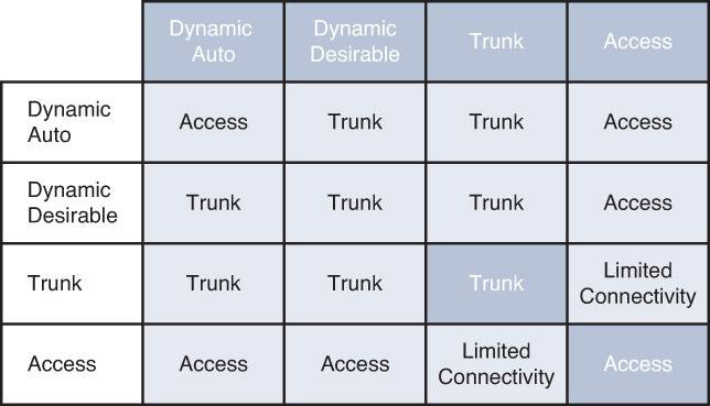
Figure 29-6 DTP Combinations
Notice that Figure 29-6 also includes access as a DTP mode. Using the switchport mode access command puts the interface into a permanent nontrunking mode and negotiates to convert the link into a nontrunking link.
In all these modes, DTP frames are sent out every 30 seconds to keep neighboring switch ports informed of a link’s mode. On critical trunk links in a network, manually configuring the trunking mode on both ends is best so that the link can never be negotiated to any other state.
As a best practice, you should configure both ends of a trunk link as a fixed trunk (switchport mode trunk) or as an access link (switchport mode access) to remove any uncertainty about the link operation. In the case of a trunk, you can disable DTP completely so that the negotiation frames are not exchanged at all. To do this, add the switchport nonegotiate command to the interface configuration. Be aware that after DTP frames are disabled, no future negotiation is possible until this configuration is reversed.
DTP Configuration Example
Figure 29-7 illustrates a topology in which SW1 and SW2 use a combination of DTP modes to establish an 802.1Q trunk.

Figure 29-7 DTP Configuration Example Topology
In this example, SW1 is configured to actively negotiate a trunk with SW2. SW2 is configured to passively negotiate a trunk with SW1. Example 29-9 shows confirmation that an 802.1Q trunk is successfully negotiated.
Example 29-9 Verifying Trunk Status Using DTP
SW1# show interfaces trunk
Port        Mode             Encapsulation  Status        Native vlan
Gi1/0/24    desirable        802.1q         trunking      1

Port        Vlans allowed on trunk
Gi1/0/24    1-4094

Port        Vlans allowed and active in management domain
Gi1/0/24    1-4094

Port        Vlans in spanning tree forwarding state and not pruned
Gi1/0/24    1-4094
SW2# show interfaces trunk
Port        Mode             Encapsulation  Status        Native vlan
Gi1/0/24    auto             802.1q         trunking      1

Port        Vlans allowed on trunk
Gi1/0/24    1-4094

Port        Vlans allowed and active in management domain
Gi1/0/24    1-4094

Port        Vlans in spanning tree forwarding state and not pruned
Gi1/0/24    1-4094
VLAN Trunking Protocol
VLAN Trunking Protocol (VTP) is a Layer 2 protocol that maintains VLAN configuration consistency by managing the additions, deletions, and name changes of VLANs across networks. VTP is organized into management domains, or areas with common VLAN requirements. A switch can belong to only one VTP domain, and it shares VLAN information with other switches in the domain. Switches in different VTP domains, however, do not share VTP information. Switches in a VTP domain advertise several attributes to their domain neighbors. Each advertisement contains information about the VTP management domain, VTP revision number, known VLANs, and specific VLAN parameters. When a VLAN is added to a switch in a management domain, other switches are notified of the new VLAN through VTP advertisements. In this way, all switches in a domain can prepare to receive traffic on their trunk ports using the new VLAN.
VTP Modes
To participate in a VTP management domain, each switch must be configured to operate in one of several modes. The VTP mode determines how the switch processes and advertises VTP information. You can use the following modes:
• Server mode: VTP servers have full control over VLAN creation and modification for their domains. All VTP information is advertised to other switches in the domain, and all received VTP information is synchronized with the other switches. By default, a switch is in VTP server mode. Note that each VTP domain must have at least one server so that VLANs can be created, modified, or deleted and so VLAN information can be propagated.
• Client mode: VTP clients do not allow the administrator to create, change, or delete any VLANs. Instead, they listen to VTP advertisements from other switches and modify their VLAN configurations accordingly. In effect, this is a passive listening mode. Received VTP information is forwarded out trunk links to neighboring switches in the domain, so the switch also acts as a VTP relay.
• Transparent mode: VTP transparent switches do not participate in VTP. While in transparent mode, a switch does not advertise its own VLAN configuration, and it does not synchronize its VLAN database with received advertisements.
• Off mode: Like transparent mode, switches in VTP off mode do not participate in VTP; however, VTP advertisements are not relayed at all. You can use VTP off mode to disable all VTP activity on or through a switch.
Figure 29-8 illustrates a simple network in which SW1 is the VTP server for the domain 31DAYS. SW3 and SW4 are configured as VTP clients, and SW2 is configured as VTP transparent. SW1, SW3, and SW4 have synchronized VLAN databases with VLANs 5, 10, and 15. SW2 has propagated VTP information to SW4, but its own database only contains VLANs 100 and 200.
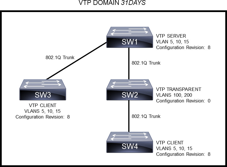
Figure 29-8 VTP Topology Example
VTP advertisements are flooded throughout the management domain. VTP summary advertisements are sent every 5 minutes or whenever there is a change in VLAN configuration. Advertisements are transmitted (untagged) over the native VLAN (VLAN 1 by default) using a multicast frame.
VTP Configuration Revision
One of the most critical components of VTP is the configuration revision number. Each time a VTP server modifies its VLAN information, the VTP server increments the configuration revision number by one. The server then sends out a VTP subset advertisement with the new configuration revision number. If the configuration revision number being advertised is higher than the number stored on the other switches in the VTP domain, the switches overwrite their VLAN configurations with the new information that is being advertised. The configuration revision number in VTP transparent mode is always 0.
A device that receives VTP advertisements must check various parameters before incorporating the received VLAN information. First, the management domain name and password in the advertisement must match the values that configured on the local switch. Next, if the configuration revision number indicates that the message was created after the configuration currently in use, the switch incorporates the advertised VLAN information.
Returning to the example in Figure 29-8, notice that the current configuration revision number is 8. If a network administrator were to add a new VLAN to the VTP server (SW1), the configuration revision number would increment by 1 to a new value of 9. SW1 would then flood a VTP subset advertisement across the VTP domain. SW3 and SW4 would add the new VLAN to their VLAN databases. SW2 would ignore this VTP update.
VTP Versions
Three versions of VTP are available for use in a VLAN management domain. Catalyst switches can run either VTP Version 1, 2, or 3. Within a management domain, the versions are not fully interoperable. Therefore, the same VTP version should be configured on every switch in a domain. Switches use VTP Version 1 by default. Most switches now support Version 3, which offers better security, better VLAN database propagation control, MST support, and extended VLAN ranges to 4094. When using Version 3, the primary VTP server must be configured with the vtp primary privileged EXEC command.
VTP Configuration Example
Figure 29-9 shows a topology in which SW1 is configured as the VTP Version 3 primary server, and SW2 is configured as the VTP client. Both switches are configured for the same VTP domain (31DAYS) and with the same password.
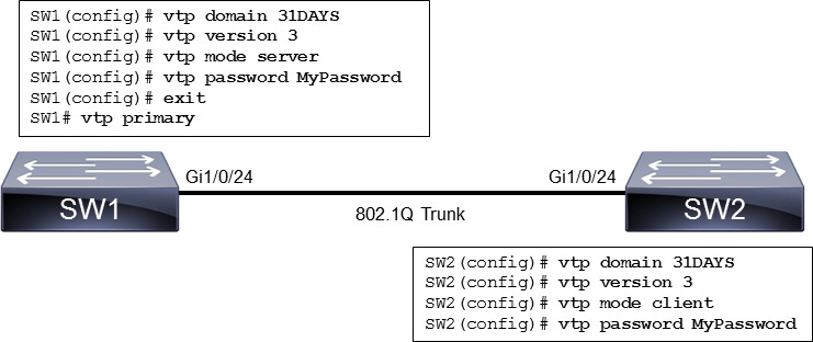
Figure 29-9 VTP Configuration Example
To verify VTP, use the show vtp status command, as shown in Example 29-10.
Example 29-10 Verifying VTP
SW1# show vtp status
VTP Version capable             : 1 to 3
VTP version running             : 3
VTP Domain Name                 : 31DAYS
VTP Pruning Mode                : Disabled
VTP Traps Generation            : Disabled
Device ID                       : acf5.e649.6080

Feature VLAN:
--------------
VTP Operating Mode                : Primary Server
Number of existing VLANs          : 4
Number of existing extended VLANs : 0
Maximum VLANs supported locally   : 4096
Configuration Revision            : 8
Primary ID                        : acf5.e649.6080
Primary Description               : SW1
MD5 digest                        : 0x12 0x7B 0x0A 0x2C 0x00 0xA6 0xFC 0x05
                                    0x56 0xAA 0x50 0x4B 0xDB 0x0F 0xF7 0x37

<. . . output omitted . . .>
SW2# show vtp status
VTP Version capable             : 1 to 3
VTP version running             : 3
VTP Domain Name                 : 31DAYS
VTP Pruning Mode                : Disabled
VTP Traps Generation            : Disabled
Device ID                       : 0062.e24c.c044

Feature VLAN:
--------------
VTP Operating Mode                : Client
Number of existing VLANs          : 4
Number of existing extended VLANs : 0
Maximum VLANs supported locally   : 4096
Configuration Revision            : 8
Primary ID                        : 0062.e24c.c044
Primary Description               : SW2
MD5 digest                        : 0x12 0x7B 0x0A 0x2C 0x00 0xA6 0xFC 0x05
                                    0x56 0xAA 0x50 0x4B 0xDB 0x0F 0xF7 0x37

<. . . output omitted . . .>
In the output in Example 29-10, notice that SW1 and SW2 are on the same configuration revision number and have the same number of existing VLANs.
Inter-VLAN Routing
Recall that a Layer 2 network is defined as a broadcast domain. A Layer 2 network can also exist as a VLAN inside one or more switches. VLANs are essentially isolated from each other so that packets in one VLAN cannot cross into another VLAN.
To transport packets between VLANs, you must use a Layer 3 device. Traditionally, this has been a router’s function. The router must have a physical or logical connection to each VLAN so that it can forward packets between them. This is known as inter-VLAN routing.
Inter-VLAN routing can be performed by an external router that connects to each of the VLANs on a switch. Separate physical connections can be used to achieve this. Part A of Figure 29-10 illustrates this concept. The external router can also connect to the switch through a single trunk link, carrying all the necessary VLANs, as illustrated in Part B of Figure 29-10. Part B illustrates what is commonly referred to as a “router-on-a-stick” because the router needs only a single interface to do its job.
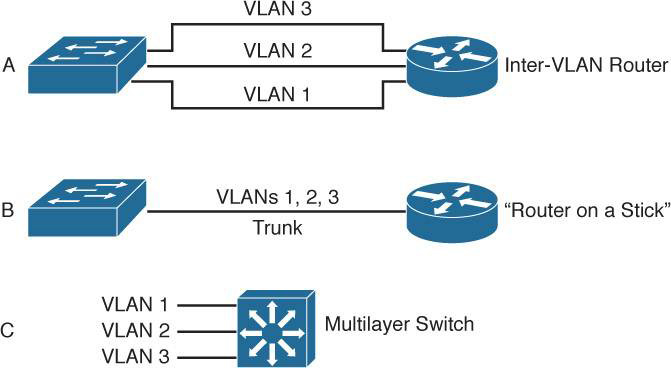
Figure 29-10 Inter-VLAN Routing Models
Finally, Part C of Figure 29-10 shows how the routing and switching functions can be combined into one device: a Layer 3 or multilayer switch. No external router is needed.
Inter-VLAN Routing Using an External Router
Figure 29-11 shows a configuration in which the router is connected to a switch with a single 802.1Q trunk link. The router can receive packets on one VLAN and forward them to another VLAN. In the example, PC1 can send packets to PC2, which is in a different VLAN. To support 802.1Q trunking, you must subdivide the physical router interface into multiple logical, addressable interfaces—one per VLAN. The resulting logical interfaces are called subinterfaces. You associate the VLAN with each subinterface by using the encapsulation dot1q vlan-id command.
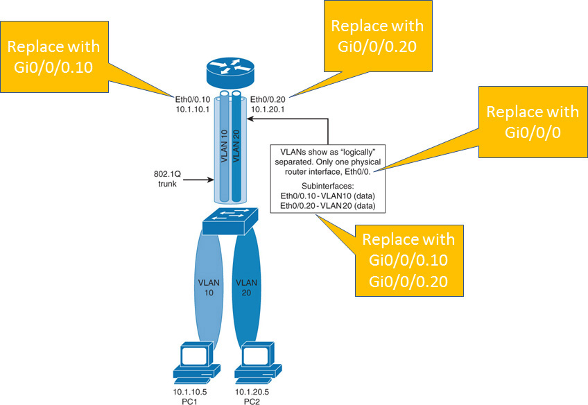
Figure 29-11 Inter-VLAN Routing Using an External Router
Example 29-11 shows the commands required to configure the router-on-stick illustrated in Figure 29-11.
Example 29-11 Configuring Routed Subinterfaces
Router# configure terminal
R1(config)# interface GigabitEthernet 0/0/0.10
R1(config-subif)# encapsulation dot1q 10
R1(config-subif)# ip address 10.0.10.1 255.255.255.0
R1(config-subif)# interface GigabitEthernet 0/0/0.20
R1(config-subif)# encapsulation dot1q 20
R1(config-subif)# ip address 10.0.20.1 255.255.255.0
R1(config-subif)# interface GigabitEthernet 0/0/0.1
R1(config-subif)# encapsulation dot1q 1 native
R1(config-subif)# ip address 10.0.1.1 255.255.255.0
Notice the use of the native keyword in Example 29-11. The other option for configuring routing of untagged traffic is to configure the physical interface with the native VLAN IP address. The disadvantage of such a configuration is that when you do not want the untagged traffic to be routed, you must shut down the physical interface, but in doing so, you also shut down all the subinterfaces on that interface.
Inter-VLAN Routing Using Switched Virtual Interfaces
A switched virtual interface (SVI) is a virtual interface that is configured within a multilayer switch. You can create an SVI for any VLAN that exists on the switch. Only one SVI can be associated with one VLAN. An SVI can be configured to operate at Layer 2 or Layer 3, as shown in Figure 29-12. An SVI is virtual in that there is no physical port dedicated to the interface, yet it can perform the same functions for the VLAN as a router interface would. An SVI can be configured in the same way as a router interface (with IP address, inbound or outbound access control lists, and so on). The SVI for the VLAN provides Layer 3 processing for packets to and from all switch ports that are associated with that VLAN.

Figure 29-12 SVI on a Layer 3 Switch
By default, an SVI is created for the default VLAN (VLAN 1) to permit remote switch administration. Additional SVIs must be explicitly created. You create SVIs the first time that you enter the VLAN interface configuration mode for a particular VLAN SVI (for example, when you enter the global configuration command interface vlan vlan-id). The VLAN number that you use should correspond to the VLAN tag associated with the data frames on an 802.1Q encapsulated trunk or with the VID that is configured for an access port. You can configure and assign an IP address for each VLAN SVI that is to route traffic from and into a VLAN on a Layer 3 switch.
Example 29-12 shows the commands required to configure the SVIs in Figure 29-12. The example assumes that VLAN 10 and VLAN 20 are already preconfigured.
Example 29-12 Configuring SVIs
SW1# configure terminal
SW1(config)# interface vlan 10
SW1(config-if)# ip address 10.0.10.1 255.255.255.0
SW1(config-if)# no shutdown
SW1(config-if)# interface vlan 20
SW1(config-if)# ip address 10.0.20.1 255.255.255.0
SW1(config-if)# no shutdown
Routed Switch Ports
A routed switch port is a physical switch port on a multilayer switch that is configured to perform Layer 3 packet processing. You configure a routed switch port by removing the Layer 2 switching capability of the switch port. Unlike an access port or an SVI, a routed port is not associated with a particular VLAN. Also, because Layer 2 functionality has been removed, Layer 2 protocols such as STP and VTP do not function on a routed interface. However, protocols like LACP, which can be used to build either Layer 2 or Layer 3 EtherChannel bundles, still function at Layer 3.
Routed ports are used for point-to-point links; for example, routed ports may be used to connect WAN routers and to connect security devices. In a campus switched network, routed ports are mostly configured between switches in the campus backbone and building distribution switches if Layer 3 routing is applied at the distribution layer. If Layer 3 routing is deployed at the access layer, then links from access to distribution also use routed switch ports.
To configure routed ports, you configure the respective interface as a Layer 3 interface by using the no switchport interface command if the default configurations of the interfaces are Layer 2 interfaces. In addition, you can assign an IP address and other Layer 3 parameters as necessary.
Example 29-13 shows the commands required to configure Gigabit Ethernet 1/0/23 as a Layer 3 routed switch port.
Example 29-13 Configuring Routed Switch Ports
SW1# configure terminal
SW1(config)# interface GigabitEthernet 1/0/23
SW1(config-if)# no switchport
SW1(config-if)# ip address 10.254.254.1 255.255.255.0
Study Resources
For today’s exam topics, refer to the following resources for more study.
