Day 25. OSPFv2
ENCOR 350-401 Exam Topics
• Infrastructure
• Configure and verify simple OSPF environments, including multiple normal areas, summarization, and filtering (neighbor adjacency, point-to-point and broadcast network types, and passive interface)
Key Topics
Today we start our review of the Open Shortest Path First (OSPF) routing protocol. OSPF is a vendor-agnostic link-state routing protocol that builds and maintains the routing tables needed for IPv4 and IPv6 traffic. Today we focus on OSPFv2 (RFC 2328), which works only with IPv4. The most recent implementation of OSPF, OSPFv3, works with both IPv4 and IPv6. OSPFv3 is discussed on Day 24, “Advanced OSPFv2 and OSPFv3.” Both versions of OSPF are open standards and can run on various devices that need to manage routing tables. Devices such as traditional routers, multilayer switches, servers, and firewalls can benefit from running OSPF. The shortest path first (SPF) algorithm lives at the heart of OSPF. The algorithm, developed by Edsger Wybe Dijkstra in 1956, is used by OSPF to provide IP routing with high-speed convergence in a loop-free topology. OSPF provides fast convergence by using triggered, incremental updates that exchange link-state advertisements (LSAs) with neighboring OSPF routers. OSPF is a classless protocol, meaning it carries the subnet mask with all IP routes. It supports a structured two-tiered hierarchical design model using a backbone and other connected areas. This hierarchical design model is used to scale larger networks to further improve convergence time, to create smaller failure domains, and to reduce the complexity of the network routing tables.
OSPF Characteristics
OSPF is a link-state routing protocol. You can think of a link as an interface on a router. The state of the link is a description of that interface and of its relationship to its neighboring routers. A description of the interface would include, for example, the IP address of the interface, the subnet mask, the type of network to which it is connected, the routers that are connected to that network, and so on. The collection of all these link states forms a link-state database.
OSPF performs the following functions, as illustrated in Figure 25-1:
• Creates a neighbor relationship by exchanging hello packets
• Propagates LSAs rather than routing table updates:
• Link: Router interface
• State: Description of an interface and its relationship to neighboring routers
• Floods LSAs to all OSPF routers in the area, not just the directly connected routers
• Pieces together all the LSAs that OSPF routers generate to create the OSPF link-state database
• Uses the SPF algorithm to calculate the shortest path to each destination and places it in the routing table
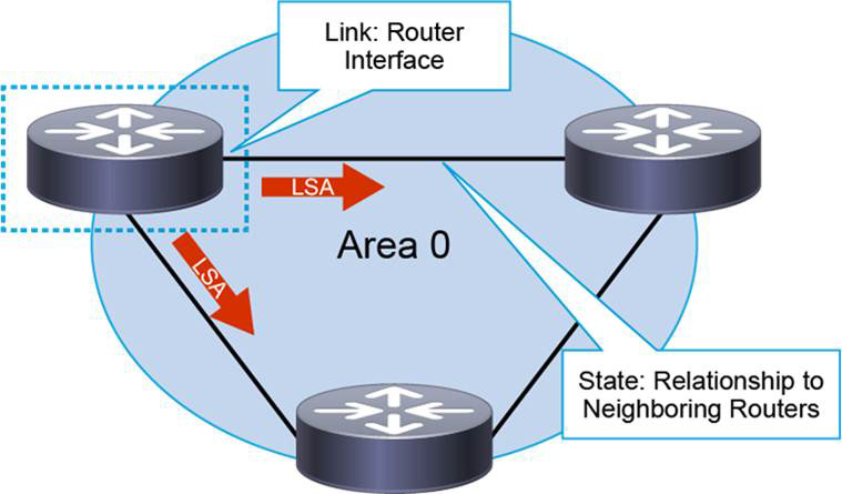
Figure 25-1 OSPF Functionality
A router sends LSA packets immediately to advertise its state when there are state changes. The router sends the packets periodically as well (every 30 minutes by default). The information about the attached interfaces, the metrics that are used, and other variables are included in OSPF LSAs. As OSPF routers accumulate link-state information, they use the SPF algorithm to calculate the shortest path to each node.
A topological (link-state) database is, essentially, an overall picture of the networks in relationship to the other routers. The topological database contains the collection of LSAs that all routers in the same area have sent. Because the routers in the same area share the same information, they have identical topological databases.
OSPF can operate within a hierarchy. The largest entity in the hierarchy is the autonomous system (AS), which is a collection of networks under a common administration that shares a common routing strategy. An AS can be divided into several areas, which are groups of contiguous networks and attached hosts. Within each AS, a contiguous backbone area must be defined as Area 0. In a multiarea design, all other nonbackbone areas are connected off the backbone area. A multiarea design is effective because the network is segmented to limit the propagation of LSAs inside an area. It is especially useful for large networks. Figure 25-2 illustrates the two-tier hierarchy that OSPF uses in an AS.
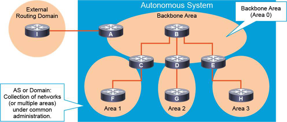
Figure 25-2 OSPF Backbone and Nonbackbone Areas in an AS
OSPF Process
Enabling the OSPF process on a device is straightforward. OSPF is started with the same router ospf process-id command on enterprise routers, multilayer switches, and firewalls. This action requires the configuration of a process ID, which is a value that indicates a unique instance of the OSPF protocol for the device. While this numeric value is needed to start the process, it is not used outside the device on which it is configured, and it is only locally significant (that is, this value is not used for communicating with other OSPF routers). Having one router use OSPF process 10 while a neighboring router uses process 1 will not hinder the establishment of OSPF neighbor relationships. However, for ease of administration, it is best practice to use the same process ID for all devices in the same AS, as shown in Figure 25-3.

Figure 25-3 OSPF Process ID
It is possible to have multiple instances of OSPF running on a single router, as illustrated in Figure 25-4. This might be desirable in a situation where two organizations are merging together, and both are running OSPF. The routers designated to merge these two organizations would run an instance of OSPF to communicate to “Group A” and a separate instance for "Group B.” The router could redistribute the routing data between the OSPF processes. Another situation in which multiple OSPF processes might be used on a single router is in a service provider’s implementation of MPLS. However, it is generally uncommon to need multiple OSPF processes on a router.

Figure 25-4 OSPF Multiple Process IDs
Once the process is started, the OSPF router is assigned a router ID. This ID value is a 32-bit number that is written like an IP address. The ID value is not required to be a valid IP address, but using a valid IP address makes troubleshooting OSPF easier. Whenever the router advertises routes within OSPF, it uses this router ID to mark it as the originator of the routes. Therefore, it is important to ensure that each router within an OSPF network has a unique router ID.
The router ID selection process occurs when the router ospf command is entered. Ideally, the command router-id router-id is used under the OSPF process. If the device does not have an explicit ID assignment, OSPF designates a router ID based on one of the IP addresses (the highest IP address) assigned to the interfaces of the router. If a loopback interface has been created and is active, OSPF uses the IP address of the loopback interface as the router ID. If multiple loopback interfaces are created, OSPF chooses the loopback interface with the numerically highest IP address to use as the router ID. In the absence of loopback interfaces, OPSF chooses an active physical interface with the highest IP address to use for the router ID.
Figure 25-5 shows the configuration of loopback interfaces and the router ID on R1 and R2. The best practice before starting OSPF is to first create a loopback interface and assign it an IP address. Start the OSPF process and then use the router-id router-id command, entering the IP address of the loopback interface as the router ID.

Figure 25-5 OSPF Router ID Configuration
OSPF Neighbor Adjacencies
Neighbor OSPF routers must recognize each other on the network before they can share information because OSPF routing depends on the status of the link between two routers. Hello messages initiate and maintain this process. OSPF routers send hello packets on all OSPF-enabled interfaces to determine whether there are any neighbors on those links.
The Hello protocol establishes and maintains neighbor relationships by ensuring bidirectional (two-way) communication between neighbors.
Each interface that participates in OSPF uses the multicast address 224.0.0.5 to periodically send hello packets. As shown in Figure 25-6, a hello packet contains the following information:
• Router ID: The router ID is a 32-bit number that uniquely identifies the router.
• Hello and dead intervals: The hello interval specifies the frequency, in seconds, at which a router sends hello packets. The default hello interval on multiaccess networks is 10 seconds. The dead interval is the time, in seconds, that a router waits to hear from a neighbor before declaring the neighboring router out of service. By default, the dead interval is four times the hello interval, or 40 seconds. These timers must be the same on neighboring routers; otherwise, an adjacency is not established.
• Neighbors: The Neighbors field lists the adjacent routers with an established bidirectional communication. This bidirectional communication is indicated when the router recognizes itself when it is listed in the Neighbors field of the hello packet from the neighbor.
• Area ID: To communicate, two routers must share a common segment, and their interfaces must belong to the same OSPF area on that segment. The neighbors must also share the same subnet and mask. These routers in the same area all have the same link-state information for that area.
• Router priority: The router priority is an 8-bit number that indicates the priority of a router. OSPF uses the priority to select a designated router (DR) and a backup designated router (BDR). In certain types of networks, OSPF elects DRs and BDRs. The DR acts as a pseudonode or virtual router to reduce LSA traffic between routers and reduce the number of OSPF adjacencies on the segment.
• DR and BDR IP addresses: These addresses are the IP addresses of the DR and BDR for the specific network, if they are known and/or needed, based on the network type.
• Authentication data: If router authentication is enabled, two routers must exchange the same authentication data. Authentication is not required, but it is highly recommended. If it is enabled, all peer routers must have the same key configured.
• Stub area flag: A stub area is a special area. Designating a stub area is a technique that reduces routing updates by replacing them with a default route. Two routers must also agree on the stub area flag in the hello packets to become neighbors.
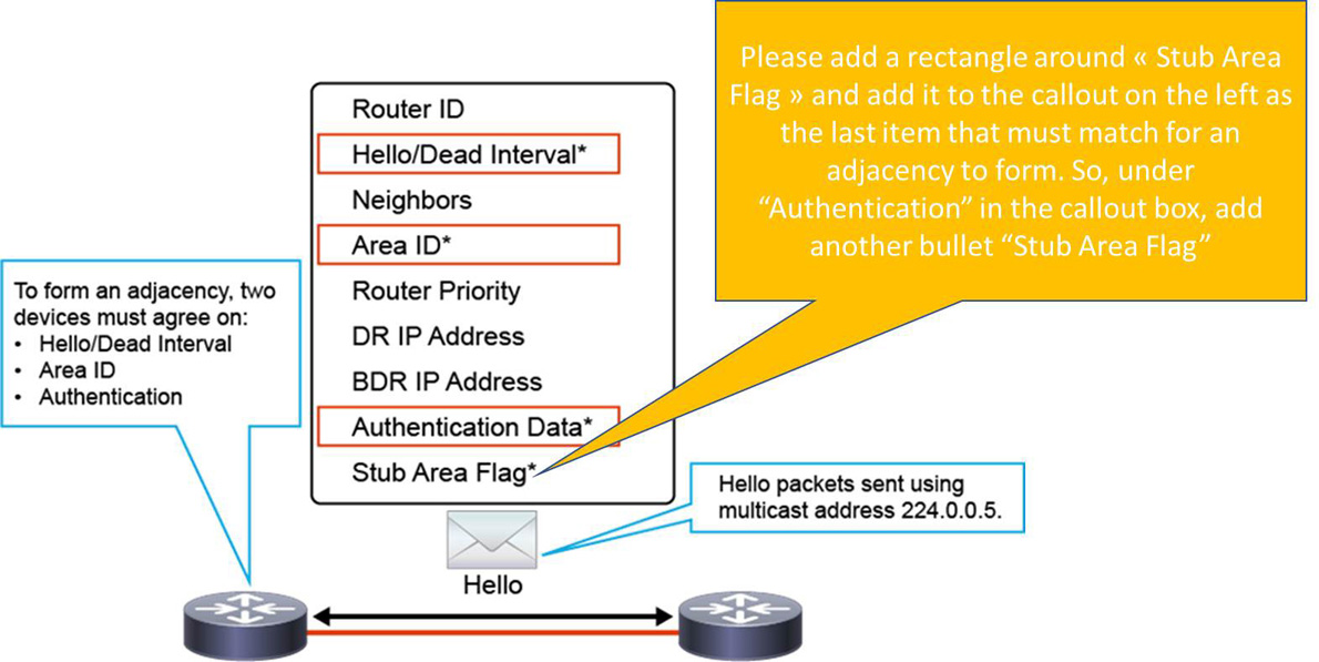
Figure 25-6 OSPF Hello Message
OSPF neighbor adjacencies are critical to the operation of OSPF. OSPF proceeds to the phase of exchanging the routing database following the discovery of a neighbor. In other words, without a neighbor relationship, OSPF cannot route traffic. It is important to ensure that the hello/dead timers, area IDs, authentication, and stub area flag information are consistent and match within the hello messages for all devices that intend to establish OSPF neighbor relationships. The neighboring routers must have the same values set for these options.
Building a Link-State Database
When two routers discover each other and establish adjacency by using hello packets, they then exchange information about LSAs. As shown in Figure 25-7, this process operates as follows:
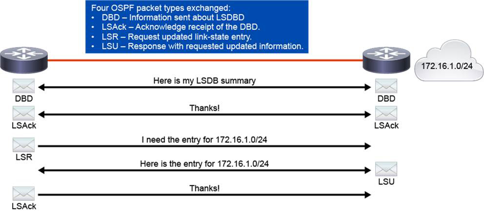
Figure 25-7 OSPF LSDB Sync
1. The routers exchange one or more DBD (database description or type 2 OSPF) packets. A DBD includes information about the LSA entry header that appears in the link-state database (LSDB) of the router. Each LSA entry header includes information about the link-state type, the address of the advertising router, the cost of the link, and the sequence number. The router uses the sequence number to determine the "newness" of the received link-state information.
2. When the router receives the DBD, it acknowledges the receipt of the DBD that is using the link-state acknowledgment (LSAck) packet.
3. The routers compare the information they receive with the information they have. If the received DBD has a more up-to-date link-state entry, the router sends a link-state request (LSR) to the other router to request the updated link-state entry.
4. The other router responds with complete information about the requested entry in a link-state update (LSU) packet. The LSU contains one or more LSAs. The other router adds the new link-state entries to its LSDB.
5. Finally, when the router receives an LSU, it sends an LSAck.
OSPF Neighbor States
OSPF neighbors go through multiple neighbor states before forming a full OSPF adjacency, as illustrated in Figure 25-8.
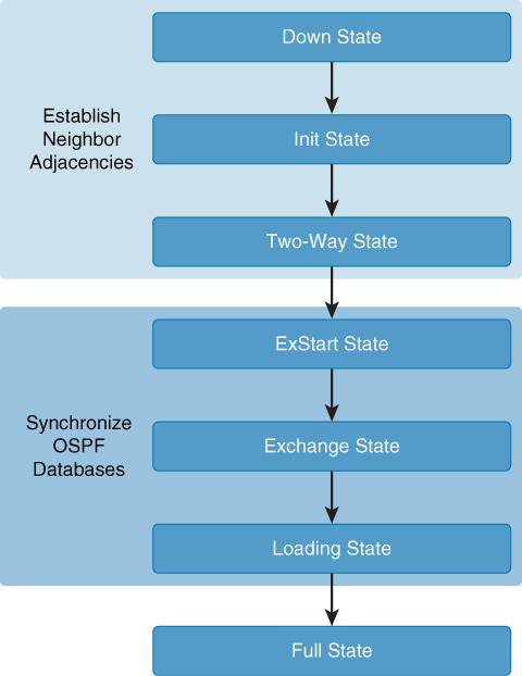
Figure 25-8 OSPF Neighbor States
The following is a summary of the states that an interface passes through before establishing as adjacency with another router:
• Down: No information has been received on the segment.
• Init: The interface has detected a hello packet coming from a neighbor, but bidirectional communication has not yet been established.
• 2-Way: There is bidirectional communication with a neighbor. The router has seen itself in the hello packets coming from a neighbor. At the end of this stage, the DR and BDR election will be performed if necessary. When routers are in the 2-WAY state, they must decide whether to proceed in building an adjacency. The decision is based on whether one of the routers is a DR or BDR or if the link is a point-to-point link or a virtual link.
• ExStart: Routers try to establish the initial sequence number that is going to be used in the information exchange packets. The sequence number ensures that routers always get the most recent information. One router becomes the master, and the other becomes the slave. The master router polls the slave for information.
• Exchange: Routers describe their entire LSDB by sending database description (DBD) packets. In this state, packets may be flooded to other interfaces on the router.
• Loading: In this state, routers finalize the information exchange. Routers have built a link-state request list and a link-state retransmission list. Any information that looks incomplete or outdated is be put on the request list. Any update that is sent is put on the retransmission list until it gets acknowledged.
• Full: In this state, adjacency is complete. The neighboring routers are fully adjacent. Adjacent routers have similar LSDBs.
OSPF Packet Types
Table 25-1 describes the OSPF packet type.
Table 25-1 OSPF Packet Types
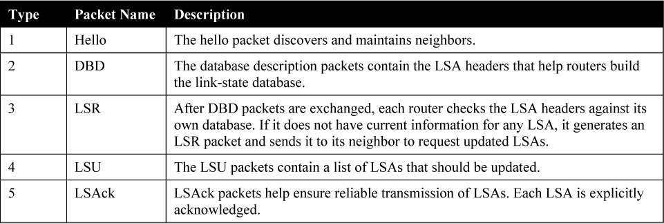
OSPF uses five types of routing protocol packets that share a common protocol header. The Protocol field in the IP header is set to 89. All five packet types are used in normal OSPF operation. All five OSPF packet types are encapsulated directly into an IP payload, as shown in Figure 25-9. OSPF packets do not use TCP or UDP. OSPF requires a reliable packet transport, but because it does not use TCP, OSPF defines an acknowledgment packet (OSPF packet type 5) to ensure reliability.
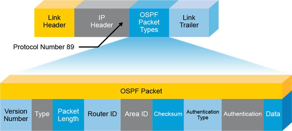
Figure 25-9 OSPF Packet Encapsulation
OSPF LSA Types
Knowing the detailed topology of the OSPF area is a prerequisite for a router to calculate the best paths. Topology details are described by LSAs carried inside LSUs, which are the building blocks of the OSPF LSDB. Individually, LSAs act as database records. In combination, they describe the entire topology of an OSPF network area. Table 25-2 lists the most common LSA types, and the following list describes them:
Table 25-2 OSPF LSA Types

• Type 1: Every router generates type 1 router LSAs for each area to which it belongs. Router LSAs describe the state of the router links to the area and are flooded only within that particular area. The LSA header contains the link-state ID of the LSA. The link-state ID of the type 1 LSA is the originating router ID.
• Type 2: DRs generate type 2 network LSAs for multiaccess networks. Network LSAs describe the set of routers that are attached to a particular multiaccess network. Network LSAs are flooded in the area that contains the network. The link-state ID of the type 2 LSA is the IP interface address of the DR.
• Type 3: An ABR takes the information that it learned in one area and describes and summarizes it for another area in the type 3 summary LSA. This summarization is not on by default. The link-state ID of the type 3 LSA is the destination network number.
• Type 4: The type 4 ASBR summary LSA tells the rest of the OSPF domain how to get to the ASBR. The link-state ID includes the router ID of the described ASBR.
• Type 5: Type 5 AS external LSAs, which are generated by ASBRs, describe routes to destinations that are external to the AS. They get flooded everywhere except into special areas. The link-state ID of the type 5 LSA is the external network number.
• Type 6: These specialized LSAs are used in multicast OSPF applications.
• Type 7: Type 7 LSAs are used in NSSA special area type for external routes.
• Type 8 and type 9: Type 8 and 9 LSAs are used in OSPFv3 for link-local addresses and intra-area prefixes.
• Type 10 and type 11: Type 10 and 1010 LSAs are generic LSAs, also called opaque, which allow future extensions of OSPF.
Figure 25-10 shows an example of LSA propagation in which R2 is an ABR between Area 0 and Area 1. R3 acts as the ASBR between the OSPF routing domain and an external domain. LSA types 1 and 2 are flooded between routers within an area. Type 3 and type 5 LSAs are flooded when exchanging information between the backbone and standard areas. Type 4 LSAs are injected into the backbone by the ABR because all routers in the OSPF domain need to reach the ASBR (R3).
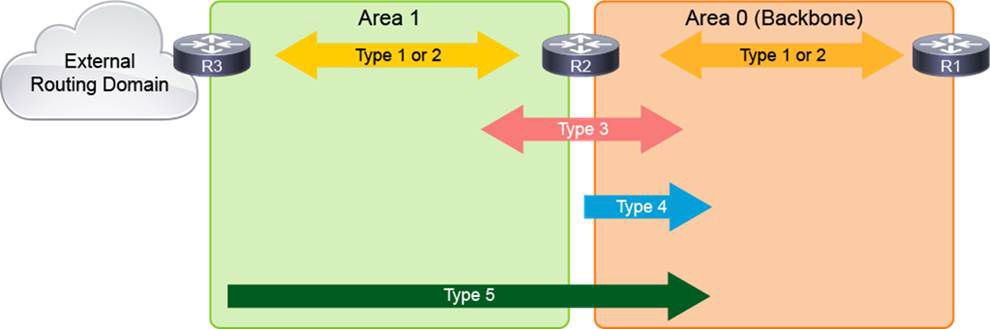
Figure 25-10 OSPF LSA Propagation
Single-Area and Multiarea OSPF
The single-area OSPF design has all routers in a single OSPF area. This design results in many LSAs being processed on every router and in larger routing tables. This OSPF configuration follows a single-area design in which all the routers are treated as being internal routers to the area, and all the interfaces are members of this single area.
Keep in mind that OSPF uses flooding to exchange link-state updates between routers. Any change in the routing information is flooded to all routers in an area. For this reason, the single-area OSPF design can become undesirable as the network grows. The number of LSAs that are processed on every router increases, and the routing tables may grow very large.
For enterprise networks, a multiarea design is a better solution than a single-area design. In a multiarea design, the network is segmented to limit the propagation of LSAs inside an area and to make the routing tables smaller by utilizing summarization. In Figure 25-11, an area border router (ABR) is configured between two areas (Area 0 and Area 1). The ABR can provide summarization of routes between the two areas and can acts as a default gateway for all Area 1 internal routers (R4, R5, and R6).
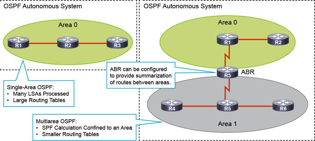
Figure 25-11 OSPF Single-Area and Multiarea
There are two types of routers from a configuration point of view, as illustrated in Figure 25-12:
• Routers with single-area configuration: Internal routers (R5, R6), the backbone router (R1), and autonomous system border routers (ASBRs) that reside in one area.
• Routers with a multiarea configuration: Area border routers (ABRs) and ASBRs that reside in more than one area.
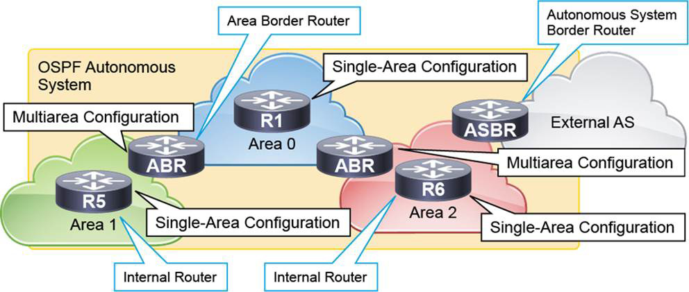
Figure 25-12 OSPF Router Roles
OSPF Area Structure
As mentioned earlier, OSPF uses a two-tiered area hierarchy. Figure 25-13 illustrates the two areas in this hierarchy:
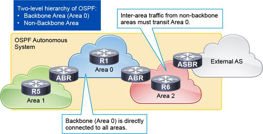
Figure 25-13 OSPF Hierarchy
• Backbone area (Area 0): The primary function of this OSPF area is to quickly and efficiently move IP packets. Backbone areas interconnect with other OSPF area types. The OSPF hierarchical area structure requires that all areas connect directly to the backbone area. Interarea traffic must traverse the backbone.
• Normal, or nonbackbone, area: The primary function of this OSPF area is to connect users and resources. Normal areas are usually set up according to functional or geographic groupings. By default, a normal area does not allow traffic from another area to use its links to reach other areas. All interarea traffic from other areas must cross a transit area such as Area 0.
All OSPF areas and routers that are running the OSPF routing protocol compose the OSPF AS.
The routers that are configured in Area 0 are known as backbone routers. If a router has any interface(s) in Area 0, it is considered a backbone router. Routers that have all their interfaces in a single area are called internal routers because they have to manage only a single LSDB each.
An ABR connects multiple areas together. Normally, this configuration is used to connect Area 0 to the nonbackbone areas. An OSPF ABR plays a very important role in the network design and has interfaces in more than one area. An ABR has the following characteristics:
• It separates LSA flooding zones.
• It becomes the primary point for area address summarization.
• It can designate a nonbackbone area to be a special area type, such as a stub area.
• It maintains the LSDB for each area with which it is connected.
An ASBR connects any OSPF area to a different routing domain. The ASBR is the point where external routes can be introduced into the OSPF AS. Essentially, routers act as an ASBR if routes are introduced into the AS using route redistribution or if the OSPF router is originating the default route. ASBR routers can live in the backbone area or in the nonbackbone area. A device running OSPF can act as an ASBR and as an ABR concurrently.
OSPF Network Types
OSPF defines distinct types of networks, based on the physical link types. OSPF operation is different in each type of network, including how adjacencies are established and which configuration is required. Table 25-3 summarizes the characteristics of the OSPF network types.
Table 25-3 OSPF Network Types
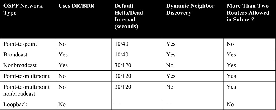
The following are the network types most commonly defined by OSPF:
• Point-to-point: Routers use multicast to dynamically discover neighbors. There is no DR/BDR election because only two routers can be connected on a single point-to-point segment. This is a default OSPF network type for serial links and point-to-point Frame Relay subinterfaces.
• Broadcast: Multicast is used to dynamically discover neighbors. The DR and BDR are elected to optimize the exchange of information. This is a default OSPF network type for multiaccess Ethernet links.
• Nonbroadcast: This network type is used on networks that interconnect more than two routers but without broadcast capability. Frame Relay and Asynchronous Transfer Mode (ATM) are examples of nonbroadcast multiaccess (NBMA) networks. Neighbors must be statically configured, and then DR/BDR election occurs. This network type is the default for all physical interfaces and multipoint subinterfaces using Frame Relay encapsulation.
• Point-to-multipoint: OSPF treats this network type as a logical collection of point-to-point links, although all interfaces belong to the common IP subnet. Every interface IP address appears in the routing table of the neighbors as a host /32 route. Neighbors are discovered dynamically using multicast. There is no DR/BDR election.
• Point-to-multipoint nonbroadcast: This network type is a Cisco extension that has the same characteristics as point-to-multipoint, except that neighbors are not discovered dynamically. Neighbors must be statically defined, and unicast is used for communication. This network type can be useful in point-to-multipoint scenarios where multicast and broadcasts are not supported.
• Loopback: This is the default network type on loopback interfaces.
OSPF DR and BDR Election
Multiaccess networks, either broadcast (such as Ethernet) or nonbroadcast (such as Frame Relay), present interesting issues for OSPF. All routers sharing the common segment are part of the same IP subnet. When forming adjacency on a multiaccess network, every router tries to establish full OSPF adjacency with all other routers on the segment. This behavior may not be an issue for smaller multiaccess broadcast networks, but it may be an issue for the NBMA, where, usually, you do not have a full-mesh PVC topology. This issue in NBMA networks manifests in the inability for neighbors to synchronize their OSPF databases directly among themselves. A logical solution, in this case, is to have a central point of OSPF adjacency responsible for the database synchronization and advertisement of the segment to the other routers.
As the number of routers on the segment grows, the number of OSPF adjacencies increases exponentially. Every router must synchronize its OSPF database with every other router, and if there are many routers on a segment, this behavior leads to inefficiency. Another issue arises when every router on the segment advertises all its adjacencies to other routers in the network. If you have full-mesh OSPF adjacencies, the other OSPF routers receive a large amount of redundant link-state information. The solution for this problem is again to establish a central point with which every other router forms an adjacency and advertises the segment to the rest of the network.
The routers on the multiaccess segment elect a DR and a BDR that centralize communication for all routers connected to the segment. The DR and BDR improve network functionality in the following ways:
• Reducing routing update traffic: The DR and BDR act as a central point of contact for link-state information exchange on a multiaccess network. Therefore, each router must establish a full adjacency with the DR and the BDR. Each router, rather than exchanging link-state information with every other router on the segment, sends the link-state information to the DR and BDR only by using the dedicated multicast address 224.0.0.6. The DR represents the multiaccess network in the sense that it sends link-state information from each router to all other routers in the network. This flooding process significantly reduces the router-related traffic on the segment.
• Managing link-state synchronization: The DR and BDR ensure that the other routers on the network have the same link-state information about the common segment. In this way, the DR and BDR reduce the number of routing errors.
When the DR is operating, the BDR does not perform any DR functions. Instead, the BDR receives all the information, but the DR performs the LSA forwarding and LSDB synchronization tasks. The BDR performs the DR tasks only if the DR fails. When the DR fails, the BDR automatically becomes the new DR, and a new BDR election occurs.
When routers start establishing OSPF neighbor adjacencies, they first send OSPF hello packets to discover which OSPF neighbors are active on the common Ethernet segment. After the bidirectional communication between routers is established and they are all in OSPF neighbor 2-WAY state, the DR/BDR election process begins.
One of the fields in the OSPF hello packet that is used in the DR/BDR election process is the Router Priority field. Every broadcast and nonbroadcast multiaccess OSPF-enabled interface has an assigned priority value, which is a number between 0 and 255. By default, in Cisco IOS Software, the OSPF interface priority value is 1. You can manually change it using the ip ospf priority interface-level command. To elect a DR, and BDR, the routers view the OSPF priority value of other routers during the hello packet exchange process and then use the following conditions to determine which router to select:
• The router with the highest priority value is elected as the DR.
• The router with the second-highest priority value is the BDR.
• If there is a tie, where two routers have the same priority value, the router ID is used as the tiebreaker. The router with the highest router ID becomes the DR. The router with the second-highest router ID becomes the BDR.
• A router with a priority that is set to 0 cannot become the DR or BDR. A router that is not the DR or BDR is called a DROTHER.
The DR/BDR election process takes place on broadcast and nonbroadcast multiaccess networks. The main difference between the two is the type of IP address that is used in the hello packet. On multiaccess broadcast networks, routers use multicast destination IP address 224.0.0.6 to communicate with the DR (called AllDRRouters), and the DR uses multicast destination IP address 224.0.0.5 to communicate with all other non-DR routers (called AllSPFRouters). On NBMA networks, the DR and adjacent routers communicate using unicast.
The DR/BDR election procedure occurs not only when the network first becomes active, and it also occurs when the DR becomes unavailable. In this case, the BDR immediately becomes the DR, and the election of the new BDR starts.
Figure 25-14 illustrates the OSPF DR and BDR election process. The router with a priority of 3 is chosen as DR, and the router with a priority of 2 is chosen as BDR. Notice that R3 has a priority value of 0. This places it in a permanent DROTHER state.
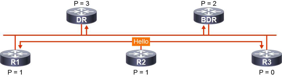
Figure 25-14 OSPF DR and BDR Election
OSPF Timers
Like EIGRP, OSPF uses two timers to check neighbor reachability. These two timers are named the hello and dead timers. The values of the hello and dead intervals are carried in the OSPF hello packet, which serves as a keepalive message that acknowledges the router’s presence on the segment. The hello interval specifies the frequency at which OSPF hello packets are sent, in seconds. The SPF dead timer specifies how long a router waits to receive a hello packet before it declares the neighbor router down.
OSPF requires that both the hello and dead timers be identical for all routers on the segment to become OSPF neighbors. The default value of the OSPF hello timer on multiaccess broadcast and point-to-point links is 10 seconds, and on all other network types, including NBMA, it is 30 seconds. Once you set up the hello interval, the default value of the dead interval is automatically four times the hello interval. For broadcast and point-to-point links, it is 40 seconds, and for all other OSPF network types, it is 120 seconds.
To detect topological changes more quickly, you can lower the value of the OSPF hello interval; the downside is more routing traffic on the link.
The OSPF timers can be changed by using the ip ospf hello-interval and ip ospf dead-interval interface configuration commands.
Multiarea OSPF Configuration
Figure 25-15 illustrates the topology used for the multiarea OSPF example that follows. R1, R4, and R5 are connected to a common multiaccess Ethernet segment. R1 and R2 are connected over a point-to-point serial link. R1 and R3 are connected over an Ethernet WAN link. All routers are configured with the correct physical and logical interfaces and IP addresses. The OSPF router ID is configured to match the individual router’s Loopback 0 interface. Example 25-1 shows the basic multiarea OSPF configuration for all five routers.

Figure 25-15 Multiarea OSPF Basic Configuration Example
Example 25-1 Configuring Multiarea OSPF
R1(config)# router ospf 1
R1(config-router)# network 192.168.1.0.0 0.0.0.255 area 0
R1(config-router)# network 172.16.145.0 0.0.0.7 area 0
R1(config-router)# network 172.16.12.0 0.0.0.3 area 1
R1(config-router)# network 172.16.13.0 0.0.0.3 area 2
R1(config-router)# router-id 192.168.1.1
R2(config)# router ospf 1
R2(config-router)# network 172.16.12.0 0.0.0.3 area 1
R2(config-router)# network 192.168.2.0 0.0.0.255 area 1
R1(config-router)# router-id 192.168.2.1
R3(config)# router ospf 1
R3(config-router)# network 172.16.13.2 0.0.0.0 area 2
R3(config-router)# interface Loopback 0
R3(config-if)# ip ospf 1 area 2
R1(config-router)# router-id 192.168.3.1
R4(config)# router ospf 1
R4(config-router)# network 172.16.145.0 0.0.0.7 area 0
R4(config-router)# network 192.168.4.0 0.0.0.255 area 0
R4(config-router)# router-id 192.168.4.1
R5(config)# router ospf 1
R5(config-router)# network 172.16.145.0 0.0.0.7 area 0
R5(config-router)# network 192.168.5.0 0.0.0.255 area 0
R5(config-router)# router-id 192.168.5.1
To enable the OSPF process on the router, use the router ospf process-id command.
There are multiple ways to enable OSPF on an interface. To define interfaces on which OSPF process runs and to define the area ID for those interfaces, use the network ip-address wildcard-mask area area-id command. The combination of ip-address and wildcard-mask allows you to define one or multiple interfaces to be associated with a specific OSPF area using a single command.
Notice on R3 the use of the 0.0.0.0 wildcard mask with the network command. This mask indicates that only the interface with the specific IP address listed is enabled for OSPF.
Another method exists for enabling OSPF on an interface. R3’s Loopback 0 interface is included in area 2 by using the ip ospf process-id area area-id command. This method explicitly adds the interface to area 2 without the use of the network command. This capability simplifies the configuration of unnumbered interfaces with different areas and ensures that any new interfaces brought online would not automatically be included in the routing process. This configuration method is also used for OSPFv3 since that routing protocol doesn’t allow the use of the network statement.
The router-id command is used on each router to hard code the Loopback 0 IP address as the OSPF router ID.
Verifying OSPF Functionality
You can use the following show commands to verify how OSPF is behaving:
• show ip ospf interface [brief]
• show ip ospf neighbor
• show ip route ospf
Example 25-2 shows these commands applied to the previous configuration example.
Example 25-2 Verifying Multiarea OSPF
R1# show ip ospf interface
Loopback0 is up, line protocol is up
  Internet Address 192.168.1.1/24, Area 0, Attached via Network Statement
  Process ID 1, Router ID 192.168.1.1, Network Type LOOPBACK, Cost: 1
  Topology-MTID    Cost    Disabled    Shutdown      Topology Name
        0           1         no          no            Base
  Loopback interface is treated as a stub Host
GigabitEthernet0/1 is up, line protocol is up
  Internet Address 172.16.145.1/29, Area 0, Attached via Network Statement
  Process ID 1, Router ID 192.168.1.1, Network Type BROADCAST, Cost: 10
  Topology-MTID    Cost    Disabled    Shutdown      Topology Name
        0           10        no          no            Base
  Transmit Delay is 1 sec, State DROTHER, Priority 1
  Designated Router (ID) 192.168.5.1, Interface address 172.16.145.5
  Backup Designated router (ID) 192.168.4.1, Interface address 172.16.145.4
  Timer intervals configured, Hello 10, Dead 40, Wait 40, Retransmit 5
    oob-resync timeout 40
    Hello due in 00:00:05
<. . . output omitted . . .>
Serial2/0 is up, line protocol is up
  Internet Address 172.16.12.1/30, Area 1, Attached via Network Statement
  Process ID 1, Router ID 192.168.1.1, Network Type POINT_TO_POINT, Cost: 64
<. . . output omitted . . .>
GigabitEthernet0/0 is up, line protocol is up
  Internet Address 172.16.13.1/30, Area 2, Attached via Network Statement
  Process ID 1, Router ID 192.168.1.1, Network Type BROADCAST, Cost: 10
<. . . output omitted . . .>
R1# show ip ospf interface brief
Interface    PID   Area            IP Address/Mask    Cost  State Nbrs F/C
Lo0          1     0               192.168.1.1/24     1     LOOP  0/0
Gi0/1        1     0               172.16.145.1/29    1     DROTH 2/2
Se2/0        1     1               172.16.12.1/30     64    P2P   1/1
Gi0/0        1     2               172.16.13.1/30     1     BDR   1/1
R1# show ip ospf neighbor

Neighbor ID     Pri   State           Dead Time   Address         Interface
192.168.4.1       1   FULL/BDR        00:00:33    172.16.145.4    GigabitEthernet0/1
192.168.5.1       1   FULL/DR         00:00:36    172.16.145.5    GigabitEthernet0/1
192.168.2.1       1   FULL/ -         00:01:53    172.16.12.2     Serial2/0
192.168.3.1       1   FULL/DR         00:00:36    172.16.13.2     GigabitEthernet0/0
R4# show ip route ospf
Codes: L - local, C - connected, S - static, R - RIP, M - mobile, B - BGP
       D - EIGRP, EX - EIGRP external, O - OSPF, IA - OSPF inter area
       N1 - OSPF NSSA external type 1, N2 - OSPF NSSA external type 2
       E1 - OSPF external type 1, E2 - OSPF external type 2
       i - IS-IS, su - IS-IS summary, L1 - IS-IS level-1, L2 - IS-IS level-2
       ia - IS-IS inter area, * - candidate default, U - per-user static route
       o - ODR, P - periodic downloaded static route, H - NHRP, l - LISP
       + - replicated route, % - next hop override

Gateway of last resort is not set

      172.16.0.0/16 is variably subnetted, 4 subnets, 3 masks
O IA     172.16.12.0/30 [110/74] via 172.16.145.1, 00:34:57, Ethernet0/0
O IA     172.16.13.0/30 [110/20] via 172.16.145.1, 00:36:17, Ethernet0/0
      192.168.1.0/32 is subnetted, 1 subnets
O        192.168.1.1 [110/11] via 172.16.145.1, 00:36:58, Ethernet0/0
      192.168.2.0/32 is subnetted, 1 subnets
O IA     192.168.2.1 [110/75] via 172.16.145.1, 00:34:57, Ethernet0/0
      192.168.3.0/32 is subnetted, 1 subnets
O IA     192.168.3.1 [110/21] via 172.16.145.1, 00:36:17, Ethernet0/0
      192.168.5.0/32 is subnetted, 1 subnets
O        192.168.5.1 [110/11] via 172.16.145.5, 01:12:29, Ethernet0/0
In Example 25-2, the show ip ospf interface command lists all the OSPF-enabled interfaces on R1. The output includes the IP address, the area the interface is in, the OSPF network type, the OSPF state, the DR and BDR router IDs (if applicable), and the OSPF timers. The show ip ospf interface brief command provides similar but simpler output. The show ip ospf neighbor command lists the router’s OSPF neighbors as well as their router ID, interface priority, OSPF state, dead time, IP address, and the interface used by the local router to reach the neighbor.
The show ip route ospf command is executed on router R4. Among routes that are originated within an OSPF autonomous system, OSPF clearly distinguishes two types of routes: intra-area routes and interarea routes. Intra-area routes are routes that are originated and learned in the same local area. The character O is the code for the intra-area routes in the routing table. The second type is interarea routes, which originate in other areas and are inserted into the local area to which your router belongs. The characters O IA are the code for the interarea routes in the routing table. Interarea routes are inserted into other areas by the ABR.
The prefix 192.168.5.0/32 is an example of an intra-area route from the perspective of R4. It originated from router R5, which is part of Area 0, the same area in which R4 resides.
The prefixes from R2 and R3, which are part of Area 1 and Area 2, respectively, are shown in the routing table on R4 as interarea routes. The prefixes were inserted into Area 0 as interarea routes by R1, which plays the role of ABR.
The prefixes for all router loopbacks (192.168.1.0/24, 192.168.2.0/24, 192.168.3.0/24, 192.168.5.0/24) are displayed in the R4 routing table as host routes 192.168.1.1/32, 192.168.2.1/32, 192.168.3.1/32, and 192.168.5.1/32. By default, OSPF advertises any subnet that is configured on a loopback interface as a /32 host route. To change this default behavior, you can change the OSPF network type on the loopback interface from the default loopback to point-to-point by using the ip ospf network point-to-point interface configuration command.
Study Resources
For today’s exam topics, refer to the following resources for more study.