Day 28. Spanning Tree Protocol
ENCOR 350-401 Exam Topics
• Layer 2
• Configure and verify common Spanning Tree Protocols (RSTP and MST)
Key Topics
Today we review the Layer 2 loop-avoidance mechanism Spanning Tree Protocol (STP), including the configuration, verification, and troubleshooting of Cisco Per-VLAN Spanning Tree (PVST/PVST+), Rapid Spanning Tree Protocol (RSTP), and Multiple Spanning Tree Protocol (MST).
High availability is a primary goal for enterprise networks that rely heavily on their multilayer switched network to conduct business. One way to ensure high availability is to provide Layer 2 redundancy of devices, modules, and links throughout the network. Network redundancy at Layer 2, however, introduces the potential for bridging loops, where frames loop endlessly between devices, crippling the network. STP identifies and prevents such Layer 2 loops. Bridging loops form because parallel switches (or bridges) are unaware of each other. STP was developed to overcome the possibility of bridging loops so that redundant switches and switch paths can be used if a failure occurs. Basically, the protocol enables switches to become aware of each other so they can negotiate a loop-free path through the network.
Older Cisco Catalyst switches use PVST+ by default, and newer switches have Rapid PVST+ enabled instead. Rapid PVST+ is the IEEE 802.1w standard RSTP implemented on a per-VLAN basis. Note that, since 2014, the original IEEE 802.1D standard is now part of the IEEE 802.1Q standard.
IEEE 802.1D STP Overview
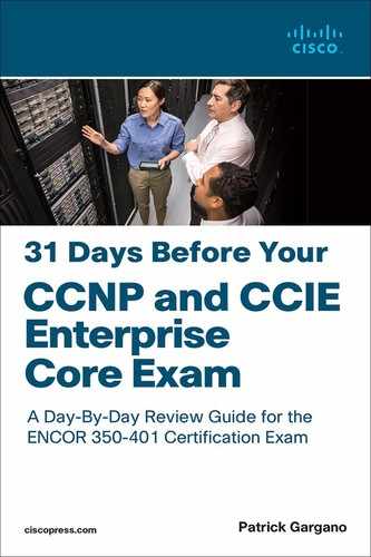
Spanning Tree Protocol provide loop resolution by managing the physical paths to given network segments. STP enables physical path redundancy while preventing the undesirable effects of active loops in the network. STP forces certain ports into a blocking state. These blocking ports do not forward data frames, as illustrated in Figure 28-1.
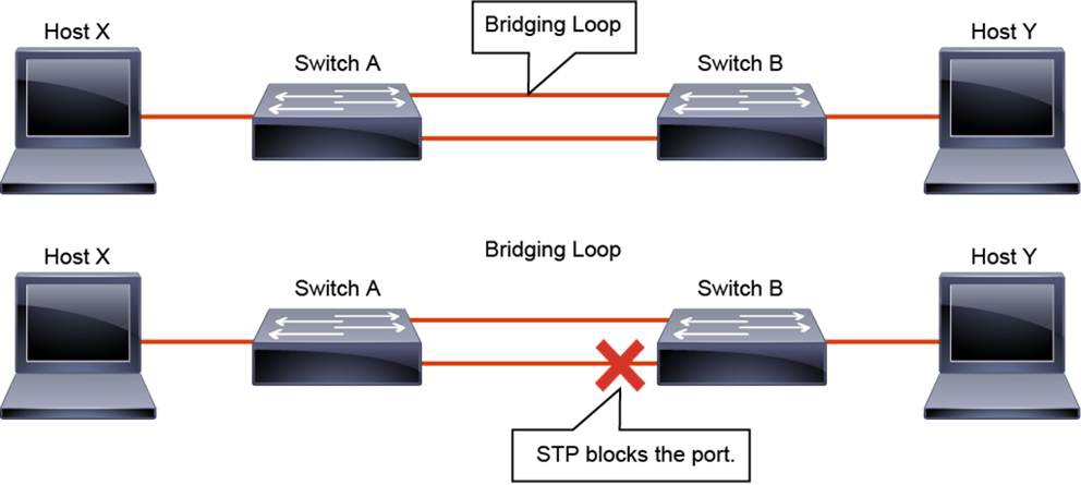
Figure 28-1 Bridging Loop and STP
In a redundant topology, you might see problems such as these:
• Broadcast storms: In a broadcast storm, each switch on a redundant network floods broadcast frames endlessly. Switches flood broadcast frames to all ports except the port on which the frame was received. These frames then travel around the loop in all directions.
• Multiple frame transmission: Multiple copies of the same unicast frames may be delivered to a destination station, which can cause problems with the receiving protocol.
• MAC database instability: This problem results from copies of the same frame being received on different ports of the switch. The MAC address table maps the source MAC address on a received packet to the interface it was received on. If a loop occurs, then the same source MAC address could be seen on multiple interfaces, causing instability.
STP forces certain ports into a standby state so that they do not listen to, forward, or flood data frames. There is only one active path to each network segment. It is a loop-avoidance mechanism that is used to solve problems caused by redundant topology. STP port states are covered later today.
For example, in Figure 28-1, there is a redundant link between Switch A and Switch B. However, this causes a bridging loop. For example, a broadcast or multicast packet that transmits from Host X and is destined for Host Y will continue to loop between these switches. When STP runs on both switches, it blocks one of the ports to prevent the formation of a loop in the network. STP addresses and solves these issues.
To provide this desired path redundancy and to avoid a loop condition, STP defines a tree that spans all the switches in an extended network. STP forces certain redundant data paths into a standby (blocked) state and leaves other paths in a forwarding state. If a link in the forwarding state becomes unavailable, STP reconfigures the network and reroutes data paths through the activation of the appropriate standby path.
STP Operations
STP provides loop resolution by managing the physical path to the given network segment. It does so by performing three steps, as shown in Figure 28-2:
Figure 28-2 STP Operations
1. Elects one root bridge: Only one bridge can act as the root bridge. The root bridge is the reference point, and all data flows in the network are from the perspective of this switch. All ports on a root bridge forward traffic.
2. Selects the root port on each non-root bridge: One port on each non-root bridge is the root port. It is the port with the lowest-cost path from the non-root bridge to the root bridge. By default, the STP path cost is calculated from the bandwidth of the link. You can also set the STP path cost manually.
3. Selects the designated port on each segment: There is one designated port on each segment. It is selected on the bridge with the lowest-cost path to the root bridge and is responsible for forwarding traffic on that segment.
Ports that are neither root nor designated must be non-designated. Non-designated ports are normally in the blocking state to break the loop topology. The overall effect is that only one path to each network segment is active at any time. If there is a problem with connectivity to any of the segments in the network, STP reestablishes connectivity by automatically activating a previously inactive path, if one exists.
Bridge Protocol Data Unit
STP uses bridge protocol data units (BPDUs) to exchange STP information specifically for root bridge election and for loop identification. By default, BPDUs are sent out every 2 seconds. BPDUs are generally categorized into three types:
• Configuration BPDUs: Used to identify the root bridge, root ports, designated ports, and blocking ports.
• TCN (topology change notification) BPDUs: Used when a bridge discovers a change in topology, usually because of a link failure, bridge failure, or port transitioning to the forwarding state. It is forwarded on the root port toward the root bridge.
• TCA (topology change acknowledgment) BPDUs: Used by the upstream bridge to respond to the receipt of a TCN.
Every switch sends out BPDUs on each port. The source address is the MAC address of that port, and the destination address is the STP multicast address 01-80-c2-00-00-00.
In normal STP operation, a switch keeps receiving configuration BPDUs from the root bridge on its root port, but it never sends out a BPDU toward the root bridge. When there is a change in topology, such as a new switch being added or a link going down, the switch sends a TCN BPDU on its root port, as shown in Figure 28-3.

Figure 28-3 BPDU TCN Flow
The designated switch receives the TCN, acknowledges it, and generates another one for its own root port. The process continues until the TCN hits the root bridge. The designated switch acknowledges the TCN by immediately sending back a normal configuration BPDU with the TCA bit set. The switch that notifies the topology change does not stop sending its TCN until the designated switch has acknowledged it. Therefore, the designated switch answers the TCN even though it has not yet received a configuration BPDU from its root.
Once the root is aware that there has been a topology change event in the network, it starts to send out its configuration BPDUs with the topology change (TC) bit set. These BPDUs are relayed by every bridge in the network with this bit set. Bridges receive topology change BPDUs on both forwarding and blocking ports.
There are three types of topology change:
• Direct topology change: This type of change can be detected on an interface. In Figure 28-3, SW4 has detected a link failure on one of its interfaces. It then sends out a TCN message on the root port to reach the root bridge. SW1, the root bridge, announces the topology change to other switches in the network. All switches shorten their bridging table aging time to the forward delay (15 seconds). This way, they get new port and MAC address associations after 15 seconds, not after 300 seconds, which is the default bridging table aging time. The convergence time in that case is two times the forward delay period—that is, 30 seconds.
• Indirect topology change: With this type of change, the link status stays up. Something (for example, another device such as firewall) on the link has failed or is filtering traffic, and no data is received on each side of the link. Because there is no link failure, no TCN messages are sent. The topology change is detected because there are no BPDUs from the root bridge. With an indirect link failure, the topology does not change immediately, but STP converges again, thanks to timer mechanisms. The convergence time in that case is longer than with direct topology change. First, because of the loss of BPDU, the Max Age timer has to expire (20 seconds). Then the port transitions to listening (15 seconds) and then learning (15 seconds), for a total of 50 seconds.
• Insignificant topology change: This type of change occurs if, for example, a PC connected to SW4 is turned off. This event causes SW4 to send out TCNs. However, because none of the switches had to change port states to reach the root bridge, no actual topology change occurred. The only consequence of shutting down the PC is that all switches age out entries from the content-addressable memory (CAM) table sooner than normal. This can become a problem if you have a large number of PCs. Many PCs going up and down can cause a substantial number of TCN exchanges. To avoid this, you can enable PortFast on end-user ports. If a PortFast-enabled port goes up or down, a TCN is not generated.
Root Bridge Election
For all switches in a network to agree on a loop-free topology, a common frame of reference must exist to use as a guide. This reference point is called the root bridge. (The term bridge continues to be used even in a switched environment because STP was developed for use in bridges.) An election process among all connected switches chooses the root bridge. Each switch has a unique bridge ID (BID) that identifies it to other switches. The BID is an 8-byte value consisting of two fields, as shown in Figure 28-4:
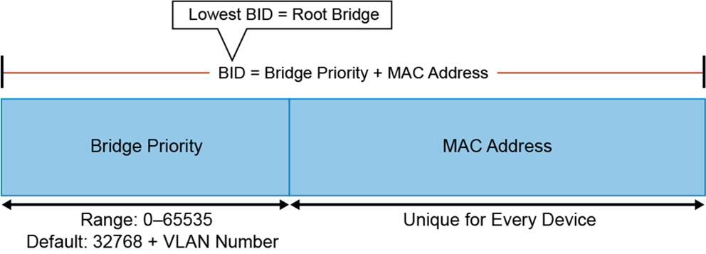
Figure 28-4 STP Bridge ID
• Bridge Priority (2 bytes): The priority or weight of a switch in relationship to all other switches. The Bridge Priority field can have a value of 0 to 65,535, and it defaults to 32,768 (or 0x8000) on every Catalyst switch. In PVST and PVST+ implementations of STP, the original 16-bit Bridge Priority field is split into two fields, resulting in the following components in the BID:
• Bridge Priority: A 4-bit field used to carry bridge priority. The default priority is 32,768, which is the midrange value. The priority is conveyed in discrete values in increments of 4096.
• Extended System ID: A 12-bit field carrying the VLAN ID. This ensures a unique BID for each VLAN configured on the switch.
• MAC Address (6 bytes): The MAC address used by a switch can come from the Supervisor module, the backplane, or a pool of 1024 addresses that are assigned to every supervisor or backplane, depending on the switch model. In any event, this address is hard-coded and unique, and the user cannot change it.
The root bridge is selected based on the lowest BID. If all switches in the network have the same priority, the switch with the lowest MAC address becomes the root bridge.
In the beginning, each switch assumes that it is the root bridge. Each switch sends a BPDU to its neighbors, presenting its BID. At the same time, it receives BPDUs from all its neighbors. Each time a switch receives a BPDU, it checks that BID against its own. If the received bridge ID is better than its own, the switch realizes that it, itself, is not the root bridge. Otherwise, it keeps the assumption of being the root bridge.
Eventually, the process converges, and all switches agree that one of them is the root bridge, as illustrated in Figure 28-5.
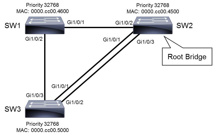
Figure 28-5 STP Root Bridge Election
Root bridge election is an ongoing process. If a new switch appears with a better BID, it is elected the new root bridge. STP includes mechanisms to protect against random or undesirable root bridge changes.
Root Port Election
After the root bridge is elected, each non-root bridge must figure out where it is in relationship to the root bridge. The root port is the port with the best path to the root bridge. To determine root ports on non-root bridges, cost value is used. The path cost is the cumulative cost of all links to the root bridge. The root port has the lowest cost to the root bridge. If two ports have the same cost, the sender’s port ID is used to break the tie.
In Figure 28-6, SW1 has two paths to the root bridge. The root path cost is a cumulative value. The cost of link SW1–SW2 is 4, and the cost of link SW3–SW2 is also 4. The cumulative cost of the path SW1–SW3–SW2 through Gi1/0/2 is 4 + 4 = 8, whereas the cumulative cost of the link SW1–SW2 through Gi1/0/1 is 4. Since the path through GigabitEthernet 1/0/1 has a lower cost, GigabitEthernet 1/0/1 is elected the root port.

Figure 28-6 STP Root Port Election
When two ports have the same cost, arbitration can be done using the advertised port ID (from the neighboring switch). In Figure 28-6, SW3 has three paths to the root bridge. Through Gi1/0/3, the cumulative cost is 8 (links SW3–SW1 and SW1–SW2). Through Gi1/0/1 and Gi1/0/2, the cost is 4. Because lower cost is better, one of these two ports will be elected the root port. Port ID is a combination of a port priority, which is 128 by default, and a port number. For example, in Figure 28-6, the port Gi1/0/1 on SW2 has the port ID 128.1, the port Gi1/0/3 has port ID 128.3. The lowest port ID is always chosen when port ID is the determining factor. Because Gi1/0/1 receives a lower port ID from SW2 (128.1) than Gi1/0/2 receives (128.3), Gi1/0/1 is elected the root port.
STP cost is calculated from the bandwidth of the link. It can be manually changed by the administrator, although such changes are not commonly made.
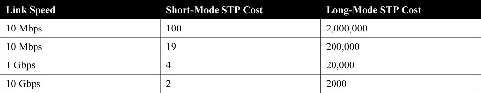
Table 28-1 shows common link cost values. The higher the bandwidth of a link, the lower the cost of transporting data across it. Cisco Catalyst switches support two STP path cost modes: short mode and long mode. Short mode is based on a 16-bit value with a link speed reference value of 20 Gbps, whereas long mode uses a 32-bit value with a link speed reference value of 20 Tbps.
Table 28-1 Default Interface STP Port Costs
Designated Port Election
After the root bridge and root ports on non-root bridges have been elected, STP has to identify which port on the segment should forward the traffic in order to prevent loops from occurring in the network. Only one of the ports on a segment should forward traffic to and from that segment. The designated port—the one forwarding the traffic—is also chosen based on the lowest cost to the root bridge. On the root bridge, all ports are designated.
If there are two paths to the root bridge with equal cost, STP uses the following criteria for best path determination and consequently for determining the designated and non-designated ports on the segment:
• Lowest root path cost to the root bridge
• Lowest sender BID
• Lowest sender port ID
As shown in Figure 28-7, SW2 is the root bridge, so all its ports are designated. To prevent loops, a blocking port for the SW1–SW3 segment has to be determined. Because SW3 and SW1 have the same path cost to the root bridge, 4, the lower BID breaks the tie. SW1 has a lower BID than SW3, so the designated port for the segment is GigabitEthernet1/0/2 on SW1.

Figure 28-7 STP Designated Port Election
Only one port on a segment should forward traffic. All ports that are not root or designated ports are non-designated ports. Non-designated ports go to the blocking state to prevent a loop. Non-designated ports are also referred to as alternate, or backup, ports.
In Figure 28-7, root ports and designated ports are determined on non-root bridges. All the other ports are non-designated. The only two interfaces that are not root or designated ports are GigabitEthernet1/0/2 and GigabitEthernet1/0/3 on SW3. Both are non-designated (blocking).
STP Port States
To participate in the STP process, a switch port must go through several states. A port starts in the disabled state, and then, after an administrator enables it, it moves through various states until it reaches the forwarding state if it is a designated port or a root port. If not, it is moved into the blocking state. Table 28-2 outlines all the STP states and their functionality:
Table 28-2 STP Port States
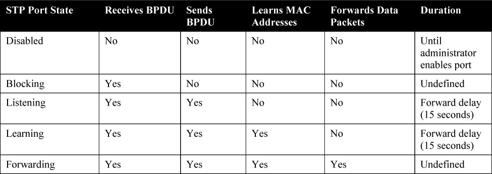
• Blocking: In this state, a port ensures that no bridging loops occur. A port in this state cannot receive or transmit data, but it receives BPDUs, so the switch can hear from its neighbor switches and determine the location and root ID of the root switch and the port role of each switch. A port in this state is a non-designated port, so it does not participate in active topology.
• Listening: A port is moved from the blocking state to the listening state if there is a possibility that it will be selected as the root or designated port. A port in this state cannot send or receive data frames, but it is allowed to send and receive BPDUs, so it participates in the active Layer 2 topology.
• Learning: After the listening state expires (in 15 seconds), the port is moved to the learning state. The port sends and receives BPDUs, and it can also learn and add new MAC addresses to its table. A port in this state cannot send any data frames.
• Forwarding: After the learning state expires (in 15 seconds), the port is moved to the forwarding state if it is to become a root or designated port. It is now considered part of the active Layer 2 topology. It sends and receives frames and sends and receives BPDUs.
• Disabled: In this state, a port is administratively shut down. It does not participate in STP and does not forward frames.
Rapid Spanning Tree Protocol
Rapid Spanning Tree Protocol (RSTP; specified in IEEE 802.1w) significantly speeds the recalculation of the spanning tree when the network topology changes. RSTP defines the additional port roles alternate and backup and defines port states as discarding, learning, or forwarding.
RSTP is an evolution, rather than a revolution, of the 802.1D standard. The 802.1D terminology remains primarily the same, and most parameters are left unchanged. On Cisco Catalyst switches, a rapid version of PVST+, called RPVST+ or PVRST+, is the per-VLAN version of the RSTP implementation. All the current-generation Catalyst switches support Rapid PVST+, and it is now the default version enabled on Catalyst 9000 Series switches.
RSTP Port Roles
The port role defines the ultimate purpose of a switch port and the way it handles data frames. RSTP port roles differ slightly from STP roles. RSTP defines the following port roles (and Figure 28-8 illustrates the port roles in a three-switch topology):
• Root: The root port is the switch port on every non-root bridge that is the chosen path to the root bridge. There can be only one root port on every non-root switch. The root port is considered part of the active Layer 2 topology. It forwards, sends, and receives BPDUs (data messages).
• Designated: Each switch has at least one switch port as the designated port for a segment. In the active Layer 2 topology, the switch with the designated port receives frames on the segment that are destined for the root bridge. There can be only one designated port per segment.
• Alternate: The alternate port is a switch port that offers an alternate path toward the root bridge. It assumes a discarding state in an active topology. The alternate port makes a transition to a designated port if the current designated path fails.
• Disabled: A disabled port has no role in the operation of spanning tree.
• Backup: The backup port is an additional switch port on the designated switch with a redundant link to a shared segment for which the switch is designated. The backup port has the discarding state in the active topology.

Figure 28-8 RSTP Port Roles
Notice that instead of the STP non-designated port role, there are now alternate and backup ports. These additional port roles allow RSTP to define a standby switch port before a failure or topology change. The alternate port moves to the forwarding state if there is a failure on the designated port for the segment. A backup port is used only when a switch is connected to a shared segment using a hub, as illustrated in Figure 28-8.
RSTP Port States
The RSTP port states correspond to the three basic operations of a switch port: discarding, learning, and forwarding. There is no listening state with RSTP, as there is with STP. With RSTP, the listening and blocking STP states are replaced with the discarding state. In a stable topology, RSTP ensures that every root port and designated port transit to the forwarding state, and all alternate ports and backup ports are always in the discarding state. Table 28-3 depicts the characteristics of RSTP port states.
Table 28-3 RSTP Port States

A port accepts and processes BPDU frames in all port states.
RSTP Rapid Transition to Forwarding State
A quick transition to the forwarding state is a key feature of 802.1w. The legacy STP algorithm passively waited for the network to converge before it turned a port into the forwarding state. To achieve faster convergence, a network administrator had to manually tune the conservative default parameters (Forward Delay and Max Age timers). This often put the stability of the network at stake. RSTP is able to quickly confirm that a port can safely transition to the forwarding state without having to rely on any manual timer configuration. In order to achieve fast convergence on a port, the protocol relies on two new variables: edge ports and link type.
Edge Ports
The edge port concept is already well known to Cisco STP users, as it basically corresponds to the PortFast feature. Ports that are directly connected to end stations cannot create bridging loops in the network. An edge port directly transitions to the forwarding state and skips the listening and learning stages. Neither edge ports nor PortFast-enabled ports generate topology changes when the link toggles. An edge port that receives a BPDU immediately loses edge port status and becomes a normal STP port. Cisco maintains that the PortFast feature can be used for edge port configuration in RSTP.
Link Type
RSTP can achieve rapid transition to the forwarding state only on edge ports and on point-to-point links. The link type is automatically derived from the duplex mode of a port. A port that operates in full-duplex is assumed to be point-to-point, while a half-duplex port is considered to be a shared port by default. This automatic link type setting can be overridden with explicit configuration. In switched networks today, most links operate in full-duplex mode and are treated as point-to-point links by RSTP. This makes them candidates for rapid transition to the forwarding state.
RSTP Synchronization
To participate in RSTP convergence, a switch must decide the state of each of its ports. Non-edge ports begin in the discarding state. After BPDUs are exchanged between the switch and its neighbor, the root bridge can be identified. If a port receives a superior BPDU from a neighbor, that port becomes the root port.
For each non-edge port, the switch exchanges a proposal-agreement handshake to decide the state of each end of the link. Each switch assumes that its port should become the designated port for the segment, and a proposal message (a configuration BPDU) is sent to the neighbor to suggest this.
When a switch receives a proposal message on a port, the following sequence of events occurs (and Figure 28-9 shows the sequence, based on the center switch):
1. If the proposal’s sender has a superior BPDU, the local switch realizes that the sender should be the designated switch (having the designated port) and that its own port must become the new root port.
2. Before the switch agrees to anything, it must synchronize itself with the topology.
3. All non-edge ports immediately are moved into the discarding (blocking) state so that no bridging loops can form.
4. An agreement message (a configuration BPDU) is sent back to the sender, indicating that the switch agrees with the new designated port choice. This also tells the sender that the switch is in the process of synchronizing itself.
5. The root port immediately is moved to the forwarding state. The sender’s port also immediately can begin forwarding.
6. For each non-edge port that is currently in the discarding state, a proposal message is sent to the respective neighbor.
7. An agreement message is expected and received from a neighbor on a non-edge port.
8. The non-edge port is immediately moved to the forwarding state.
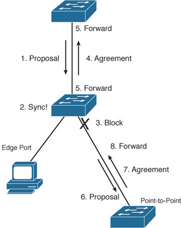
Figure 28-9 RSTP Convergence
Notice that the RSTP convergence begins with a switch sending a proposal message. The recipient of the proposal must synchronize itself by effectively isolating itself from the rest of the topology. All non-edge ports are blocked until a proposal message can be sent, causing the nearest neighbors to synchronize themselves. This creates a moving “wave” of synchronizing switches, which can quickly decide to start forwarding on their links only if their neighbors agree.
RSTP Topology Change
For RSTP, a topology change occurs only when a non-edge port transitions to the forwarding state. This means a loss of connectivity is not considered a topology change, as it is with STP. A switch announces a topology change by sending out BPDUs with the TC bit set from all the non-edge designated ports. This way, all the neighbors are informed about the topology change, and they can correct their bridging tables. In Figure 28-10, SW4 sends BPDUs out all its non-edge ports after it detects a link failure. SW2 then sends the BPDU to all its neighbors except for the one that received the BPDU from SW4, and so on.
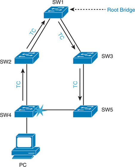
Figure 28-10 RSTP Topology Change
When a switch receives a BPDU with TC bit set from a neighbor, it clears the MAC addresses learned on all its ports except the one that receives the topology change. The switch also receives BPDUs with the TC bit set on all designated ports and the root port. RSTP no longer uses the specific TCN BPDUs unless a legacy bridge needs to be notified. With RSTP, the TC propagation is a one-step process. In fact, the initiator of the topology change floods this information throughout the network, whereas with 802.1D, only the root does. This mechanism is much faster than the 802.1D equivalent.
STP and RSTP Configuration and Verification
Using the topology shown in Figure 28-11, this section reviews how to manually configure a root bridge and the path for spanning tree. In the topology, all switches are initially configured with PVST+ and are in VLAN 1. This configuration example also allows you to verify STP and RSTP functionality.
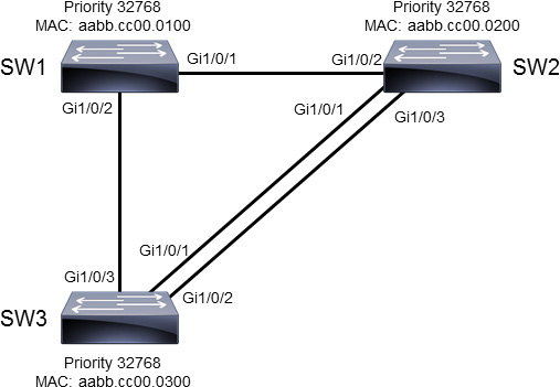
Figure 28-11 STP/RSTP Configuration Example Topology
There are two loops in this topology: SW1–SW2–SW3 and SW2–SW3. Wiring the network in this way provides redundancy, but Layer 2 loops occur if STP does not block redundant links. By default, STP is enabled on all the Cisco switches for VLAN 1. To find out which switch is the root switch and discover the STP port role for each switch, use the show spanning-tree command, as shown in Example 28-1.
Example 28-1 Verifying the STP Bridge ID
SW1# show spanning-tree

VLAN0001
  Spanning tree enabled protocol ieee
  Root ID    Priority    32769
             Address     aabb.cc00.0100
             This bridge is the root
             Hello Time   2 sec  Max Age 20 sec  Forward Delay 15 sec

  Bridge ID  Priority    32769  (priority 32768 sys-id-ext 1)
             Address     aabb.cc00.0100
<... output omitted ...>
SW2# show spanning-tree

VLAN0001
  Spanning tree enabled protocol ieee
  Root ID    Priority    32769
             Address     aabb.cc00.0100
             Cost        100
             Port        3 (GigabitEthernet1/0/2)
             Hello Time   2 sec  Max Age 20 sec  Forward Delay 15 sec

  Bridge ID  Priority    32769  (priority 32768 sys-id-ext 1)
             Address     aabb.cc00.0200
<... output omitted ...>
SW3# show spanning-tree

VLAN0001
  Spanning tree enabled protocol ieee
  Root ID    Priority    32769
             Address     aabb.cc00.0100
             Cost        100
             Port        4 (GigabitEthernet1/0/3)
             Hello Time   2 sec  Max Age 20 sec  Forward Delay 15 sec

  Bridge ID  Priority    32769  (priority 32768 sys-id-ext 1)
             Address     aabb.cc00.0300
<... output omitted ...>
SW1 is the root bridge. Because all three switches have the same bridge priority (32769), the switch with the lowest MAC address is elected as the root bridge. Recall that the default bridge priority is 32768, but the extended system ID value for VLAN 1 is added, giving us 32769.
The first line of output for each switch confirms that the active spanning tree protocol is the IEEE-based PVST+.
Using the show spanning-tree command allows you to investigate the port roles on all three switches, as shown in Example 28-2.
Example 28-2 Verifying the STP Port Roles
SW1# show spanning-tree
<... output omitted ...>
Interface           Role Sts Cost      Prio.Nbr Type
------------------- ---- --- --------- -------- --------------------------------
Gi1/0/1             Desg FWD 4         128.1    P2p
Gi1/0/2             Desg FWD 4         128.2    P2p
SW2# show spanning-tree
<... output omitted ...>
Interface           Role Sts Cost      Prio.Nbr Type
------------------- ---- --- --------- -------- --------------------------------
Gi1/0/1             Desg FWD 4         128.1    P2p
Gi1/0/2             Root FWD 4         128.2    P2p
Gi1/0/3             Desg FWD 4         128.3    P2p
SW3# show spanning-tree
<... output omitted ...>
Interface           Role Sts Cost      Prio.Nbr Type
------------------- ---- --- --------- -------- --------------------------------
Gi1/0/1             Altn BLK 4         128.1    P2p
Gi1/0/2             Altn BLK 4         128.2    P2p
Gi1/0/3             Root FWD 4         128.3    P2p
Because SW1 is the root bridge, it has both of its connected ports in the designated (forwarding) state.
Because SW2 and SW3 are not the root bridge, only one port must be elected root on each of these two switches. The root port is the port with the lowest cost to the root bridge. As SW2 has a lower BID than SW3, all ports on SW2 are set to designated. Other ports on SW3 are non-designated. The Cisco-proprietary protocol PVST+ uses the term "alternate" for non-designated ports. Figure 28-12 shows the summary of the spanning-tree topology and the STP port states for the three-switch topology.

Figure 28-12 STP Port Roles and States
Changing STP Bridge Priority
It is not advisable for a network to choose the root bridge by itself. If all switches have default STP priorities, the switch with the lowest MAC address becomes the root bridge. The oldest switch has the lowest MAC address because the lower MAC addresses were factory assigned first. To manually set the root bridge, you can change a switch’s bridge priority. In Figure 28-12, assume that the access layer switch SW3 becomes the root bridge because it has the oldest MAC address. If SW3 is the root bridge, the link between the distribution layer switches is blocked. The traffic between SW1 and SW2 then needs to go through SW3, which is not optimal.
The priority can be a value between 0 and 65,535, in increments of 4096.
A better solution is to use the spanning-tree vlan vlan-id root {primary | secondary} command. This command is actually a macro that lowers the switch’s priority number so that it becomes the root bridge.
To configure the switch to become the root bridge for a specified VLAN, use the primary keyword. Use the secondary keyword to configure a secondary root bridge. This prevents the slowest and oldest access layer switch from becoming the root bridge if the primary root bridge fails.
The spanning-tree root command calculates the priority by learning the current root priority and lowering its priority by 4096. For example, if the current root priority is more than 24,576, the local switch sets its priority to 24,576. If the root bridge has priority lower than 24,576, the local switch sets its priority to 4096 less than the priority of the current root bridge. Configuring the secondary root bridge sets a priority of 28,672. There is no way for the switch to figure out what is the second-best priority in the network. So, setting the secondary priority to 28,672 is just a best guess. It is also possible to manually enter a priority value by using the spanning-tree vlan vlan-id priority bridge-priority configuration command.
If you issue the show running-configuration command, the output shows the switch’s priority as a number (not the primary or secondary keyword).
Example 28-3 shows the command to make SW2 the root bridge and the output from the show spanning-tree command to verify the result.
Example 28-3 Configuring STP Root Bridge Priority
SW2(config)# spanning-tree vlan 1 root primary

SW2# show spanning-tree

VLAN0001
  Spanning tree enabled protocol ieee
  Root ID    Priority    24577
             Address     aabb.cc00.0200
             This bridge is the root
             Hello Time   2 sec  Max Age 20 sec  Forward Delay 15 sec

  Bridge ID  Priority    28673  (priority 28672 sys-id-ext 1)
             Address     aabb.cc00.0200
             Hello Time   2 sec  Max Age 20 sec  Forward Delay 15 sec
             Aging Time  15  sec

Interface           Role Sts Cost      Prio.Nbr Type
------------------- ---- --- --------- -------- --------------------------------
Gi1/0/1             Desg FWD 4         128.1    P2p
Gi1/0/2             Desg FWD 4         128.2    P2p
Gi1/0/3             Desg FWD 4         128.3    P2p
SW1# show spanning-tree
<... output omitted ...>
Interface           Role Sts Cost      Prio.Nbr Type
------------------- ---- --- --------- -------- --------------------------------
Gi1/0/1             Root FWD 4         128.1    P2p
Gi1/0/2             Desg FWD 4         128.2    P2p
SW3# show spanning-tree
<... output omitted ...>
Interface           Role Sts Cost      Prio.Nbr Type
------------------- ---- --- --------- -------- --------------------------------
Gi1/0/1             Root FWD 4         128.1    P2p
Gi1/0/2             Altn BLK 4         128.2    P2p
Gi1/0/3             Altn BLK 4         128.3    P2p
Since SW2 is the root bridge, all its ports are in the designated state, or forwarding. SW1 and SW3 have changed port roles according to the change of the root bridge.
Figure 28-13 shows the port roles before and after you configure SW2 as the root bridge.
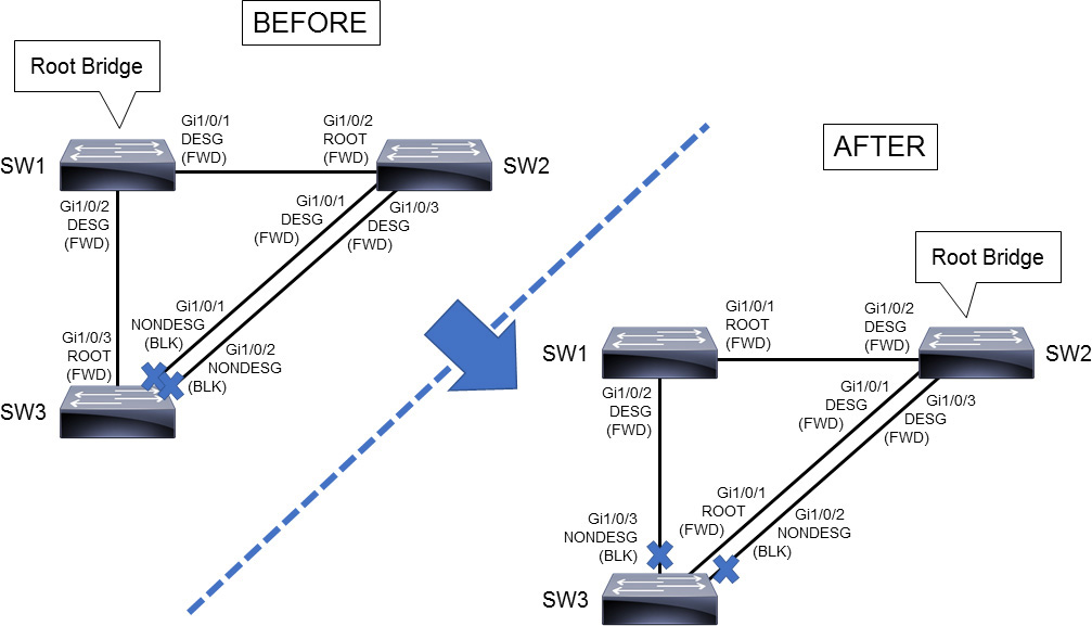
Figure 28-13 Root Bridge Change from SW1 to SW2
STP Path Manipulation
For port role determination, the cost value is used. If all ports have the same cost, the sender’s port ID breaks the tie. To control active port selection, change the cost of the interface or the sender’s interface port ID.
You can modify port cost by using the spanning-tree vlan vlan-id cost cost-value command. The cost value can be between 1 and 65,535.
The port ID consists of a port priority and a port number. The port number is fixed because it is based only on its hardware location, but you can influence the port ID by configuring the port priority.
You modify the port priority by using the spanning-tree vlan vlan-id port-priority port-priority command. The value of port priority can be between 0 and 255; the default is 128. A lower port priority means a more preferred path to the root bridge.
As shown in Figure 28-14, GigabitEthernet1/0/1 and GigabitEthernet1/0/2 of SW3 have the same interface STP cost to the root SW2. GigabitEthernet1/0/1 of SW3 is forwarding because its sender’s port ID of GigabitEthernet1/0/1 of SW2 (128.1) is lower than that of its GigabitEthernet1/0/3 (128.3) of SW2. One way that you could transition SW3’s GigabitEthernet1/0/2 to the forwarding port state is to lower the port cost on GigabitEthernet1/0/2. Another way to transition SW3’s GigabitEthernet1/0/2 port state to forwarding is to lower the sender’s port priority. In this case, this is GigabitEthernet1/0/3 on SW2.

Figure 28-14 STP Path Manipulation
Example 28-4 shows that by changing the cost of SW3’s GigabitEthernet1/0/2 interface, the sender interface port priority is no longer observed. STP checks port priority only when costs are equal. Figure 28-15 shows the topology before and after manipulation of the STP port cost.
Example 28-4 Configuration to Change the STP Port Cost
SW3(config)# interface GigabitEthernet 1/0/2
SW3(config-if)# spanning-tree vlan 1 cost 3
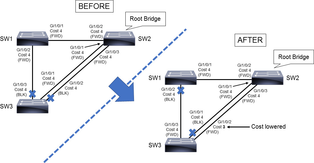
Figure 28-15 STP Interface Cost Manipulation
You can investigate the STP port roles on SW1 and SW3 by using the show spanning-tree command, as shown in Example 28-5. Here you can see that interface GigabitEthernet1/0/2 now has a lower cost, and it is assigned as the root port (unlike in its original state). STP reconsiders the new lower-cost path between S3 and S2, and new port roles are assigned on SW1 and SW3. Because SW2 is the root bridge, it has all ports as designated (forwarding). Because SW3 has a lower-cost path to the root bridge (SW2), SW3 becomes the designated bridge for the link between SW1 and SW3.
Example 28-5 Verifying STP Port Cost and Port State
SW1# show spanning-tree
<... output omitted ...>
Interface           Role Sts Cost      Prio.Nbr Type
------------------- ---- --- --------- -------- --------------------------------
Gi1/0/1             Root FWD 4         128.1    P2p
Gi1/0/2             Altn BLK 4         128.2    P2p

SW3# show spanning-tree
<... output omitted ...>
Interface           Role Sts Cost      Prio.Nbr Type
------------------- ---- --- --------- -------- --------------------------------
Gi1/0/1             Altn BLK 4         128.2    P2p
Gi1/0/2             Root FWD 3         128.3    P2p
Gi1/0/3             Desg FWD 4         128.4    P2p
Enabling and Verifying RSTP
You can use the spanning-tree mode rapid-pvst global configuration command to enable the Cisco Rapid-PVST+ version of STP on all switches. Use the show spanning-tree command to verify that RSTP is successfully enabled, as shown in Example 28-6. If all but one switch in the network is running RSTP, the interfaces that lead to legacy STP switches automatically fall back to PVST+. Port roles, port status, cost, and port ID remain as they were in Figure 28-15, but the network converges more quickly when RSTP is enabled.
Example 28-6 Configuring RSTP and Verifying STP Mode
SW1(config)# spanning-tree mode rapid-pvst

SW2(config)# spanning-tree mode rapid-pvst

SW3(config)# spanning-tree mode rapid-pvst
SW1# show spanning-tree

VLAN0001
  Spanning tree enabled protocol rstp
  <... output omitted ...>

SW2# show spanning-tree

VLAN0001
  Spanning tree enabled protocol rstp
  <... output omitted ...>

SW3# show spanning-tree

VLAN0001
  Spanning tree enabled protocol rstp
  <... output omitted ...>
STP Stability Mechanisms
Achieving and maintaining a loop-free STP topology revolves around the simple process of sending and receiving BPDUs. Under normal conditions, the loop-free topology is determined dynamically. This section reviews the STP features that can protect a network against unexpected BPDUs being received or the sudden loss of BPDUs. This section focuses on the following mechanisms:
• STP PortFast and BPDU Guard
• Root Guard
• Loop Guard
• Unidirectional Link Detection
STP PortFast and BPDU Guard
As previously discussed, if a switch port connects to another switch, the STP initialization cycle must transition from state to state to ensure a loop-free topology. However, for access devices such as PCs, laptops, servers, and printers, the delays that are incurred with STP initialization can cause problems such as DHCP timeouts. Cisco designed PortFast to reduce the time required for an access device to enter the forwarding state. STP is designed to prevent loops. Because there can be no loop on a port that is connected directly to a host or server, the full function of STP is not needed for that port. PortFast is a Cisco enhancement to STP that allows a switch port to begin forwarding much faster than a switch port in normal STP mode.
In a valid PortFast configuration, configuration BPDUs should never be received because access devices do not generate BPDUs. A BPDU that a port receives would indicate that another bridge or switch is connected to the port. This event could happen if a user plugged a switch on their desk into the port where the user PC was already plugged in.
The STP PortFast BPDU Guard enhancement allows network designers to enforce the STP domain borders and keep the active topology predictable. The devices behind the ports that have STP PortFast enabled are not able to influence the STP topology. At the reception of BPDUs, the BPDU Guard operation disables the port that has PortFast configured. The BPDU Guard mechanism transitions the port into errdisable state, and a message appears at the console. For example, the following message might appear:
%SPANTREE-2-BLOCK_BPDUGUARD: Received BPDU on port GigabitEthernet1/0/8 with BPDU guard
enabled. Disabling port.
%PM-4-ERR_DISABLE: bpduguard error detected on Gi1/0/8, putting Gi1/0/8 in err-disable state
Note
Because the purpose of PortFast is to minimize the time that access ports that are connecting to user equipment and servers must wait for spanning tree to converge, you should use it only on access ports. If you enable PortFast on a port that is connecting to another switch, you risk creating a spanning-tree loop. Keep in mind that the BPDU Filter feature is available but not recommended. You should enable BPDU Guard on all PortFast-enabled ports to prevent a switch from being connected to a switch port that is dedicated for an end device.
The spanning-tree bpduguard enable interface configuration command configures BPDU Guard on an interface. The spanning-tree portfast bpduguard default global configuration command enables BPDU Guard globally for all PortFast-enabled ports.
The spanning-tree portfast interface configuration command configures PortFast on an interface. The spanning-tree portfast default global configuration command enables PortFast on all nontrunking interfaces.
Example 28-7 shows how to configure and verify PortFast and BPDU Guard on an interface on SW1 and globally on SW2
Example 28-7 Configuring and Verifying PortFast and BPDU Guard
SW1(config)# interface GigabitEthernet 1/0/8
SW1(config-if)# spanning-tree portfast
SW1(config-if)# spanning-tree bpduguard enable

SW2(config)# spanning-tree portfast default
SW2(config)# spanning-tree portfast bpduguard default


SW1# show running-config interface GigabitEthernet1/0/8
<... output omitted ...>
interface GigabitEthernet1/0/8
<... output omitted ...>
spanning-tree portfast
spanning-tree bpduguard enable
end

SW2# show spanning-tree summary
<... output omitted ...>
Portfast Default             is enabled
PortFast BPDU Guard Default  is enabled
<... output omitted ...>

SW1# show spanning-tree interface GigabitEthernet1/0/8 portfast
VLAN0010            enabled
Note that the syntax for enabling PortFast can vary between switch models and IOS versions. For example, NX-OS uses the spanning-tree port type edge command to enable the PortFast feature. Since Cisco IOS Release 15.2(4)E or IOS XE 3.8.0E, if you enter the spanning-tree portfast command in the global or interface configuration mode, the system automatically saves it as spanning-tree portfast edge.
Root Guard
The Root Guard feature was developed to control where candidate root bridges can be connected and found on a network. Once a switch learns the current root bridge’s bridge ID, if another switch advertises a superior BPDU, or one with a better bridge ID, on a port where Root Guard is enabled, the local switch does not allow the new switch to become the root. As long as the superior BPDUs are being received on the port, the port is kept in the root-inconsistent STP state. No data can be sent or received in that state, but the switch can listen to BPDUs received on the port to detect a new root advertising itself.
Use Root Guard on switch ports where you never expect to find the root bridge for a VLAN. When a superior BPDU is heard on the port, the entire port, in effect, becomes blocked.
In Figure 28-16, switches DSW1 and DSW2 are the core of the network. DSW1 is the root bridge for VLAN 1. ASW is an access layer switch. The link between DSW2 and ASW is blocking on the ASW side. ASW should never become the root bridge, so Root Guard is configured on DSW1 GigabitEthernet 1/0/2 and DSW2 GigabitEthernet 1/0/1. Example 28-8 shows the configuration of the Root Guard feature for the topology in Figure 28-16.
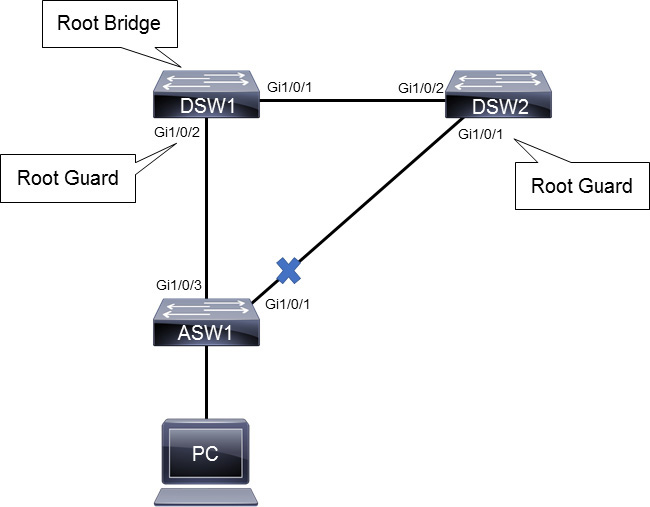
Figure 28-16 Root Guard Topology Example
Example 28-8 Configuring Root Guard
DSW1(config)# interface GigabitEthernet 1/0/2
DSW1(config-if)# spanning-tree guard root
%SPANTREE-2-ROOTGUARD_CONFIG_CHANGE: Root guard enabled on port GigabitEthernet1/0/2.

DSW2(config)# interface GigabitEthernet 1/0/1
DSW2(config-if)# spanning-tree guard root
%SPANTREE-2-ROOTGUARD_CONFIG_CHANGE: Root guard enabled on port GigabitEthernet1/0/1.
If a superior BPDU is received on a Root Guard port, the following message is sent to the console:
%SPANTREE-2-ROOTGUARD_BLOCK: Root guard blocking port GigabitEthernet1/0/2 on VLAN0001.
STP Loop Guard
The STP Loop Guard feature provides additional protection against Layer 2 loops. A Layer 2 loop is created when an STP blocking port in a redundant topology erroneously transitions to the forwarding state. This usually happens because one of the ports of a physically redundant topology (not necessarily the STP blocking port) no longer receives STP BPDUs. In its operation, STP relies on continuous reception or transmission of BPDUs based on the port role. The designated port transmits BPDUs, and the non-designated port receives BPDUs.
When one of the ports in a physically redundant topology no longer receives BPDUs, STP conceives that the topology is loop free. Eventually, the blocking port from the alternate or backup port becomes designated and moves to a forwarding state. This situation creates a loop, as shown in Figure 28-17.
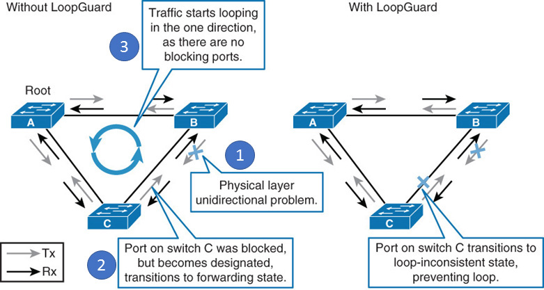
Figure 28-17 Loop Guard Example
The Loop Guard feature makes additional checks. If BPDUs are not received on a non-designated port, and Loop Guard is enabled, that port is moved into the STP loop-inconsistent blocking state instead of the listening/learning/forwarding state.
Once the BPDU is received on a port in a loop-inconsistent STP state, the port transitions into another STP state. According to the received BPDU, this means that the recovery is automatic, and intervention is not necessary.
Example 28-9 shows the configuration and verification of Loop Guard on switches SW1 and SW2. Notice that Loop Guard is configured at the interface level on SW1 and globally on SW2.
Example 28-9 Configuring and Verifying Loop Guard
SW1(config)# interface GigabitEthernet1/0/1
SW1(config-if)# spanning-tree guard loop

SW2(config)# spanning-tree loopguard default
SW1# show spanning-tree interface GigabitEthernet 1/0/1 detail
<...output omitted...>
   Loop guard is enabled on the port
   BPDU: send 6732, received 2846

SW2# show spanning-tree summary
Switch is in rapid-pvst mode
Root bridge for: none
Extended system ID              is enabled
Portfast Default                is disabled
PortFast BPDU Guard Default     is disabled
Portfast BPDU Filter Default    is disabled
Loopguard Default               is enabled
EtherChannel misconfig guard    is enabled
<...output omitted...>
Unidirectional Link Detection
Unidirectional Link Detection (UDLD) is a Cisco-proprietary protocol that detects unidirectional links and prevents Layer 2 loops from occurring across fiber-optic cables. UDLD is a Layer 2 protocol that works with the Layer 1 mechanisms to determine the physical status of a link. If one fiber strand in a pair is disconnected, autonegotiation prevents the link from becoming active or staying up. If both fiber strands are functional from a Layer 1 perspective, UDLD determines whether traffic is flowing bidirectionally between the correct neighbors.
The switch periodically transmits UDLD packets on an interface with UDLD enabled. If the packets are not echoed back within a specific time frame, the link is flagged as unidirectional, and the interface is error disabled. Devices on both ends of the link must support UDLD for the protocol to successfully identify and disable unidirectional links.
After UDLD detects a unidirectional link, it can take two courses of action, depending on the configured mode:
• Normal mode: In this mode, when a unidirectional link is detected, the port is allowed to continue its operation. UDLD just marks the port as having an undetermined state. A syslog message is generated.
• Aggressive mode: In this mode, when a unidirectional link is detected, the switch tries to reestablish the link. It sends one message per second, for 8 seconds. If none of these messages are sent back, the port is placed in an error-disabled state.
You configure UDLD on a per-port basis, although you can enable it globally for all fiber-optic switch ports (either native fiber or fiber-based GBIC or SFP modules). By default, UDLD is disabled on all switch ports. To enable it globally, use the global configuration command udld {enable | aggressive | message time seconds}.
For normal mode, use the enable keyword; for aggressive mode, use the aggressive keyword. You can use the message time keywords to set the message interval, in seconds, ranging from 1 to 90 seconds. The default interval is 15 seconds.
You also can enable or disable UDLD on individual switch ports, if needed, by using the interface configuration command udld {enable | aggressive | disable}.
You can use the disable keyword to completely disable UDLD on a fiber-optic interface.
Example 28-10 shows the configuration and verification of UDLD on SW1. Assume that UDLD is also enabled on its neighbor SW2.
Example 28-10 Configuring and Verifying UDLD
SW1(config)# udld aggressive

SW1# show udld GigabitEthernet2/0/1
Interface Gi2/0/1
---
Port enable administrative configuration setting: Enabled / in aggressive mode
Port enable operational state: Enabled / in aggressive mode
Current bidirectional state: Bidirectional
Current operational state: Advertisement - Single Neighbor detected
Message interval: 15000 ms
Time out interval: 5000 ms

<...output omitted...>

    Entry 1
    ---
    Expiration time: 37500 ms
    Cache Device Index: 1
    Current neighbor state: Bidirectional
    Device ID: 94DE32491I
    Port ID: Gi2/0/1
    Neighbor echo 1 device: 9M34622MQ2
    Neighbor echo 1 port: Gi2/0/1

    TLV Message interval: 15 sec
       No TLV fast-hello interval
    TLV Time our interval: 5
    TLV CDP Device name: SW2

SW1# show udld neighbors
Port     Device Name          Device ID  Port ID  Neighbor State
-------- -------------------- ---------- -------- --------------
Gi2/0/1  SW1                  1          Gi2/0/1  Bidirectional
Multiple Spanning Tree Protocol
The main purpose of Multiple Spanning Tree Protocol (MST) is to reduce the total number of spanning-tree instances to match the physical topology of the network. Reducing the total number of spanning-tree instances reduces the CPU loading of a switch. The number of instances of spanning tree is reduced to the number of links (that is, active paths) that are available.
In a scenario where PVST+ is implemented, there could be up to 4094 instances of spanning tree, each with its own BPDU conversations, root bridge elections, and path selections.
Figure 28-18 illustrates an example where the goal would be to achieve load distribution with VLANs 1 through 500 using one path and VLANs 501 through 1000 using the other path. Instead of creating 1000 PVST+ instances, you can use MST with only two instances of spanning tree. The two ranges of VLANs are mapped to two MST instances, respectively. Rather than maintain 1000 spanning trees, each switch needs to maintain only two.

Figure 28-18 VLAN Load Balancing Example
Implemented in this fashion, MST converges faster than PVST+ and is backward compatible with 802.1D STP, 802.1w RSTP, and the Cisco PVST+ architecture. Implementation of MST is not required if the Cisco enterprise campus architecture is being employed because the number of active VLAN instances, and hence the number of STP instances, would be small and very stable due to the design.
MST allows you to build multiple spanning trees over trunks by grouping VLANs and associating them with spanning-tree instances. Each instance can have a topology independent of other spanning-tree instances. This architecture provides multiple active forwarding paths for data traffic and enables load balancing.
With MST, network fault tolerance is improved over CST (Common Spanning Tree) because a failure in one instance (forwarding path) does not necessarily affect other instances. The VLAN-to-MST grouping must be consistent across all bridges within an MST region. Interconnected bridges that have the same MST configuration are referred to as an MST region.
You must configure a set of bridges with the same MST configuration information to enable them to participate in a specific set of spanning-tree instances. Bridges with different MST configurations or legacy bridges running 802.1D are considered separate MST regions. MST is defined in the IEEE 802.1s standard and has been part of the 802.1Q standard since 2005.
MST Regions
MST differs from the other spanning tree implementations in that it combines some, but not necessarily all, VLANs into logical spanning-tree instances. With MST, there is a problem of determining which VLAN is to be associated with which instance. More precisely, this issue means tagging BPDUs so that receiving devices can identify the instances and the VLANs to which they apply.
The issue is irrelevant in the case of the 802.1D standard, in which all instances are mapped to a unique CST instance. In the PVST+ implementation, different VLANs carry the BPDUs for their respective instances (one BPDU per VLAN), based on the VLAN tagging information. To provide this logical assignment of VLANs to spanning trees, each switch that is running MST in the network has a single MST configuration consisting of three attributes:
• An alphanumeric configuration name (32 bytes)
• A configuration revision number (2 bytes)
• A table that associates each potential VLAN supported on the chassis with a given instance
To ensure a consistent VLAN-to-instance mapping, it is necessary for the protocol to be able to identify the boundaries of the regions exactly. For that purpose, the characteristics of the region are included in BPDUs. The exact VLAN-to-instance mapping is not propagated in the BPDU because the switches need to know only whether they are in the same region as a neighbor.
Therefore, only a digest of the VLAN-to-instance-mapping table is sent, along with the revision number and the name. After a switch receives a BPDU, it extracts the digest (a numeric value that is derived from the VLAN-to-instance-mapping table through a mathematical function) and compares it with its own computed digest. If the digests differ, the mapping must be different, so the port on which the BPDU was received is at the boundary of a region.
In generic terms, a port is at the boundary of a region if the designated bridge on its segment is in a different region or if it receives legacy 802.1D BPDUs. Figure 28-19 illustrates the concept of MST regions and boundary ports.
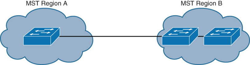
Figure 28-19 MST Regions
The configuration revision number gives you a method of tracking the changes that are made to an MST region. This number does not automatically increase each time that you make changes to the MST configuration. Each time you make a change, you should increase the revision number by one.
MST Instances
MST was designed to interoperate with all other forms of STP. Therefore, it also must support STP instances from each STP type. This is where MST can get confusing. Think of the entire enterprise network as having a single CST topology so that one instance of STP represents any and all VLANs and MST regions present. CST maintains a common loop-free topology and integrates all forms of STP that might be in use. To do this, CST must regard each MST region as a single “black box” bridge because it has no idea what is inside the region (and it does not care). CST maintains a loop-free topology only with the links that connect the regions to each other and to standalone switches running 802.1Q CST.
Something other than CST must work out a loop-free topology inside each MST region. Within a single MST region, an Internal Spanning Tree (IST) instance runs to work out a loop-free topology between the links where CST meets the region boundary and all switches inside the region. Think of the IST instance as a locally significant CST, bounded by the edges of the region.
IST presents the entire region as a single virtual bridge to CST outside. BPDUs are exchanged at the region boundary only over the native VLAN of trunks.
Figure 28-20 shows the basic concept behind the IST instance. The network at the left has an MST region, where several switches are running compatible MST configurations. Another switch is outside the region because it is running only CST from 802.1Q.

Figure 28-20 MST, IST, and CST Example
The same network is shown at the right, where IST has produced a loop-free topology for the network inside the region. IST makes the internal network looks like a single bridge (the “big switch” in the cloud) that can interface with CST running outside the region.
Recall that the whole idea behind MST is the capability to map multiple VLANs to a smaller number of STP instances. Inside a region, the actual MST instances (MSTI) exist alongside IST. Cisco supports a maximum of 16 MST instances in each region. IST always exists as MST instance number 0, leaving MST instances 1 through 15 available for use.
Figure 28-21 shows how different MST instances can exist within a single MST region. The left portion of the figure is identical to that of Figure 28-20. In this network, two MST instances, MSTI 1 and MSTI 2, are configured with different VLANs mapped to each. Their topologies follow the same structure as the network on the left side of the figure, but they have converged differently.
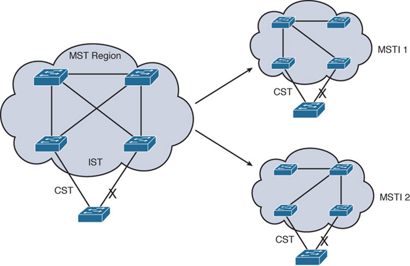
Figure 28-21 MST Instances
MST Configuration and Verification
The left side of Figure 28-22 shows an initial STP configuration. All three switches are configured with Rapid PVST+ and four user-created VLANs: 2, 3, 4, and 5. SW1 is configured as the root bridge for VLANs 2 and 3. SW2 is configured as the root bridge for VLANs 4 and 5. This configuration distributes forwarding of traffic between the SW3–SW1 and SW3–SW2 uplinks.

Figure 28-22 MST Configuration Topology
The right side of Figure 28-22 shows the STP configuration after VLANs 2 and 3 are mapped into MST Instance 1 and VLANs 4 and 5 are mapped into MST Instance 2.
Example 28-11 shows the commands to configure and verify MST on all three switches in order to achieve the desired load balancing shown in Figure 28-22.
Example 28-11 Configuring MST
SW1(config)# spanning-tree mode mst
SW1(config)# spanning-tree mst 0 root primary
SW1(config)# spanning-tree mst 1 root primary
SW1(config)# spanning-tree mst 2 root secondary
SW1(config)# spanning-tree mst configuration
SW1(config-mst)# name 31DAYS
SW1(config-mst)# revision 1
SW1(config-mst)# instance 1 vlan 2,3
SW1(config-mst)# instance 2 vlan 4,5

SW2(config)# spanning-tree mode mst
SW2(config)# spanning-tree mst 0 root secondary
SW2(config)# spanning-tree mst 1 root secondary
SW2(config)# spanning-tree mst 2 root primary
SW2(config)# spanning-tree mst configuration
SW2(config-mst)# name 31DAYS
SW2(config-mst)# revision 1
SW2(config-mst)# instance 1 vlan 2,3
SW2(config-mst)# instance 2 vlan 4,5

SW3(config)# spanning-tree mode mst
SW3(config)# spanning-tree mst configuration
SW3(config-mst)# name 31DAYS
SW3(config-mst)# revision 1
SW3(config-mst)# instance 1 vlan 2,3
SW3(config-mst)# instance 2 vlan 4,5
In the configuration shown in Example 28-11, SW1 is configured as the primary root bridge for Instances 0 and 1, and SW2 is configured as the primary root for Instance 2. The three switches are configured with identical region names, revision numbers, and VLAN instance mappings.
Example 28-12 shows the commands for verifying MST. Figure 28-23 shows the interfaces referenced in this output.
Example 28-12 Verifying MST
SW3# show spanning-tree mst configuration
Name      [31DAYS]
Revision  1     Instances configured 3

Instance  Vlans mapped
--------  -----------------------------------------------------------
0         1,6-4094
1         2-3
2         4-5
SW3# show spanning-tree mst 1

##### MST1    vlans mapped:   2-3
<... output omitted ..>
Gi1/0/1            Altn BLK 20000     128.1    P2p
Gi1/0/3            Root FWD 20000     128.3    P2p
<... output omitted ..>

SW3# show spanning-tree mst 2

##### MST2    vlans mapped:   4-5
<... output omitted ..>
Gi1/0/1            Root FWD 20000     128.1    P2p
Gi1/0/3            Altn BLK 20000     128.3    P2p
<... output omitted ..>
VLANs 2 and 3 are mapped to MSTI 1. VLANs 4 and 5 are mapped to MSTI2. All other VLANs are mapped to MSTI0 or IST.
MST Instances 1 and 2 have two distinct Layer 2 topologies. Instance 1 uses the uplink toward SW1 as the active link and blocks the uplink toward SW2. Instance 2 uses the uplink toward SW2 as the active link and blocks uplink toward SW1, as shown in Figure 28-23.
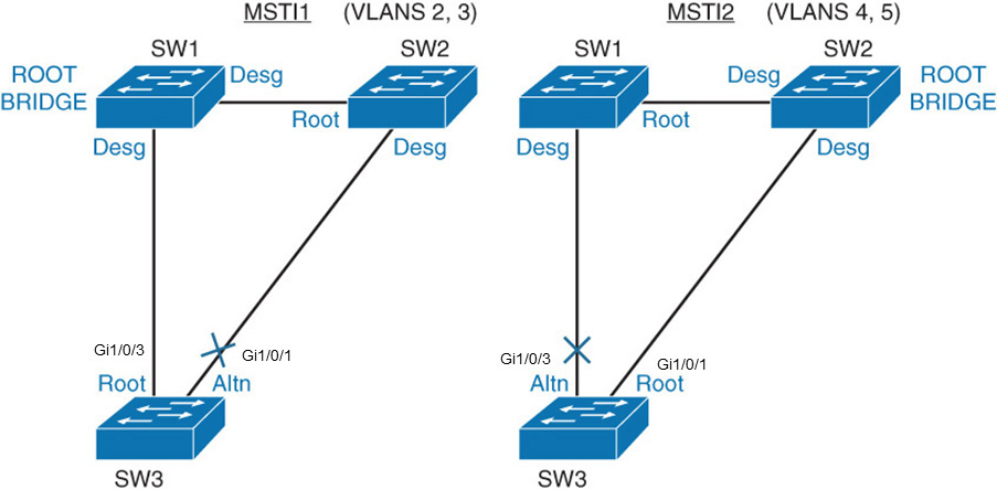
Figure 28-23 MST Configuration Topology
Configuring MST Path Cost and Port Priority
You can assign lower-cost values to interfaces that you want selected first and higher-cost values to interfaces that you want selected last. If all interfaces have the same cost value, MST puts the interface with the lowest sender port ID in the forwarding state and blocks the other interfaces.
To change the STP cost of an interface, enter interface configuration mode for that interface and use the command spanning-tree mst instance cost cost. For the instance variable, you can specify a single instance, a range of instances that are separated by a hyphen, or a series of instances that are separated by a comma. The range is 0 to 4094. For the cost variable, the range is 1 to 200000000; the default value is usually derived from the media speed of the interface.
You can assign higher sender priority values (lower numeric values) to interfaces that you want selected first and lower sender priority values (higher numeric values) to interfaces that you want selected last. If all sender interfaces have the same priority value, MST puts the interface with the lowest sender port ID in the forwarding state and blocks the other interfaces.
To change the STP port priority of an interface, enter interface configuration mode and use the spanning-tree mst instance port-priority priority command. For the priority variable, the range is 0 to 240, in increments of 16. The default is 128. The lower the number, the higher the priority.
Study Resources
For today’s exam topics, refer to the following resources for more study.