
Day 24. Network Cabling
CompTIA A+ 220-901 Exam Topics
![]() Objective 2.1: Identify the various types of network cables and connectors.
Objective 2.1: Identify the various types of network cables and connectors.
![]() Objective 2.2: Compare and contrast the characteristics of connectors and cabling.
Objective 2.2: Compare and contrast the characteristics of connectors and cabling.
Key Topics
The focus of this day is the various types of network cabling. We will explore the characteristics of the cables and the connectors used to terminate them. We also will discuss cabling standards and interference.
Fiber
Fiber-optic cable carries data represented by light waves. It is an extremely fast media that can carry data for very long distances. Also, because electricity is not used in the cable, fiber is not affected by electromagnetic interference (EMI) or radio frequency interference (RFI).
Single-mode Versus Multimode
The two types of fiber are single-mode and multimode. Single-mode fiber has a very small core (9 microns) and allows for a single path of light. Multimode fiber has a larger core (50/62.5 microns) and allows for multiple paths of light.
The amount of data that can be transferred over a network is known as bandwidth and is measured in bits over time. The time is most often per each second. Data is transferred one bit at a time, so bandwidth is how much data can be sent in 1 second. For example, if the bandwidth is 100 megabits per second, the notation is 100 Mb/s.
Single-mode fiber is most often used to carry bandwidth of more than 10 Gb/s over hundreds or even thousands of kilometers. It typically is used for cable TV and telephony applications. Single-mode fiber uses a laser to generate the light waves.
Multimode fiber is popular in networks when making backbone connections or connecting buildings. It can carry bandwidth of 10 Gb/s as far as 600 meters. Multimode fiber uses LEDs to generate the light waves.
Fiber-optic Cable Connectors
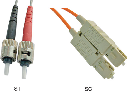
Three main types of connectors are used with fiber-optic cables: SC, ST, and LC. The ST and SC connectors are shown in Figure 24-1. These connectors are different sizes and have different ways of connecting to equipment:
![]() Subscriber connector (SC)—This connector is used with both single-mode and multimode fiber. It is square shaped and has a push-pull–type connection.
Subscriber connector (SC)—This connector is used with both single-mode and multimode fiber. It is square shaped and has a push-pull–type connection.
![]() Straight-tip (ST)—This connector is barrel-shaped and connects to equipment with a twist-to-lock–type connection.
Straight-tip (ST)—This connector is barrel-shaped and connects to equipment with a twist-to-lock–type connection.
![]() Lucent connector (LC)—Similar to the SC connector, it is square and connects with a push-pull–type connection, but it is much smaller than the SC connector.
Lucent connector (LC)—Similar to the SC connector, it is square and connects with a push-pull–type connection, but it is much smaller than the SC connector.
Twisted Pair
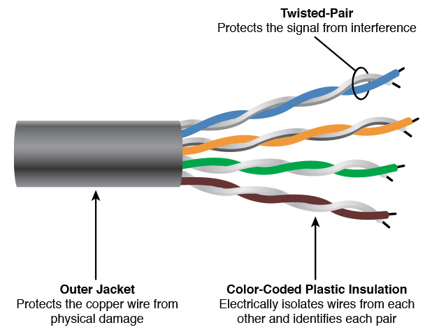
Twisted-pair (TP) cable is the most popular type of cable in networks today. The cable consists of four pairs of copper wires within an outer jacket. Each pair is twisted together to reduce interference from EMI and RFI, as shown in Figure 24-2. The most frequently used twisted-pair cable is unshielded twisted pair (UTP). UTP relies solely on the twists of the wires for shielding. Shielded twisted-pair (STP) cable also is available, but it is more expensive and more difficult to install. STP is often used in industrial environments for extra shielding.
The outer jacket of twisted-pair cable is made of polyvinyl chloride (PVC). This flexible, plastic material is easy and cheap to manufacture. One problem with PVC, though, is that if it catches fire, the fumes that are released are very toxic.
Many buildings have plenum areas. The plenum is an area used for airflow, often above a dropped-ceiling. This area is commonly used to route network cables. Special plenum-rated cables are used in these areas that do not produce toxic fumes when they burn.
Twisted-pair Cable Types
There are several types of twisted pair. These are referred to as Categories (CAT), and each has a different speed and different features, as shown in Table 24-1.
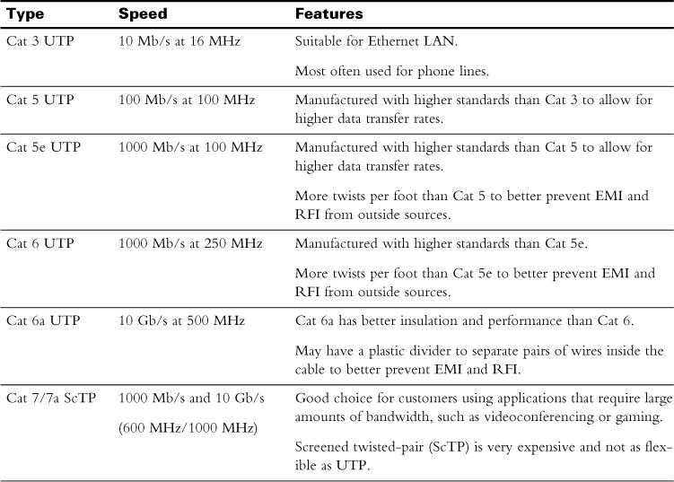
Table 24-1 indicates the theoretical maximum bandwidth of the cable. A cable with a maximum bandwidth of 100 Mb/s does not typically transfer all that data because of some limiting factors. The frequency of the cable, the rate at which the data is encoded, and the length of the cable are all factors that determine the throughput (actual speed of the data).
The maximum allowed length of Ethernet cable is 100 meters. It is not acceptable to split the cable to extend the distance or attach additional devices. Splitting the cable degrades signal quality.
Twisted-pair Cable Connectors
There are two connectors for terminating twisted-pair cabling: RJ-11 and RJ-45, also called the 8 Pin 8 Connector (8P8C). RJ-11 is the official name for a telephone plug. It is attached to both ends of Cat 3 cable to connect a telephone to an outlet. The RJ-11 connector can accommodate up to six wires.
The RJ-45 connector looks very much like the RJ-11 connector, but it is larger to accommodate up to eight wires. It is attached to both ends of all Cat 5 or better Ethernet cables.
The wires within cables have unique colors. Some are solid, while others are white with a colored stripe. Pairs of wires are identified as one solid colored wire and one wire striped with that color. The wires placed into the RJ-45 connector are in a very specific order. This order is known as a color code.
Twisted-pair Wiring Standards
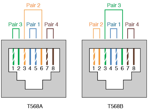
Two color codes are used with twisted pair cables, as outlined by the Telecommunications Industry Association/Electronic Industries Alliance (TIA/EIA) standards. These color code standards are T568A and T568B. The standards use the colors orange, green, blue, and brown.
Most Ethernet cables are known as straight-through and use the same color code at both ends. The most commonly used color code is T568B. Straight-through cables are used to connect computers to wall jacks, routers, and switches and are known as patch cables. They also are used to connect network devices together and patch between panels. It is possible to connect one computer to another, for transferring files very quickly for example, but the cable must use T568A on one end and T568B on the other end. This is known as a crossover cable.
The RJ-45 connector has eight spots for the wires to be terminated. These spots are commonly referred to as pins. Figure 24-3 shows the colors and the order in which they are placed into the RJ-45 connector.
Coaxial
Coaxial cable also can be used to transfer data. This type of cable typically is used by cable television companies to deliver Internet service. This is the same cable used to deliver video service to televisions and set-top boxes.
Coaxial Cable Types
Networks today use two main types of coaxial cable: RG-59 and RG-6. Both have a center conductor made of copper with an insulating material around it. Copper shielding surrounds the insulating material, which is surrounded by a jacket, as shown in Figure 24-4. RG-6 has replaced RG-59 because it has a larger conductor and better shielding.

RG-6 can connect devices up to 1,000 feet away with bandwidth reaching as high as 1 Gb/s. The amount of bandwidth depends on which frequencies are being used to transmit data and whether a service provider has set a data limit.
Coaxial cable frequently is split to accommodate more devices. For example, a home might have three televisions and a cable modem for Internet service. Splitters are used to reach each of these devices. The more splitters that are used, the less signal will reach each device downstream. Splitters reduce signal quality. In special installations, amplifiers might be used to overcome this reduction in signal.
Coaxial Cable Connectors
Coaxial cable uses two types of connectors, as shown in Figure 24-4:
![]() BNC—This connector is attached to a device by twisting it to lock it.
BNC—This connector is attached to a device by twisting it to lock it.
![]() F-connector—This connector is threaded and attaches to a device by twisting it until it is tight.
F-connector—This connector is threaded and attaches to a device by twisting it until it is tight.
Another type of coaxial cable connector, the N-type, usually is used only to join coaxial cables together.
![]() Activity 24-1: Compare Media Types
Activity 24-1: Compare Media Types
Refer to the Digital Study Guide to complete this activity.
Study Resources
For today’s exam topics, refer to the following resources for more study.

![]() Check Your Understanding
Check Your Understanding
Refer to the Digital Study Guide to take a quiz covering the content of this day.