
5. Articulated Motion and Morphing
This lesson will take approximately two and a half hours to complete. If needed, remove the previous lesson folder from your hard drive and copy the Lesson05 folder onto it.
![]()
You can easily create complex motion with articulations—joints between linked objects—with the feature called inverse kinematics. You can also morph—create organic changes in shapes—with shape tweens.
Getting Started
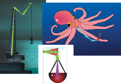
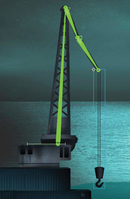
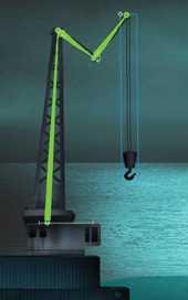
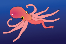
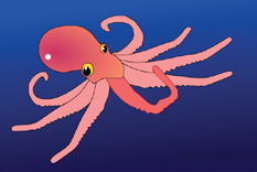
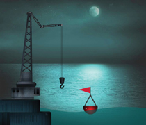
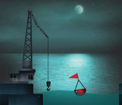
You’ll start the lesson by viewing the animated crane and floating buoy that you’ll create as you learn about articulated motion and morphing in Flash. You’ll also be animating a tentacle of an octopus.
1 Double-click the 05End.swf file in the Lesson05/05End folder to play the animation. Double-click the 05ShapeIK_End.swf to play that animation as well.
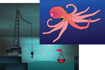
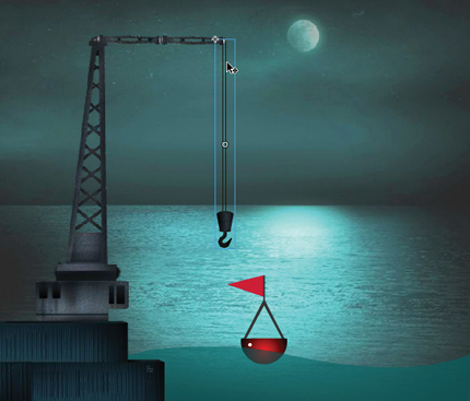
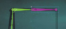
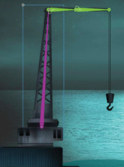
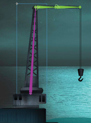
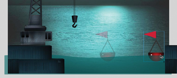
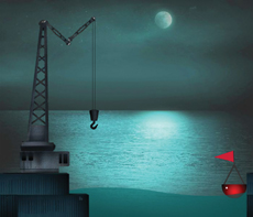
The first project is an animation depicting a crane working at the seaside dock and a buoy floating along the gentle undulations of the water. In this lesson, you’ll animate the crane arm, the buoy, and the smooth motion of the waves. The other project is an animation showing an octopus curling one of its tentacles.
2 Double-click the 05Start.fla file in the Lesson05/05Start folder to open the initial project file in Flash.
3 Choose File > Save As. Name the file 05_workingcopy.fla, and save it in the 05Start folder. Saving a working copy ensures that the original start file will be available if you want to start over.
Articulated Motion with Inverse Kinematics
When you want to animate an articulated object (one that has multiple joints), such as a walking person, or as in this example, a moving crane, Flash Professional CS5 makes it easy to do so with inverse kinematics. Inverse kinematics is a mathematical way to calculate the different angles of a jointed object to achieve a certain configuration. You can pose your object in a beginning keyframe, and then set a different pose at a later keyframe. Flash will use inverse kinematics to figure out the different angles for all the joints to get from the first pose to the next pose.
Inverse kinematics makes animating easy because you don’t have to worry about animating each segment of an object or limb of a character. You just focus on the overall poses.
Defining the bones
The first step to create articulated motion is to define the bones of your object. You use the Bone tool (![]() ) to do that. The Bone tool tells Flash how a series of movie clip instances are connected. The connected movie clips are called the armature, and each movie clip is called a node.
) to do that. The Bone tool tells Flash how a series of movie clip instances are connected. The connected movie clips are called the armature, and each movie clip is called a node.
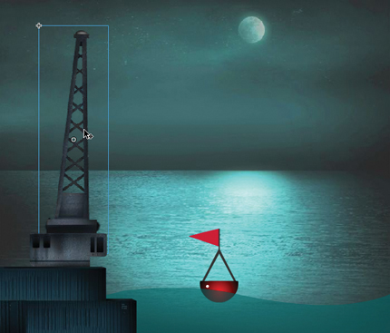
1 In your 05working_copy.fla file, select the crane layer. Lock all the other layers.
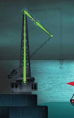
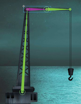
2 Drag the cranearm1 movie clip symbol from the Library panel onto the Stage. Place the instance right above the rectangular crane base.
3 Drag the cranearm2 movie clip symbol from the Library panel onto the Stage. Place the instance next to the tip of the cranearm1 movie clip instance.
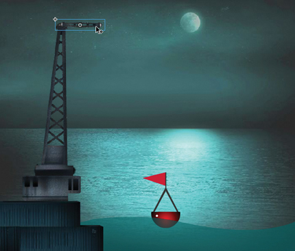
4 Drag another instance of the cranearm2 movie clip symbol from the Library panel onto the Stage. Place this instance next to the free tip of the first cranearm2 instance.
You’ll have two cranearm2 instances next to each other.

5 Drag the cranerope movie clip symbol from the Library panel onto the Stage. Place the instance so it hangs down from the last cranearm2 instance.
Your movie clip instances are now in place and ready to be connected with bones.
6 Select the Bone tool.
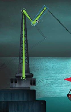
7 Click on the base of the cranearm1 instance and drag the Bone tool to the base of the cranearm2 instance. Release the mouse button.
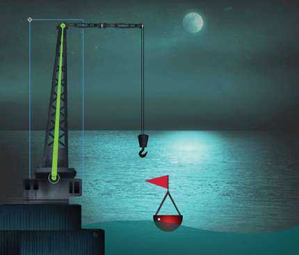
Your first bone is defined. Flash shows the bone as a skinny triangle with a round joint at its base and a round joint at its tip. Each bone is defined from the base of the first node to the base of the next node. For example, to build an arm, you would click on the shoulder side of the upper arm and drag it to the elbow side of the lower arm.
8 Click on the base of the cranearm2 instance and drag it to the base of the next cranearm2 instance. Release the mouse button.

Your second bone is defined.
9 Click on the base of the second cranearm2 instance and drag it to the base of the cranerope instance. Release the mouse button.
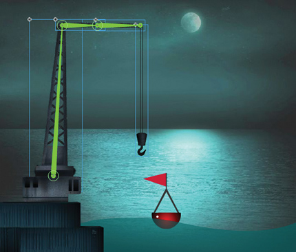
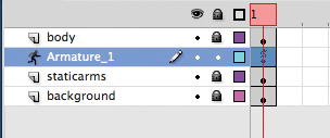
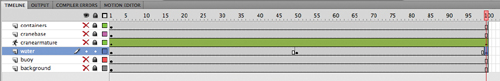
Your third bone is defined. Note that the four movie clip instances, which are now connected with bones, have been separated to a new layer with a new icon and name. The new layer is a Pose layer, which keeps your armatures separate from other objects on the Timeline such as graphics or motion tweens.
Armature Hierarchy
The first bone of an armature is referred to as the parent, and the bone that is linked to it is called the child. A bone can actually have more than one child attached to it as well. For example, an armature of a puppet would have a pelvis connected to two thighs, which in turn are attached to two lower legs of their own. The pelvis is the parent, each thigh is a child, and the thighs are siblings to each other. As your armature becomes more complicated, you can use the Properties inspector to navigate up and down the hierarchy using these relationships.
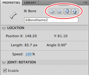
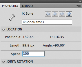
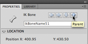
When you select a bone in an armature, the top of the Properties inspector displays a series of arrows.
You can click the arrows to move through the hierarchy and quickly select and view the properties of each node. If the parent bone is selected, you can click the down arrow to select the child. If a child bone is selected, you can click the up arrow to select its parent, or click the down arrow to select its own child if it has one. The sideways arrows navigate between sibling nodes.
10 Rename the Pose layer cranearmature and delete the empty crane layer that contained the initial movie clip instances.

Inserting poses
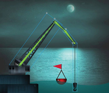
Think of poses as keyframes for your armature. You have an initial pose for your crane in frame 1. You will insert two additional poses for the crane. The next pose will position the crane down as if it were picking something up from the ocean. The last pose will position the crane back up to lift up the object.
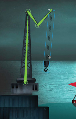
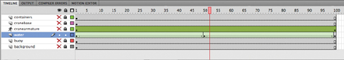
1 Move the red playhead to frame 50.
2 Using the Selection tool, click on the hook at the end of the cranerope instance and drag it down to the water.
A new pose is automatically inserted at frame 50. As you drag the cranerope instance, notice how the entire armature moves along with it. The bones keep all the different nodes connected.
3 Move the red playhead to frame 100 (the last frame).
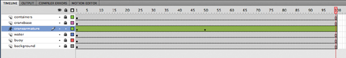
4 Click on the hook at the end of the cranerope instance and drag it up out of the water.
A new pose is automatically inserted at frame 100.
5 Preview the animation by choosing Control > Test Movie > in Flash Professional.
The crane animates, moving all its crane segments from one pose to the next.
Note
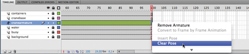
You can edit poses on the Timeline just as you can with keyframes of a motion tween. Right-click/Ctrl-click along the Timeline and choose Insert Pose to insert a new pose. Right-click/Ctrl-click on any pose and select Clear Pose to remove the pose from the layer. Ctrl-click/Command-click on a pose to select it. Click and drag the pose to move it to a different position along the Timeline.
Isolating the rotation of individual nodes
As you pull and push on the armature to create your pose, you may find it difficult to control the rotation of individual nodes because of their linkages. Holding down the Shift key as you move individual nodes will isolate their rotation.
1 Select the third pose at frame 100.
2 Holding down the Shift key, click and drag on the second node in the armature to rotate it so that it points downward.
The second node of the crane rotates, but the first node does not.
3 Holding down the Shift key, click and drag on the third node in the armature to rotate it so that it points upward.
The third node of the crane rotates, but the first and second nodes do not.
4 Holding down the Shift key, click and drag on the last node in the armature (the cranerope instance) so that it points straight down.
Holding down the Shift key helps you isolate the rotations of the individual nodes so that you can position your poses exactly as you want them. The crane now retracts by collapsing its different arm segments.
Constraining Joints
The various joints of the crane can freely rotate, which isn’t particularly realistic. Many armatures in real life are constrained to certain angles of rotation. For example, your forearm can rotate up toward your bicep, but it can’t rotate in the other direction beyond your bicep. When working with armatures in Flash Professional CS5, you can choose to constrain the rotation for various joints or even constrain the translation (movement) of the various joints.
Next, you’ll constrain the rotation and translation of the various joints of the crane so they move more realistically.
Constraining the rotation of joints
By default, the rotation of joints have no constraints, which means they can rotate in a full circle, or 360 degrees. If you only want a certain joint to rotate in a quarter circle arc, you would constrain the joint to 90 degrees.
1 Click the second pose at frame 50 in the cranearmature layer, right-click/Ctrl-click, and select Clear Pose.
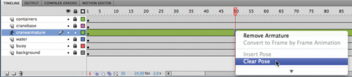
2 Click the third pose at frame 100 in the cranearmature layer, right-click/Ctrl-click, and select Clear Pose.
Your armature now has only a single pose at frame 1.
3 Move the red playhead to frame 1.
4 Choose the Selection tool.
5 Click on the second bone in the crane armature.
The bone becomes highlighted, indicating that it is selected.
6 In the Properties inspector, select the Constrain option in the Joint:Rotation section.
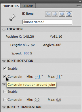
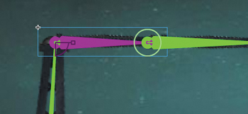
An angle indicator appears on the joint, showing the minimum and maximum allowable angles and the current position of the node.
7 Set the minimum joint rotation angle to 0 degrees and the maximum joint rotation angle to 90 degrees.
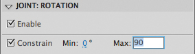
The angle indicator changes on the joint, showing the allowable angles. In this example, the second segment of the crane can only bend downward or rise up to be level with the horizon.
8 Click on the third bone in the crane armature.
The bone becomes highlighted, indicating that it is selected.
9 In the Properties inspector, select the Constrain option in the Joint:Rotation section.
An angle indicator appears on the joint, showing the minimum and maximum allowable angles and the current position of the node.
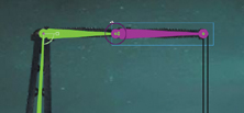
10 Set the minimum joint rotation angle to -90 degrees and the maximum joint rotation angle to 0 degrees.
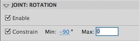
The angle indicator changes on the joint, showing the allowable angles. In this example, the third segment of the crane can only bend from a level position to a vertical position. Each joint in an armature can have its own rotation constraints.
Constraining the translation of joints
You don’t normally think of joints that can move positions. However, in Flash Professional CS5, you can allow joints to actually slide in either the x (horizontal) or the y (vertical) direction, and set the limits on how far those joints can travel.
In this example, you’ll allow the first node (the tall first segment of the crane) to move back and forth as if it was on a track. This will give it the capability to pick up any sort of cargo from the ocean and place it on the dock.
1 Click on the first node in the crane armature.
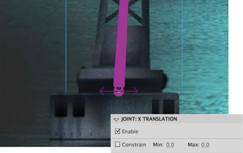
2 Deselect the Enable option in the Joint:Rotation section of the Properties inspector.
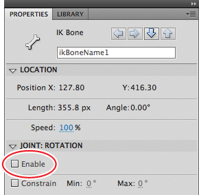
The circle around the joint disappears, indicating that it can no longer rotate.
3 Select the Enable option in the Joint:X Translation section of the Properties inspector.
Arrows appear from the joint, indicating that the joint can travel in that direction.
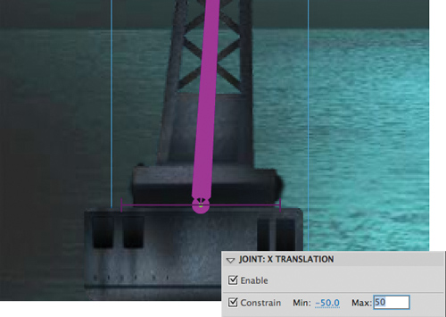
4 Select the Constrain option in the Joint:X Translation section of the Properties inspector.
The arrows turn into straight lines, indicating that the translation is limited.
5 Set the minimum X translation to -50 and the maximum X translation to 50.
The bars indicate how much translation in the x direction the first bone can do.
6 Grab the hook and pose the crane in the first keyframe so that the first node is close to the edge of the water and the hook is lowered.
7 Move the red playhead on the Timeline to the last frame.
Changing Joint Speed
Joint speed refers to the stickiness, or stiffness, of a joint. A joint with a low joint speed value will be sluggish. A joint with a high joint speed value will be more responsive. You can set the joint speed value for any selected joint in the Properties inspector.
The joint speed is apparent when you drag the very end of an armature. If there are slow joints higher up on the armature chain, those particular joints will be less responsive and will rotate to a lesser degree than the others.
To change the joint speed, click on a bone to select it. In the Properties inspector, set the joint Speed value from 0% to 100%.
8 Move the hook out of the water and the crane back from the edge of the water, creating a new pose.
The constraints on joint rotation and joint translation impose limits on the poses that help you create more realistic animations.
9 Watch your animation by choosing Control > Test Movie > in Flash Professional.
Inverse Kinematics with Shapes
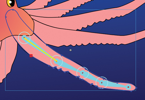
The crane is an armature made with various movie clip symbols. You can also create armatures with shapes, which are useful for animating objects without obvious joints and segments but can still have an articulated motion. For example, the arms of an octopus have no actual joints, but you can add bones to a smooth tentacle to animate its undulating motion.
Defining bones inside a shape
You’ll add bones to an octopus—perhaps one that was picked up by the crane from the ocean depths—and animate one of its tentacles.
1 Open the file 05ShapeIK_Start.fla. Choose File > Save As. Name the file 05ShapeIK_workingcopy.fla.
The file contains an illustration of an octopus. One arm is separated on its own layer called arm1.
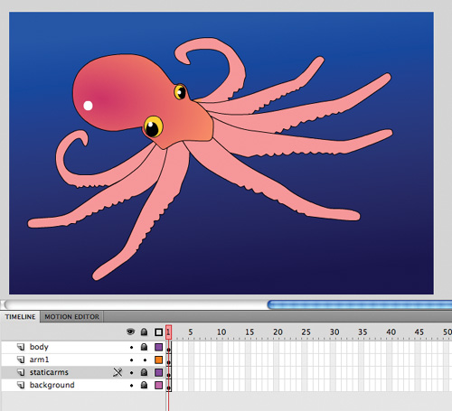
2 Lock all the layers except for the arm1 layer and select the contents of the arm1 layer.
3 Choose the Bone tool.
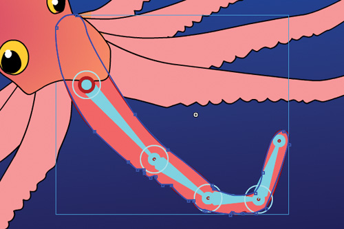
4 Click on the base of the tentacle in the arm1 layer and drag out the first bone a little ways down toward the tip of the tentacle.

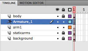
The first bone is defined. The contents of the arm1 layer are separated to a new Pose layer.
5 Click on the end of the first bone and drag out the next bone a little farther down toward the tip of the tentacle.
The second bone is defined.
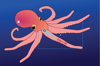
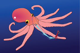
6 Continue building the armature with a total of four bones.
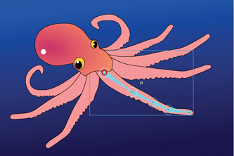
7 When the armature is complete, use the Selection tool to click and drag the last bone to see how the deformation of the tentacle follows the bones of the armature.
Editing the shape
You don’t need any special tools to edit the shape that contains bones. Many of the same drawing and editing tools in the Tools panel, such as the Paint Bucket, the Ink Bottle, and the Subselection tools, are available to you to edit the fill, the stroke, or the contours.
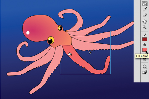
1 Choose the Paint Bucket tool.
2 Choose a dark peach color for the Fill.
3 Click on the shape in the Pose layer.
The fill color of the tentacle changes.
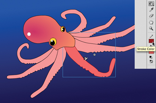
5 Choose a dark red color for the stroke.
6 Click on the shape in the Pose layer.
The outline of the tentacle changes color.
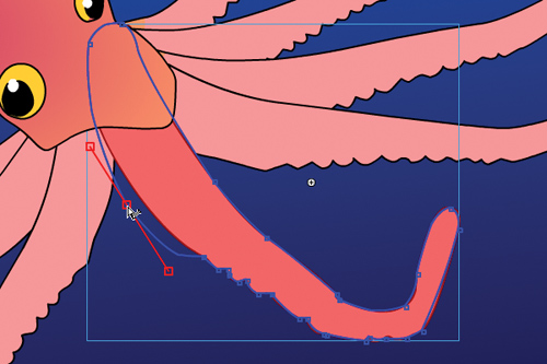
7 Choose the Subselection tool.
8 Click on the contour of the shape.
The anchor points and the control handles appear around the contour of the shape.
9 Drag the anchor points to new locations or click and drag the handles to make edits to the tentacle shape.
Note
Add new points on the contour of the shape with the Add Anchor Point tool. Delete points on the contour of the shape with the Delete Anchor Point tool. Both the Add Anchor Point and Delete Anchor Point tools are located under the Pen tool.
Editing the bones and armature
The Subselection tool can move the joints within a shape. However, the location of the joints within the shape can only be edited when you have a single pose for your armature. After your armature has been repositioned in later frames of the Pose layer, changes to the bone structure cannot be made.
Use the Selection tool if you want to move the entire armature to a different location but keep the bone structure unchanged.
1 Choose the Subselection tool.
2 Click on a joint.
3 Click and drag the joint within the shape to a new location.
4 Choose the Selection tool. Hold down the Alt/Option key and drag the entire armature to a new location.
Note
You can easily remove bones or add more bones to your armature. Choose the Selection tool and click on the bone you want to delete. Press the Delete key to remove the selected bone; all the child bones will be removed as well. Add new bones by choosing the Bone tool and clicking on the armature.
Refining the Shape Behavior with the Bind Tool
The organic control of a shape by its armature is a result of a mapping between the anchor points along the shape and its bones. The points along the tip of the tentacle, for example, are mapped to the very last bone, whereas the points farther up the tentacle are mapped to the bones farther up the tentacle. Hence, where the bones rotate, the shape follows.
You can edit the connections between the bones and their control points with the Bind tool (![]() ). The Bind tool is hidden under the Bone tool. The Bind tool displays which control points are connected to which bones and lets you break those connections and make new ones.
). The Bind tool is hidden under the Bone tool. The Bind tool displays which control points are connected to which bones and lets you break those connections and make new ones.
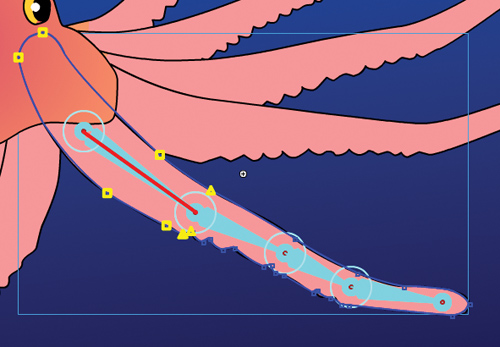
Choose the Bind tool and click on any bone in the shape. The selected bone is highlighted in red, and all the connected control points on the shape are highlighted in yellow.
If you want to redefine which control points are connected to the selected bone, you can do the following:
• Shift-click to add additional associations to control points.
• Ctrl-click/Command-click to remove associations to control points.
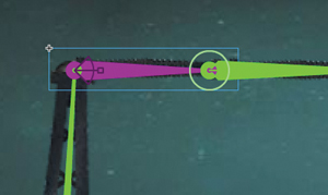
• Drag a connection line between the bone and the control point. In the following figure, a line is being dragged from the selected bone to a point on the left to make the association.

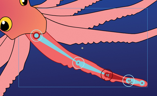
Click on any control point on the shape. The selected control point is highlighted in red, and all the connected bones are highlighted in yellow. In this figure, the red highlighted point is associated with the first bone.
If you want to redefine which bones are connected to the selected control point, you can do the following:
• Shift-click to add additional associations to bones.
• Ctrl-click/Command-click to remove associations to bones.
• Drag a connection line between the control point and the bone. In the following figure, another control point farther down the tentacle is being associated with the first bone.

Armature Options
Many settings are available through the Properties inspector that can help you make your armature interactive or help you apply easing to your armature motion. You can also choose different viewing options for your armature to suit your working style.
Authortime and runtime armatures
Authortime armatures are those that you pose along the Timeline and play as straightforward animations. Runtime armatures refer to armatures that are interactive and allow the user to move your armature. You can make any of your armatures—whether they are made with a series of movie clips such as the crane or made with a shape such as the octopus tentacle—into an authortime or a runtime armature. Runtime armatures, however, are restricted to armatures that only have a single pose.
1 Continue with the file 05ShapeIK_workingcopy.fla.
2 Select the layer containing the tentacle armature.
3 In the Properties inspector, select Runtime from the Type option.
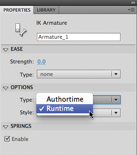
The armature becomes a runtime armature, allowing the user to directly manipulate the octopus tentacle. The first frame of the Pose layer displays the armature icon to indicate that the runtime option is selected and no additional poses can be added.
4 Test your movie by choosing Control > Test Movie > in Flash Professional.
The user can click and drag the tentacle and interactively move it on the Stage.
Controlling easing
The Motion Editor and its sophisticated controls for easing cannot be used with armatures. However, there are a few standard eases available from the Properties inspector that you can apply to your armatures. Easing can make your armature move with a sense of gravity due to acceleration or deceleration of its motion.
1 Select the layer containing the tentacle armature.
2 In the Properties inspector, select Authortime for Type in the Options section.
The armature becomes an authortime armature again.
3 Select frame 40 for all the layers and choose Insert > Timeline > Frame.
Frames are inserted in all the layers, giving you room on the Timeline to create additional poses for the tentacle.
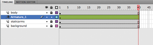
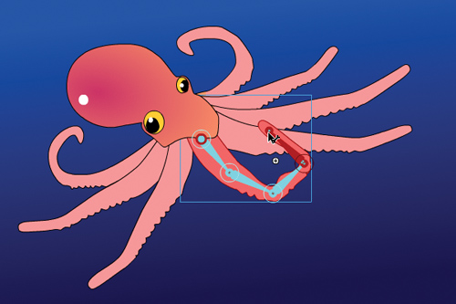
4 Move the red playhead to frame 40.
5 With the Selection tool, grab the tip of the tentacle, curl it upward, and move it to one side.
A new pose is inserted in frame 40 for the tentacle armature.
6 Select the first pose in frame 1 of the Armature layer.
7 In the Properties inspector, select Simple (Medium) for the Type under the Ease section.
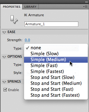
The variations of Simple eases (from Slow to Fastest) represent the severity of the ease. They represent the same curvatures provided in the Motion Editor for motion tweens.
8 Set the Strength to 100.
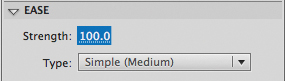
The Strength represents the direction of the ease. A negative value is an ease-in and a positive value is an ease-out.
9 Choose Control > Test Movie > in Flash Professional to preview your animation.
The tentacle curls up, easing out of its motion gradually.
10 Close the Test Movie window.
11 Select the first pose in frame 1.
12 Change the Strength setting to -100 and test your movie again.
The tentacle curls up, but the motion now eases in, starting slowly and gradually speeding up.
13 Close the Test Movie window.
14 Select the first pose in frame 1.
15 In the Properties inspector under the Ease section, select Start and Stop (Medium) for Type.
The variations of Stop and Start eases (from Slow to Fastest) represent the severity of the ease. The Stop and Start eases have curves on both ends of the motion, so the easing values affect the start of the motion and the end of the motion.
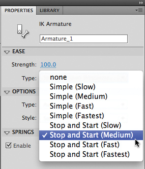
16 Set the Strength to -100.
17 Choose Control > Test Movie > in Flash Professional to preview your animation.
The tentacle curls up, easing into its motion gradually and also easing out of its motion gradually.
Morphing with Shape Tweens
Shape tweening is a technique for interpolating amorphous changes between shapes in different keyframes. Shape tweens make it possible to smoothly morph one thing into another. Any kind of animation that requires that the contours of a shape change—for example, animation of clouds, water, or fire—is a perfect candidate for shape tweening.
Both the fill and the stroke of a shape can be smoothly animated. Because shape tweening only applies to shapes, you can’t use groups, symbol instances, or bitmap images.
Establish keyframes containing different shapes
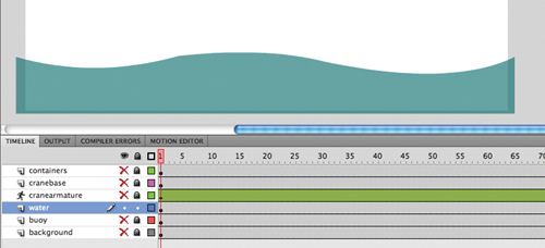
In the following steps, you’ll animate the gently undulating surface of the ocean beneath the crane with a shape tween.
1 Continue with the file of the crane animation called 05_workingcopy.fla.
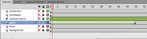
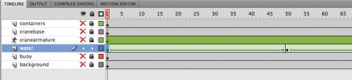
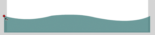
2 Lock and hide all the layers except for the water layer. The water layer contains a transparent blue shape at the bottom of the Stage.
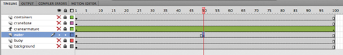
3 Move the red playhead to frame 50 in the water layer.
4 Right-click/Ctrl-click on frame 50 in the water layer and select Insert Keyframe. Or, choose Insert > Timeline > Keyframe (F6).
A new keyframe is inserted at frame 50. The contents of the previous keyframe are copied into the second keyframe.
5 Move the red playhead to frame 100.
6 Right-click/Ctrl-click on frame 100 in the water layer and select Insert Keyframe. Or, choose Insert > Timeline > Keyframe (F6).
A new keyframe is inserted at frame 100. The contents of the previous keyframe are copied into this keyframe. You now have three keyframes on the Timeline in the water layer: one at frame 1, a second at frame 50, and a third at frame 100.
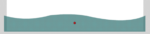
7 Move the red playhead back to frame 50.
Next, you’ll change the shape of the water in the second keyframe.
8 Choose the Selection tool.
9 Click and drag the contours of the water shape so that the crests become dips and the dips become crests.
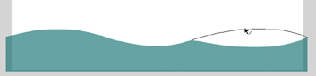
Each subsequent keyframe in the water layer contains a different shape.
Apply the shape tween
The next step is to apply a shape tween between the keyframes to create the smooth transitions.
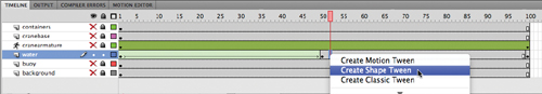
1 Click on any frame between the first keyframe and the second keyframe in the water layer.
2 Right-click/Ctrl-click and select Create Shape Tween. Or, from the top menu choose Insert > Shape Tween.

Flash applies a shape tween between the two keyframes, which is indicated by a black forward-pointing arrow.
3 Click on any frame between the second keyframe and the last keyframe in the water layer.
4 Right-click/Ctrl-click and select Create Shape Tween. Or, choose Insert > Shape Tween.
Flash applies a shape tween between the last two keyframes, which is indicated by a black forward-pointing arrow.
5 Watch your animation by choosing Control > Test Movie > in Flash Professional. Flash creates a smooth animation between the keyframes in the water layer, morphing the shape of the ocean surface.
Note
The Motion Editor is not available for shape tweens.
Using Shape Hints
Shape hints force Flash to map points on the first shape to corresponding points on the second shape. By placing multiple shape hints, you can control more precisely how a shape tween appears.
Adding shape hints
Now you’ll add shape hints to the shape tween of the wave to modify the way it morphs from one shape to the next.
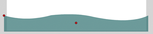
1 Select the first keyframe of the shape tween in the water layer.
2 Choose Modify > Shape > Add Shape Hint (Ctrl+Shift+H/Command+Shift+H).
A red circled letter “a” appears on the Stage. The circled letter represents the first shape hint.
3 Drag the circled letter to the top-left corner of the ocean shape.
Shape hints should be placed on the contours of shapes.
4 Choose Modify > Shape > Add Shape Hint again to create a second shape hint.
A red circled “b” appears on the Stage.
5 Drag the “b” shape hint to the top edge of the ocean shape at the bottom of a dip of the wave.

6 Add a third shape hint.
A red circled “c” appears on the Stage.

7 Drag the “c” shape hint to the far top-right corner of the ocean shape.
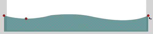
You have three shape hints mapped to different points on the shape in the first keyframe.
8 Select the next keyframe of the water layer (frame 50).
A corresponding red circled “c” appears on the Stage, although an “a” and a “b” shape hint are directly under it.
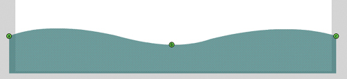
9 Drag the circled letters to corresponding points on the shape in the second keyframe. The “a” hint goes on the top-left corner, the “b” hint goes on the bottom of the wave, and the “c” hint goes on the top-right corner.
The shape hints turn green, indicating that you’ve correctly placed the shape hint.
10 Select the first keyframe.
Note that the initial shape hints have turned yellow, indicating that they are correctly placed.

11 Choose Control > Test Movie > in Flash Professional to see the effects of the shape hints on the shape tween.
The shape hints force the crest of the first shape to map to the crest of the second shape, causing the shape tween to appear more like a traveling wave instead of an up-and-down bobbing motion.
Note
You can add a maximum of 26 shape hints to any shape tween. Be sure to add them in a clockwise or counterclockwise direction for best results.
Removing shape hints
If you’ve added too many shape hints, you can easily delete the unnecessary ones. Removing a shape hint in one keyframe will remove its corresponding shape hint in the other keyframe.
• Drag an individual shape hint entirely off the Stage and Pasteboard.
• Choose Modify > Shape > Remove All Hints to delete all the shape hints.
Simulating Physics with Inverse Kinematics
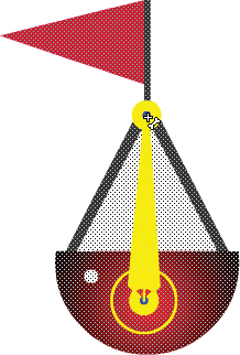
Now that you’ve animated the undulating water beneath the crane, it would be nice to see the red buoy move along the surface as well. You could create a motion tween so it travels along the water. However, since the buoy has a flexible flag attached, it’ll be more realistic to see the flag and the pole wave and bend as the buoy moves. Flash Professional CS5 introduces a new feature for inverse kinematics called Spring that helps you do this easily.
The Spring feature simulates physics in any animated armature. A flexible object (like a flag or a flag pole) normally would have some “springiness” that would cause it to jiggle on its own as it moves, and continue to jiggle even after motion of the entire body stops. The amount of springiness can be set for each bone in an armature to help you get the exact amount of rigidity or flexibility in your animation.
Define bones for your armature
In the following steps, you’ll animate the buoy floating across the water and set the strength of the spring in each of the bones in the armature of the buoy. The first step is to add bones to the shape of the buoy.
1 Lock and hide all the layers except for the buoy layer and select the contents of the buoy layer.
2 Choose the Bone tool.
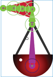
3 Click on the base of the buoy and drag out the first bone to the tip of the triangular support at the bottom of the flag pole.
The first bone is defined. The contents of the buoy layer are separated to a new Pose layer.
4 Click on the end of the first bone and drag out the next bone a little farther up the flag pole.

The second bone is defined.
5 Click on the end of the second bone and drag out the next bone to the left into the flag.
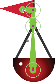
6 Define two more bones to extend the armature to the tip of the flag.
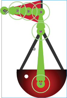
The bones in the flag will help the flag wave realistically. The bone in the flag pole will help the pole bend separately from the floating bottom.
Note
The Spring feature for inverse kinematics works for both armatures in shapes and armatures with movie clips.
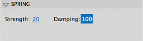
Setting the spring strength for each bone
Next, you’ll set the strength value for the spring for each bone. The strength value can range from 0 (no spring) to 100 (maximum spring).
1 Select the last bone (at the tip of the flag) of the armature in the buoy.
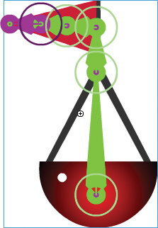
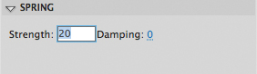
2 In the Properties inspector, in the Spring section, enter 100 for the Strength.
The last bone has the maximum spring strength since the flag tip is the most flexible part of the whole buoy and would have the most independent motion.

3 Select the next bone in the armature hierarchy. It may be difficult to select the next adjacent bone if they are too crowded together, so you can choose the Parent button in the Properties inspector to move up the hierarchy.
4 In the Properties inspector, in the Spring section, enter 60 for the Strength.
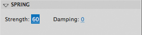
The middle of the flag is a little less flexible than the tip, so it has a smaller strength value.
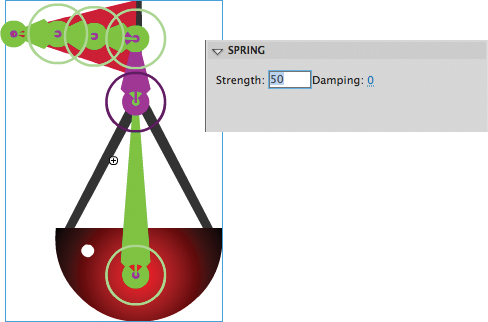
5 Select the next adjacent bone, and in the Properties inspector, in the Spring section, enter 20 for the Strength.
The base of the flag is even less flexible than the middle of the flag, so it has an even smaller strength value.
6 Select the next adjacent bone (the bone within the pole), and in the Properties inspector, in the Spring section, enter 50 for the Strength.
Giving the pole a medium amount of spring strength will make the pole bend back and forth on the buoy.
Insert the next pose
Next, you’ll move the buoy across the water and watch how its horizontal motion affects the movement of the individual bones in the armature.
1 Unhide all the layers so you can see where the buoy is located on the scene.
2 Select frame 70 of the armature layer, which contains your buoy.
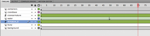
3 Holding down the Alt/Option key, click and drag the buoy and move it to the right so it meets the shipping containers on the edge of the Stage.
Holding down the Alt/Option key allows you to move the entire armature around the Stage.
4 Choose Control > Test Movie > in Flash Professional to see the motion of the buoy and its attached flag.
Note
The effects of the Spring feature are more apparent when there are additional frames on the Timeline after the armature’s final pose, as in this lesson. The additional frames allow you to see the residual bouncing effect after the motion stops.
The buoy moves from left to right. At the same time, the flag pole bends and the flag sways. When the buoy stops at the edge of the Stage, the pole and the flag continue to move.
Refining armature spring values
Although the flexibility of the flag and the pole on the buoy gives the animation more realism, the floating bottom should also rock as it moves. In this section, you’ll refine your armature by adding some spring to the first bone in the buoy.
1 Lock and hide all the layers except for the armature layer containing the buoy and select the first bone.
2 In the Properties inspector, in the Spring section, enter 20 for the Strength.
Giving a spring value to the first bone makes it sway back and forth with any motion of the entire armature.
3 Choose Control > Test Movie > in Flash Professional to see your refinements to the motion of the buoy.
Now, as the buoy moves from left to right, it rocks as if floating on water. The flag and flag pole continue to sway.
Adding damping effects
Damping refers to how much the spring effect decreases with time. It wouldn’t be realistic if the rocking of the buoy or the swaying of the flag and the flag pole continues indefinitely. Over time, the swaying should lessen and eventually stop. You can set a damping value from 0 (no damping) to 100 (maximum damping) to control how rapidly these effects diminish.
1 Select the first bone of the buoy (in the floating part), and in the Properties inspector, in the Spring section, enter 100 for the Damping.
The maximum damping value will decrease the rocking of the buoy over time.
2 Continue to select each of the bones of the armature and enter the maximum value (100) for Damping.
3 Choose Control > Test Movie > in Flash Professional to see the effects that the damping values have on the motion of your buoy.
The buoy and the flag and flag pole still sway, but their motion quickly subsides after the initial starting motion and after the buoy stops at the far right side of the Stage. The damping values help add a sense of weight to the armature. Experiment with both the strength and damping values in the Spring section of your armature to get the most realistic motion.
Review Questions
1 What are the two ways of using the Bone tool?
2 What is the Bind tool used for?
3 Define and differentiate these terms: a bone, a node, a joint, and an armature.
4 What is a shape tween, and how do you apply it?
5 What are shape hints, and how do you use them?
6 What does strength and damping refer to in the Spring feature?
Review Answers
1 The Bone tool can connect movie clip instances together to form an articulated object that can be posed and animated with inverse kinematics. The Bone tool can also create an armature for a shape, which can be posed and animated with inverse kinematics as well.
2 The Bind tool can redefine the connections between the control points of a shape and the bones of an armature. The connections between the control points and the bones determine how the shape reacts to the bending and rotations of the armature.
3 Bones are the objects that connect individual movie clips together or that make up the internal structure of a shape for motion with inverse kinematics. A node is one of the movie clip instances that have been linked with the Bone tool. A node can be described in terms of its relationship with other nodes, such as parent, child, or sibling. Joints are the articulations between bones. Joints can rotate as well as translate (slide in both the x and y directions). Armatures refer to the complete articulated object. Armatures are separated on a special Pose layer on the Timeline where poses can be inserted for animation.
4 A shape tween creates smooth transitions between keyframes containing different shapes. To apply a shape tween, create different shapes in an initial keyframe and in a final keyframe. Then select any frame between the keyframes in the Timeline, right-click/Ctrl-click, and select Create Shape Tween.
5 Shape hints are labeled markers that indicate how one point on the initial shape of a shape tween will map to a corresponding point on the final shape. Shape hints help refine the way the shapes will morph. To use shape hints, first select the initial keyframe of a shape tween. Choose Modify > Shape > Add Shape Hint. Move the first shape hint to the edge of the shape. Move the playhead to the final keyframe, and move the corresponding shape hint to a matching edge of the shape.
6 Strength is the amount of springiness of any individual bone in an armature. Add springiness with the Spring feature to simulate the way different parts of a flexible object jiggle when the entire object moves and continue to jiggle when the object stops. Damping refers to how quickly the springiness effect subsides over time.