CHAPTER 3
Drawing Shapes in Flash
Flash comes with a variety of drawing tools that enable you to create a wide range of artwork for your rich media content.
- Drawing standard shapes
- Understanding merge vs. object drawing
- Drawing primitive shapes
- Drawing polygonal or star shapes with the PolyStar tool
- Making artsy shapes with the Deco tool
- Drawing other shapes
- Working with color in Flash
Drawing Standard Shapes
Rectangles and ovals are two of the standard Flash shapes you can use to create basic artwork, or you can combine them to form more intricate drawings.
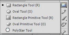
On the Flash Tools panel clicking the arrow on the basic shapes tool button displays a drop-down with five possible selections (see Figure 3.1). The first item listed (and the default tool if you click the button once and not twice) is the Rectangle tool. (Remember that any buttons with a tiny black triangle in their lower right-hand corner indicate there are multiple choices in that particular button group.) The second standard shape is the Oval tool. Having selected a shape tool other than the Rectangle tool, the new tool becomes the current button selection until another tool is selected. In other words, you want to work with the Oval tool, so you select it. Now the Oval tool is the tool that shows up on the face of the shapes button and does not change until you select a different tool.
You can also select the Rectangle tool by pressing the hotkey R on your keyboard, and you can select the Oval tool by pressing the hotkey O.
If this is the first time you’ve used the Tools panel, you’ll be in Merge Drawing mode, depicted by the button near the bottom of the Tools panel being “off”  . The other mode is Object Drawing mode, depicted by the same icon being “on”
  . It’s important to pay attention to the drawing modes (covered in detail in the section “Understanding Merge vs. Object Drawing”).
Let’s begin your Flash drawing experience by drawing a couple of basic shapes:
1. Click the Rectangle tool button or press R on the keyboard to activate the tool.
Flash also has the ability to import Illustrator and Photoshop drawings natively, which means for your more complex artwork, you can use Illustrator to create your assets and then simply import them into Flash when you’re done.
2. Make sure you are currently in Merge Drawing mode by checking the Tools panel button shown before this exercise. If you’re in Merge Drawing mode, the button will not have a dark-gray square around it. If this button is clicked, there will be a dark-gray square surrounding the button, which means you are in Object Drawing mode.
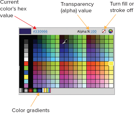
3. Now you need to select the
fill color, or inside color, for the object. The fill color is denoted by a tipping paint bucket in the Property Inspector (see
Figure 3.2). When you click the icon, you will open the Color Picker (
Figure 3.3), which allows you to select the fill color you want for your shape. You can enter the hexadecimal value of a color if you know it. Set the transparency for the color (0 = fully transparent, 100 = fully opaque), or completely turn off the fill color.
Make sure to check whether you are in Merge or Object Drawing mode every time you intend to create a drawing object.
One special kind of color option is a gradient, which is a mixture of colors, useful when you want a 3D look. I’ll cover the Gradient tool in Chapter 9 - Techniques for Creating More Technical Animations.
Copying an Exact Color
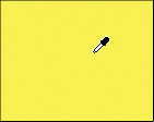
Once the Color Picker is open and you’re in the process of selecting a color, you don’t have to select it off of the color list, you can sample your color from any object on the stage. The cursor turns into an eyedropper (shown here). Any color you click within an object becomes the new fill color. This is tremendously useful for capturing colors such as skin tones in photographs and similar uses.
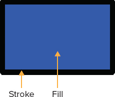
4. The other selection you make in the Property Inspector is the stroke, which is the outline around the shape you’re drawing. When you are drawing objects, you must decide whether to have a stroke on an object because it is not required. Your decision will depend on what kind of drawing you’re trying to create. For the purpose of this exercise, select a stroke color for your rectangle.
5. In the Property Inspector, just below the fill and stroke Color Pickers you’ll see a slider button that allows you to change the size of the stroke. You can either click in the number area or move the slider to change the stroke size. Change the stroke size to 10.
6. Click and drag to draw a rectangle on the stage (see
Figure 3.4).
Holding the Shift key while you draw with the Rectangle tool constrains it to be an exact square. Holding Shift while drawing with the Oval tool creates a perfect circle.
As long as the Rectangle tool stays selected, you can continue to draw various rectangles. For this exercise, draw several on the stage.
7. Change to the Selection tool

using the keyboard’s V key.
8. Click the outer edge of one of your rectangles, noting that just one side of the stroke is selected. Whenever a drawing object is selected like this, it’s easy to spot the active selection because it changes from a smooth color to a granulated view in which the individual pixels of the object are highlighted. Change the stroke color on one side.
9. With the new stroke color still active, click and drag the side away, noting that the rest of the rectangle object elements—both fill and stroke—stay where they’re at.
10. Press Ctrl+Z (Command+Z on the Mac) to undo the move.
11. Click the fill area, making it active. Change the fill color using the Color Picker.
12. Double-click the fill area, noting that both the fill and the stroke become selected.
13. Hold down the Shift key and then double-click another rectangle. Flash selects both objects’ fill and stroke.
14. Click anywhere on the stage or pasteboard to deactivate the rectangles. This is how you will ensure no objects are currently active when you’re getting ready to perform another activity.
Both the fill and the stroke must be selected when in Merge Drawing mode should you desire to move the object; otherwise, you’ll move just the fill, leaving the stroke behind.
15. Making sure you’re close to a rectangle but somewhere outside it, click and hold the mouse to draw a marquee (which always describes a rectangle or a square) around the rectangle. Both the fill and stroke become active.
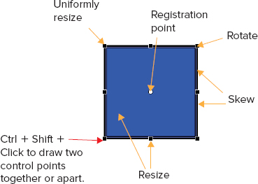
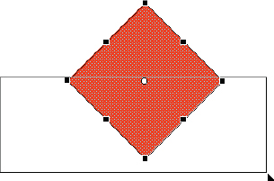
16. Press the Q key on your keyboard to activate the Free Transform tool, allowing you to perform complex sizing, skewing, and rotation operations on the object (see
Figure 3.5). You can also adjust the object’s registration point.
17. With the Free Transform tool still enabled, point your mouse close to a black box at one of the corners of the object (each black box is called a control point). The mouse cursor turns to a circular arrow, meaning you can now rotate the object. Rotate the object once or twice using different corners to observe the behavior.
18. Point your mouse directly over one of the corner control points. Now a double-headed mouse cursor appears, meaning you can enlarge or reduce the object’s size. If you hold down the Shift key, you can constrain the object’s proportions while resizing. Practice resizing the rectangle object.
You can press Ctrl+Z (Command+Z on the Mac) to undo your previous step.
19. Clicking the control point boxes in the middle of the lines allows you to click and drag to resize the width or height of the object. Holding down the Shift key retains the object’s proportions. Practice resizing your rectangle object a couple of times.
20. Holding down both the Ctrl and Shift keys (Command and Shift keys on the Mac), point to one of the corner point boxes. The mouse cursor changes to a white arrow with a tiny double-headed black arrow beside it. This means you can click and drag the corner control point in toward its neighbor or away from its neighbor to make a triangular or trapezoid shape.
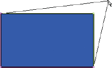
21. With the Free Transform tool still enabled, point to any of the connective bars around the object. The mouse cursor changes to a double-headed arrow with one tip of the arrow missing on each side (see
Figure 3.6). Now when you click and drag, you can
skew the object, moving one side out of alignment with its opposite neighbor. This is useful for perspective drawing work and creating uneven trapezoidal shapes. Practice skewing a couple of times, repeatedly using Ctrl+Z to undo your work.
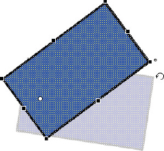
22. Note the registration point in the center of the object. When the Free Transform tool is active, you can move the registration point, which alters the object’s pivot point. Click the registration point of the object and then drag it to a corner.
23. Attempt to rotate the object, noting that the object now rotates around the new registration point (see
Figure 3.7).
24. Press Ctrl+Z twice to undo the registration point changes.
The Oval tool works essentially the same way as the Rectangle tool except when you click the stroke of an oval, the entire stroke becomes active.
25. Repeat all of these steps with the Oval tool, drawing several circles with different fill and stroke colors.
26. Deactivate all the objects by clicking somewhere in the stage or pasteboard.
27. Click the Subselection tool (hotkey A)

, which allows you to select specific points on an object so you can alter them, thus sculpting the object into more complex shapes. Note that when you’re using the Subselection tool, the control points look a little different, as does the cursor.
28. When you point to a control point, the cursor changes from a white arrow with a white square to a white arrow with a black square. This means you can click and drag the motion path to obtain a unique shape (see
Figure 3.8).
29. Practice altering the rectangle using the Subselection tool points. How does this compare with using Ctrl+Shift to resize a rectangle or square using Free Transform tool control points, as shown in
Figure 3.6.
30. With the Subselection tool selected, marquee one of the circles you drew on the stage. Note that there are many more control points that make up a circle versus the number used for a rectangle.
31. Click in the stage or pasteboard to deactivate all objects.
32. Press V to activate the Selection tool.
33. Marquee just one-quarter to one-third of any one of your rectangles or circles. When you let go of the mouse button, note that just the area of the rectangle or circle you marqueed becomes active.
34. Press the Delete key. The section you marqueed is deleted. When objects are in Merge Drawing mode, this is how you can delete parts of them for shaping purposes.
35. Click the stage or pasteboard to deactivate all objects.
36. Press the V key to activate the Selection tool.
37. Point to a side of one of your rectangle objects. Note that as you get close to the edge of the stroke, the mouse cursor changes to a black arrow with an arc underneath it. This means you can drag up or down to create an arc in the shape.
38. With the special cursor displayed, click the stroke of one of your rectangle objects and drag up to create an arc.
39. From the main menu, choose File

Save As. Browse to the folder in which you’d like to save your work and then name this practice file. Note that the filename extension is
.fla, meaning it is a working Flash document.
We will go through an exercise later in this chapter to work with the other drawing tools: Rectangle Primitive, Oval Primitive, and Star. But for now, it’s important that you understand the difference between Merge and Object Drawing modes because there are significant differences in the way objects behave when they are created using one or the other.
Understanding Merge vs. Object Drawing
The key to drawing in Flash is to think about the basic shapes that make up an object and then build the object using basic Flash shapes and modifying them to fit. This is where an understanding of the difference between Merge and Object Drawing modes comes into play.
Creating Objects in Merge Drawing Mode
When you’re using Flash’s basic shapes to draw assets, it’s quite important to understand whether you’re in Merge or Object Drawing mode. We’ll touch on Merge Drawing first:
1. Draw a marquee around all of the objects on the stage and then press the Delete key to erase them.
2. Make sure the shape button is still active from the previous exercises. If it is not, click the shape button or press the R key (rectangle) or O key (oval) to draw a shape.
3. You will know you’re in Merge Drawing mode when you see that the Merge/Object Drawing button is off, in other words, without a dark gray background. When this button is on, the background is darkened and you are in Object Drawing mode. Make sure you’re currently in Merge Drawing mode.
When you’re in Merge Drawing mode, objects that you draw and place on one another will merge to form a more complex shape.
The Merge/Object Drawing button does not show up until you click a shape button in the Tools panel.
4. This time, when you create a rectangle or circle, make sure there is no stroke selected. Create a basic drawing object.
5. Click the stage or pasteboard to deactivate the new object.
6. If you drew an oval, now select the Rectangle tool and draw a new rectangle on the stage, or vice versa if you first drew a rectangle.
7. If the second object is not active, you can double-click it to make it so. Move the second object over on top of but not completely obstructing the first.
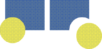
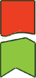
8. If you drop the second object onto the first, the second object stays active until you click away from it (see
Figure 3.9, left side). If you drop one shape onto another while in Merge Drawing mode and then move the shape away, you’ll see that you’ve eaten a piece out of the underlying shape (see
Figure 3.9, right side). Shapes that are made up of the same color and that have no strokes will merge together, which is a great way to create complex objects from basic shapes.
When you use the Free Transform and Subselection tools while in Merge Drawing mode to sculpt a shape and then merge it with other shapes, you can create some very intricate drawings. You are not limited to how many shapes you merge, nor their color. Designers who are comfortable boiling down complex things into their basic shapes will immediately be successful using the Flash drawing tools to create whatever they want.
Another useful technique with Merge Drawing is to draw a marquee by clicking and dragging around a part of the shape and then pressing Delete to erase the part you’ve marqueed, as you learned in steps 32 and 33 of the previous section, “Drawing Standard Shapes.”
Suppose, for example, you want to create an equilateral triangle. Here’s how:
1. Draw a perfect square by holding down the Shift key while you draw a rectangle.
2. Use the Free Transform tool to rotate the square 90 degrees.
3. Marquee the bottom half of the square and you have your triangle (see
Figure 3.10).
Finally, once you have all of your shapes drawn into the object you’re looking for and assembled them the way you want them, most times you will want to marquee the final product and turn it into a graphic object (more on this in Chapter 6, “Working with Flash Symbols”).
The square around an object may trick you into thinking you’ve somehow selected a stroke when you’re drawing a rectangle. No worries—you’re just in Object Drawing mode. The same movement and resizing tools apply.
Creating Objects in Object Drawing Mode
When the Object Drawing button is clicked (in other words, its background is dark gray), you don’t have to worry about one object eating away another. Objects created using Object Drawing mode have a square around them (which is not visible when the movie plays) and can be moved anywhere you desire. Figure 3.11 shows several objects drawn on the stage using Object Drawing mode.
Let’s work a little bit with drawing shapes using Object Drawing mode:
1. Click the stage or pasteboard to deactivate all objects.
2. Press the V key to activate the Selection tool.
3. Draw a marquee around all objects.
4. Press Delete to erase all objects on the stage.
5. Press the R key to activate the Rectangle tool.
6. Check the bottom of the Tools panel to make sure you’re in Object Drawing mode.
7. Select a fill and stroke color.
8. Draw a rectangle.
9. Repeat steps 5 through 8, this time pressing the O key to draw an oval instead of a rectangle.
10. Press the V key to activate the Selection tool. The oval you just drew should be the active object, provided you did not click away from it after drawing it.
11. Move the oval onto the top of the rectangle.
12. Note that the oval keeps its square boundary as you move it onto the rectangle.
13. Move the oval away from the rectangle, noting that no alterations have occurred on the rectangle.
Drawing Primitive Shapes
 The Rectangle Primitive and Oval Primitive tools work essentially the same way as the standard shapes. The difference is that when you create a shape using Rectangle or Oval primitives, you can alter that shape after you’ve drawn it on the stage. Also, you don’t have the choice of Merge or Object Drawing mode—all primitive shapes are drawn using primitive-drawing mode. Follow these steps to learn how to add corner radii to Rectangle shapes and to draw a Rectangle Primitive:
1. Click the stage or pasteboard to deactivate all objects.
2. Press the V key to activate the Selection tool.
3. Draw a marquee around all objects.
4. Press Delete to erase all objects on the stage.
5. Click the black arrow in the bottom-right corner of the basic shapes Tools panel button to expose the list of available tools.
6. Select the Rectangle tool from the menu.
7. Assure that you’re in Object Drawing mode.
8. Select a fill and stroke for the rectangle you’re about to draw.
9. In the Rectangle Options section, there are four rectangle corner radius settings. By default, if you change one corner radius, the others automatically change. To allow different corner radii numbers at each rectangle corner, you can click the chain link icon immediately below the radii boxes to disable radii locking. For the purpose of this exercise, however, leave the radii locked. Enter 25 to tell Flash you want to draw a rectangle with four even corners.
10. Draw a rectangle on the stage.
11. Press the V key to activate the Selection tool.
12. Click the stage or pasteboard to deactivate your new rectangle.
13. Click the rectangle again. Note that you cannot adjust the corner radii settings.
14. Click the shape drop-down and select the Rectangle Primitive tool from the menu.
15. Select a fill and stroke color.
16. In the Rectangle Options field, enter 25 to tell Flash you want to draw a rectangle with four even corners.
17. Press the V key to activate the Selection tool.
18. Click the stage or pasteboard to deactivate your new rectangle primitive.
19. Click the rectangle primitive again. Note that you can adjust the corner radii settings with a Rectangle Primitive.
20. Click the shape drop-down and select the Oval tool from the menu.
21. Select a fill and stroke color.
22. Click in the inner radius box and set an inner radius of 50.
23. Draw your oval, noting that you’re now creating a doughnut (its technical name is torus).
24. Repeat steps 17 and 18.
25. Click the oval again, noting that you cannot change the inner radius.
26. Repeat steps 20 through 25, this time selecting an oval primitive shape.
27. Note that you can indeed change an oval primitive’s inner radius after the object has been drawn.
In either case—standard shape or primitive—you can always click the object after the fact using the Selection tool and then change its fill and/or stroke color.
The point is that once you’ve selected a shape to draw—regardless of whether you’ve selected standard or primitive—be sure to look at the shape’s options in the Property Inspector before you begin drawing. You cannot always go back, select the object, and modify its attributes. Setting them in the Property Inspector before drawing is a smart way to work.
When you draw either a normal or a primitive shape, you have the ability to break apart the object into the individual elements making up the shape by which it was formulated:
1. With the primitive oval object you drew in the previous steps still selected, select Modify
Break Apart from the main menu or right-click the object and select Break Apart or press Ctrl+B (Command+B on the Mac) to break it apart. The object is now broken into its individual pixels, allowing you to modify them as you want.
2. Press the V key to switch to the Selection tool.
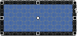
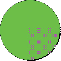
3. Draw a marquee over the object in such a way that you take up one-quarter of the object with the marquee (see
Figure 3.12).
4. Press the Delete key to remove the section.
5. Draw a rectangle primitive using any stroke and fill color and other settings you like.
6. Draw an oval primitive using any stroke and fill color and other settings you like.
7. Press V to change to the Selection tool.
8. Move the new oval on top of the rectangle.
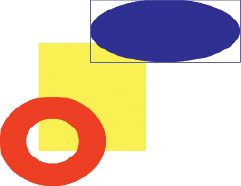
9. Note that the oval remains on top of the rectangle, obscuring it.
10. Right-click the oval and select Arrange
Send To Back from the context menu or select Modify
Arrange
Send To Back from the main menu. The oval moves to the back while the rectangle comes to the front.
Summing Up Basic Drawing
In summary, the basic drawing technique works this way:
1. Visualize the drawing you want to create as a series of rectangles, ovals, shapes and lines.
2. Use Merge Drawing techniques to carve out curves and other features you need.
3. Use Object Drawing to put objects on the stage that you do not want to merge with other shapes.
4. Use Primitive shapes for more shapes you think you may want to modify later.
5. Use the technique of breaking apart and drawing a marquee around the parts of the shape you want to delete.
6. Instead of drawing a marquee around objects, you can optionally use the Lasso tool (hotkey L) to select unusual or complex parts of a shape you want to delete. The Lasso tool allows you to perform more complex marquee operations around objects.
Drawing Polygonal or Star Shapes with the PolyStar Tool
The PolyStar tool is useful for creating geometries with more than four sides and for creating stars. You can find it within the same grouping as the shape and primitive shape tools. Follow these steps:
1. From the basic shapes button drop-down, select the PolyStar tool

.
2. Select a fill and stroke color.
3. Click and drag the shape, noting that the default shape is a pentagon.
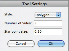
4. Click the options button, and the Polystar tool dialog box opens (see
Figure 3.13).
5. In the Style drop-down, select star.
6. Leave the number of sides at 5.
7. Leave the star point size at 0.5.
8. Click and drag a star on the stage.
9. Select the Subselection tool (hotkey A) and then click the star you just created.
10. Click and drag any corner of the star to resize it.
11. Click the Free Transform tool (hotkey Q) and readjust the star’s size.
12. Press the V key to activate the Selection tool and move the star anywhere you like on the stage.
13. Move the star onto the pasteboard. Note that objects on the pasteboard do not show up when you play the movie with Ctrl+Enter (Command+Enter on the Mac).
Making Artsy Shapes with the Deco Tool
One of the coolest tools in Flash is the Deco tool  . It provides you with elaborate, colorful shapes that you can paint on the stage, as you see in the following exercise:
1. Make sure the Selection tool is active by pressing V on the keyboard.
2. Drag a marquee to encase all current objects on the stage.
3. Press the Delete key to delete all current objects.
4. Press U on the keyboard to select the Deco tool.
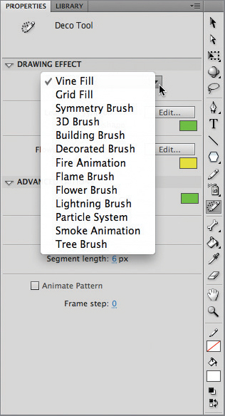
5. Click the drop-down in the Drawing Effect section to reveal the various effects available with the Deco tool (see
Figure 3.14). Note that there are many different customization options available, depending on the drawing effect you choose. You can be quite elaborate when using this tool.
The fill operation will continue until you click again to stop it. You can rapidly fill up the stage with a fill if you’re not aware of this. If you add too much you can seriously increase the size of your final file and thus the CPU time needed to put it on the screen. Go easy!
6. Select Vine Fill.
7. Click anywhere on the stage. Flash begins to draw the Vine Fill; click when you want it to stop.
8. Press Ctrl+Z to undo the Vine Fill operation.
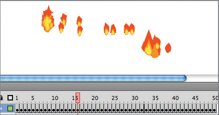
9. With the Deco tool selected, select the Fire animation drawing effect.
10. Click and drag on the stage to paint with some Fire (see
Figure 3.15).
11. Click again to stop.
Observe that Flash creates many new frames to accommodate the fire animation. This will have implications when you want to create other layers with other assets on them. I’ll discuss this in more detail in Chapter 4, “Getting Started with the Timeline,” and Chapter 7, “Developing Simple Flash Animations,” when I start talking about placing art assets on different layers and frames.
12. Press the Enter key to watch Flash play the fire animation. Flash stops playing the animation when it hits the last frame. If you play the movie with Ctrl+Enter (Command+Enter on the Mac), the fire animation will play repeatedly until you close the movie. In Chapter 7 and Chapter 13, “Working with ActionScript,” you’ll learn more about how to use ActionScript to stop frames from playing over and over in a movie.
Drawing Other Shapes
Flash includes several other tools you’ll want to know about to round out your drawing capabilities:
3D tools The 3D Rotation

and 3D Translation

tools (hotkeys W and G, respectively) can be used to apply 3D-like effects to 2D images:
1. Press Ctrl+Z to undo the Fire animation from the previous exercise.
2. Press R to select the Rectangle tool.
3. Select a fill and stroke color.
4. Note that the corner radii setting from any previous Rectangle work you have done is still there. You can set the setting back to 0 if you desire.
5. Draw a rectangle on the stage.
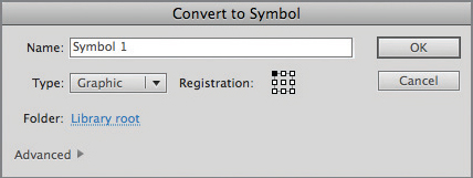
6. Right-click the rectangle and select Convert To Symbol from the context menu. The Convert To Symbol dialog appears (see
Figure 3.16).
7. From the Type drop-down, select Movie Clip.
8. In the Name box, type mc3D (more on this naming convention in Chapter 6).
9. Click OK. The Convert To Symbol dialog disappears.
10. Note that the rectangle looks a little different than it did before. This is because Flash has converted the rectangle to something called a symbol. The symbol’s type is movie clip. More on this in Chapter 6.
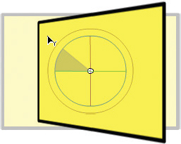
11. Click the 3D Rotation tool. The rectangle now has three rings of different colors around it. The red circle rotates the object in the x-axis, the green circle in the y-axis, and the blue in the z-axis. An easy way to remember this order is red, green, blue = RGB = XYZ.
12. Click and drag the blue circle to rotate the object on the z-axis (see
Figure 3.17).
13. Press the G key to switch to the 3D Translation tool.
When you see the word translate used with graphics programs, think “move.”
14. The rectangle now has two arrows on it. The convention used for the colors is the same as with the rotation tool (for example, RGB = XYZ).
15. Click one of the arrows and drag it to move the rectangle.
The Pen tool You can find four tools lurking under the Pen tool button on the Tools panel

. The Pen tool (hotkey P) is used just as its name implies—to draw shapes as though you have a pen in your hand. If you own a digital tablet, you’ll find that the Pen tool works just fine with the device.
More interesting are the Add Anchor Point, Delete Anchor Point, and Convert Anchor Point (hotkeys =, -, and C, respectively) tools. Recall that the Subselection tool allows you to manipulate extra points you add to your drawing. How do those extra points get there? Selecting the Add Anchor Point tool, you simply click the area of the shape where you want to add an anchor point and there it is, ready to be manipulated with the Subselection tool. It does not matter whether the shape has a stroke; you can add points on either the stroke or the fill, although they’re added on the edge of a shape, not anywhere inside it. You can use Delete Anchor Point to remove an anchor, as shown in this exercise:
1. Delete all objects from the stage.
2. Press the R key to activate the Rectangle tool. (It doesn’t matter if Merge or Object Drawing mode is selected.)
3. Select a fill and stroke color.
4. Draw a rectangle on the stage.
5. Press the equal sign (=) on the keyboard, activating the Add Anchor Point tool

.
6. Click anywhere on the stroke of the rectangle. Flash adds an anchor point.
7. Press A to enable the Subselection tool.
8. Click and drag any of the anchor points in or out to modify the rectangle’s shape.
9. Press the minus sign key (−) to activate the Delete Anchor Point tool.
10. Click one of the anchor points you added previously. If you delete an anchor point that you used to alter the shape of the object, the object returns to its original state at that position.
11. Press the C key to activate the Convert Anchor Point tool

.
12. Click and drag on an anchor point you added previously. Flash provides
Bézier curves at the anchor point and the ability to create a curved surface at that location (see
Figure 3.18).
What’s a Bez-ee-eh?
In digital tools such as Flash, Bézier (pronounced “bez-ee-eh”) curves provide a handle that allows you to change the height of a curve’s slope on either side and also allows you to enlarge the curve or skew the curve to the right or left. If you click either end of the line representing the Bézier curve, just that section of the curve will raise or lower. If you click and drag in the middle, you can raise or lower both sides of the curve uniformly, and then you can skew the curve to one side or the other. At first you may find Bézier curves tricky to work with, but once you get the hang of them, you’ll be impressed with the depth of creativity you can bring to an object with them.
Text tool I will go into more detail about the Text tool (hotkey T) in Chapter 5, “Adding Flash Text and Fonts to Your Creations.”
Line tool The Line tool (hotkey N) does exactly as its name implies. Select the Line tool; assign a stroke color, width, and line style; and then begin clicking and dragging. When you let up on the mouse, Flash draws the line for you. The Line tool stays active, and you’re ready to draw the next line, as shown in the following exercise:
Using Ctrl+A is a quick way of quickly selecting all objects.
1. Press Ctrl+A to select all objects on the stage and then delete them.
2. Press the N key to select the Line tool.
3. Draw a series of lines that connect together, like a square for example. Zoom the screen size if needed so you can make sure the lines connect.
4. Flash recognizes that the shape is completely enclosed.
5. Press K to select the Paint Bucket tool

.
6. Select a fill color from the Color Picker.
7. Click inside the square to fill it with the color you selected (see
Figure 3.19).
Using the above technique, you can create an unusual shape not easily sculpted with the basic shape tools and fill it with a color of your choice.
Pencil tool Use the Pencil tool to draw lines and shapes. When you activate the Pencil tool, a shape tool becomes available in bottom of the tool bar. Use it to control the smoothness of the lines created with the Pencil tool.
Paint Bucket and Ink Bottle tools I covered the Paint Bucket tool earlier. The Ink Bottle tool

resides within the same tool grouping as the Paint Bucket tool. Using the S hotkey, you can use the Ink Bottle tool to change the color of a stroke:
1. Using the Selection tool, select one segment of the line you drew in the previous exercise.
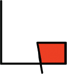
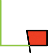
2. Press S to activate the Ink Bottle tool.
3. Pick a new stroke color.
4. The stroke you selected is changed to the new color.
Simply select the tool, pick a color, and then click a stroke in which you want to change the color. If you experiment with this, you’ll be surprised which strokes Flash considers to be contiguous line segments. Figure 3.20 shows the line drawing I created earlier and then modified with the Ink Bottle tool and a new stroke color. Even though the line that’s half green and half black was a continuous black line when I first drew it, you can tell that Flash considers the four lines used to create the square filled with red to now be combined into a separate line segment. Further, if I click the four lines making up the square, Flash considers them to be one contiguous line and fills them all in with the new color.
Bone and Bind tools The Bone tool (hotkey M)

is used to put various drawn segments together to animate them. The Bind tool (hotkey M)

is used to modify segments already connected together using the Bone tool. We’ll talk about the Bone tool in more detail in Chapter 10, “Creating Characters with Inverse Kinematics (IK).”
Eyedropper tool The 16th tool down from the top (hotkey I)

is used to sample the color of an object (whether vector drawn or photo image) to use as a fill color.
Eraser tool The Eraser tool (hotkey E)

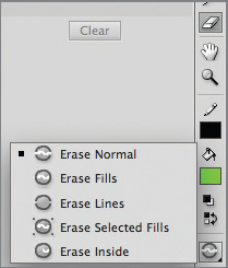
is used to erase drawings you’ve put on the stage. In some cases the bottom half of the Tools panel changes based upon the tool that has been selected up above: this is the case with the Eraser tool. Follow the steps below to learn more about using the Eraser tool.
1. Press E to activate the Eraser tool.
2. Note that as soon as the Eraser tool is selected, the bottom half of the Tools panel has three new entries on it that directly pertain to eraser operations (see
Figure 3.21).
3. Click the Erase Mode button (third from bottom of the Tools panel) and make sure it is set to Erase Lines.
4. Select a fairly large eraser size.
5. Click and drag across part of the lines you created to erase them.
6. Click the Erase Mode button and set it to Erase Fills.
7. Click anywhere in the fill you created with the Paint Bucket tool.
8. Observe how much of the fill is removed with this setting.
9. Without altering the other eraser settings, click the Faucet tool button (second from bottom).
10. Click the fill again, this time noting that it is completely erased.
Hand tool The Hand tool (hotkey H)

is used to move the stage one way or another—called
panning:
1. Click the Hand tool to activate it.
2. The mouse cursor changes to a hand shape.
3. Click and hold on the stage, moving the mouse left, right, up, and down to see how the Hand tool allows panning.
Zoom tool The Zoom tool (hotkey Z)

is used to enlarge or reduce the stage:
1. Press Z to activate the Zoom tool.
2. The mouse cursor changes to a magnifying glass with a plus sign.
3. Click an object you’d like to enlarge.
4. Flash zooms into the area and enlarges it for you.
5. Repeat the zoom maneuver.
6. Flash enlarges the view yet again.
7. Hold down the Alt key (Option key on the Mac). The mouse cursor changes to a magnifying glass with a minus sign.
8. Click the scene. Flash zooms out of the scene with each click of the Zoom tool.
Working with Color in Flash
There are some test questions that revolve around using the Color and Swatches panels in Flash, and there are also design issues that revolve around your selection of colors.
Using kuler
Adobe Systems Inc. has a website dedicated to color swatches. The site’s name is kuler (lowercase), and it can be accessed at http://kuler.adobe.com/#. Think of kuler as a social site where registrants are able to upload color swatches that have worked for them in projects.
Because many people have a problem with color matching when it comes to design decisions, kuler is a fantastic place to go if you’re looking for color matches. Follow these steps:
1. Open your favorite web browser and navigate to the kuler site.
2. Click the Register link and create a kuler account for yourself. If you already have an Adobe account, your logon will work on this site as well. You do need to have a valid account to be able to download color swatches.
3. In the search box, type a keyword for a color swatch you’d like to look for. For example, typing “Halloween” returns a variety of color swatches.
4. As you browse through the list of swatches your keyword returned, select one by clicking on its name.
5. Click the color swatch, noting that it takes up the full screen.
6. Click the swatch again to return it back to normal.
7. To the right of the swatch’s name you’ll see a series of three buttons

. Click the middle button, “Download this theme as an Adobe Swatch Exchange file.”
8. When presented with the Explorer box prompting you for the location where you will save your file, create a new folder called kuler Swatches and save the file inside this folder, using the same name as the original file.
9. In Flash, click the Swatches panel button

.
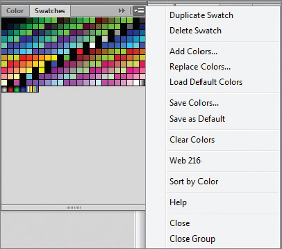
10. In the upper-right corner of the Swatches panel is a drop-down that, when clicked, brings up a context menu of options you can choose (see
Figure 3.22). Choose Add Colors.
11. Navigate to the folder where you downloaded your kuler swatch.
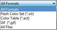
12. In the All Formats drop-down, select All Files. Your kuler swatch will appear.
13. Select your kuler swatch, noting that all of the colors associated with the swatch appear in your swatches list (see
Figure 3.23).
Saving a Color Set
Suppose you have a set of colors you’ve accumulated that you’d like to save in the Swatches panels so you can use them again in a future project. Using the same Swatches drop-down mentioned earlier, you can choose Select Colors and then save the current color set to your computer for future use, giving it a meaningful name. You load saved color sets the same way that you loaded your kuler file.
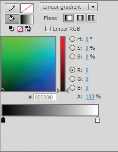
Working with Color Gradients
A color gradient is a representation of several colors that fade from one color into another. Gradients are useful for bringing more of a 3D-like feel to art assets on the screen. There are two types of gradients: Linear (in a line) and Radial (in a circle). Let’s use an exercise to create one of each:
1. Open a new ActionScript 3.0 document.
2. Click the Color panel button

.
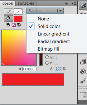
3. In the color type drop-down (see
Figure 3.24), select Linear Gradient.
4. A new black and white Linear gradient appears (see
Figure 3.25).
5. On the bottom line of the gradient, somewhere in the middle of the line, left-click with your mouse. A new gradient point appears.
6. Change this point’s color to red by keying (r: 255, g: 0, b: 0) in the RGB boxes, or type #FF0000 in the hex box.
7. Exit the color panel.
8. Select the rectangle tool with R or the oval tool with O. Note that your new gradient color is automatically the active color.
9. Draw a rectangle or oval on the stage.
10. Within the free transform tools there is a tool called the Gradient Transform tool (hotkey F). Activate this tool.
11. Click the rectangle or oval you just drew. Several gradient tool options are now active (see
Figure 3.26).
12. Move the white dot in the center to the right or left. Note that the spread of the gradient colors changes.
13. Click the circle icon in the Gradient Transform tool and rotate the gradient a quarter of a turn upward. Note that the gradient color blends shift to show an upward turn.
14. Click the box with an arrow icon and slide it to the right. Note that the gradient color blend spreads out farther. There is more distance between each of the primary colors in the gradient and more calculation of color change between them.
15. Repeat these steps, this time creating a radial gradient instead.
A New Way of Assigning Colors
HSB is another way of thinking about object colors. “H” stands for hue, “S” saturation, and “B” blend. “H” is the color you want, “S” is the amount of that color you want, and “B” is the blend of white and black you’ll add to the color to create derivations of that color. This coloring technique is quickly becoming the new standard and I recommend you learn more about it as you move forward. I recommend that you Google “HSLA” for more information.
You can have multiple color points  in a gradient. Click a color point to activate it so you can change its color. The triangle at the top of the color point will change from white to black, and you’ll see its current color in the color spectrum box above the gradient. You can also slide a color point from side to side to make minor adjustments to the color spread. Click and drag a color point off of the gradient to remove it.
Use gradients as a way of showing light shining on a material in an object or the shadowing on an object. For example, suppose you want to have some shiny aluminum material on an object in your rich media content. Use a silver gradient, rotating the gradient in such a way that the lightest part of it points to an (imaginary) light source.
The Essentials and Beyond
Adobe has crammed a lot of functionality into the Tools panel, overloading many of the buttons with several choices. Some buttons you’ll use routinely; others you will probably seldom visit. By using the tools at your disposal, coupling them with great color choices—especially color gradients—and using elements such as the Bone and 3D tools, you have tremendous drawing capabilities. In this exercise, you’ll create a star-filled background.
Additional Exercise
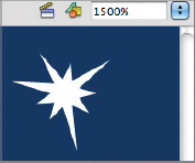
- Start Flash and create a new ActionScript 3.0 document.
- Change the stage color to a dark nighttime sky color.
- Maximize the stage size using an extremely large number (1000–1500% or greater).
- Create one relatively small star using the PolyStar tool—adjusting the points to your liking.
- Draw a marquee around the object, right-click the object, and select Convert To Symbol to turn the object into a graphic, giving it any name you like.
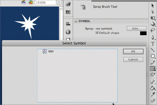
- Using the Spray Brush tool, in the Symbol section of the Spray Brush’s properties, select the star graphic you just created.
- Make any spacing and size adjustments you desire.
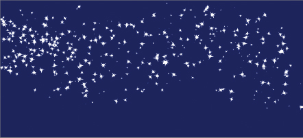
- With the Spray Brush selected, spray to cover your background with stars.
Answer for Additional Exercise