Chapter 2. Use Cases
Engineering is the application of science and mathematics by which the properties of matter and the sources of energy in nature are made useful to people.
—Webster’s New Collegiate Dictionary [Webster 1999]
What’s in this chapter?
This chapter discusses the basic format and protocol for finding and creating use cases. It also discusses and defines the basic UML notation for diagraming the use case model.
In the last chapter, we showed how external entities called actors play a role in the development of a system. The next element in the development of our model is the use case, the central modeling construct of the process. A use case describes the way a system is employed by its actors to achieve their goals. It is quite literally “the act.” Formally, a use case is
a description of a set of sequences of actions, including variants, that a system performs that yield an observable result of value to an actor. [Booch 1999]
A use case describes a single goal and all the possible things that can happen as the user attempts to reach the goal. Regardless of the type of complex system being described by the use cases—business, business process, software system, framework, or component library—the definition is the same.
Finding Use Cases
To understand how we find use cases, let’s start with the loan processing use case diagram that was begun in the introduction to Part 1. In the first step we defined the system boundary (denoted by a rectangle) for a loan processing system. Now we add the actors (denoted by stick figures) outside the system boundary (Figure 2-1) and begin to fill in the system boundary with use cases to model the functionality of the system.
Figure 2-1. Partial use case diagram for the loan processing system

To find the use cases for a given system, we must examine the goals of the system [Cockburn 1997a]. The goals of a loan processing system might include the following.
• Apply for loan. The applicant submits the information necessary to apply for a loan. The information is checked for completeness by the system.
• Check status of loan. The applicant may query the system for any status changes in the loan as it proceeds through the acceptance process.
• Submit additional loan information. If the loan request requires additional information, such as an explanation of a problem in a credit record, the applicant must provide the information for the loan process to proceed.
• Accept loan. When the loan is approved, the applicant must agree to all conditions under which the loan is issued.
Enumerating goals helps us find use cases. Each general goal that yields observable value corresponds to a use case (Figure 2-2).
Figure 2-2. Loan processing use case diagram with use cases

Use cases provide observable (sometimes called measurable) value to an actor. Therefore, use cases always describe an interaction between a system and at least one actor. This relationship between an actor and the use case is called an association. When an actor is associated with a use case, it is said that the actor communicates with the use case.
Associations may be bidirectional or unidirectional. Unidirectional associations are represented by a line from the initiator of the communication with an arrowhead printing in the direction of initiation [Quatrani 2000]. An association may reflect behavior of the actor or of the use case. When an actor initiates the communication with a use case, it is called an initiator (Chapter 1). However, use cases can initiate communications with actors, as well.
A good example of a unidirectional association would be the association between the applicant and the “Apply for loan” use case (Figure 2-3). The applicant always initiates the communication, so the association between applicant and the “Apply for loan” use case is unidirectional with the arrow pointing to the use case. However, if the system required functionality to notify an applicant of the need for additional loan information (such as the reason for a credit record blemish), the “Request additional loan information” (not shown in Figure 2-2) use case might initiate the communication.
Figure 2-3. Unidirectional associations between an actor and use cases

Understanding who initiates communications can be helpful when starting to write a use case. Most use case modeling tools, such as Rational Rose, support unidirectional associations. Still, many use case modelers choose not to use unidirectional associations because it is often evident from the use case who the initiator is.
A well-formed use case model must show associations (either unidirectional or bidirectional) between each use case and some actor. Although we will see exceptions when we refactor the use case model, use cases are usually triggered by some event that is initiated by an actor. Therefore, if unidirectional associations are used, most use case models should have a unidirectional association originating from some actor to each use case. Use cases that do not communicate with at least one actor are suspect since every use case, by definition, provides value to an actor.
Associations between actors and use cases logically lead to a discussion of interfaces. Interfaces are a vital part of any complex system. An interface is the protocol and medium by which actors interact with a complex system. In business systems, call centers may provide billing information or technical support via the telephone. In software systems, there are interfaces to the user and to other systems. In component systems, interfaces may be CORBA IDL, the definition of interface class methods, or framework hotspots [Pree 1995].
Each association contributes to an overall interface between the system and its actors. An interface is the composite of the elements necessary to facilitate the interactions between an actor and the system. Interfaces should be documented in interface specifications (see Chapters 5 and 17).
Describing Use Cases
Once we have identified the goals of the system and placed them inside the system boundary, we must describe how we intend to reach each goal with our system. A use case is much more than an oval in a use case diagram. A use case is a narrative representation of the behavior of the system. A use case is composed of a name and a description (often called the body of the use case) of the many ways to achieve the goal.
We named our use cases in the last section when we enumerated the goals of our system. The name should describe the desired goal. For example, “Rent video” would be a logical candidate for the name of a use case where the video clerk rents a video to a customer. Naming use cases will be described in more detail in Chapter 7.
Once a use case is named, the description must be written in narrative text. However, simply writing a use case without an outline can make the use case difficult to understand and change, especially when it describes a system of substance. To permit any stakeholder to understand the use case quickly, the body of the use case must be carefully structured.
The use case structure divides the use case body into logical pieces (Figure 2-4). Structure ensures that use cases are consistent across the entire system by showing writers what details to consider when writing a use case. Structure also helps the readers find the element of the use case that they are looking for.

There are probably as many variations of use case structure as there are organizations doing use case modeling. The requirements for what should be included in a use case may be outlined in the development case (see Chapter 19) and captured in a use case template (see Chapter 8). A use case template defines the structure of the use case body for all use case developers on a given project. A use case template for all projects may be difficult to standardize, but most normally include at a minimum the following:
• Actors. Description of the actors involved in the use case.
• Preconditions. Constraints on the state of the system before the use case can be triggered.
• Flow of events. Activities that occur as the actors and system attempt to reach a goal. The activities can include the interactions between system and user. They may also include transactions the system performs in response to or to support these interactions, and any initial setup steps that an actor or system must perform prior to an interaction but that directly affect the interaction.
• Postconditions. Constraints on the state of the system after the use case has successfully completed.
Preconditions and postconditions describe the state of the system or, more appropriately, the state of the elements of the system, before and after a use case has run its course. A use case cannot be started until its preconditions are met. For example, the loan must be approved before the applicant may accept (sign for) the loan. Some use cases may not have constraints (and thus have no preconditions) on their ability to be started. The “Apply for loan” use case may not have any restrictions on its ability to be started.
A use case that has run its course may have postconditions, certain things that are always true if the use case was successful. For example, once an applicant accepts a loan, the applicant is now a borrower and must pay back the loan. A new loan has been created and money moves from the lending institution to the borrower. Other use cases may not change the state of the system and so have no postconditions. An example of this form of use case is “Check loan status.”
The flow of events describes all of the many ways that a desired goal may be reached (or in some cases, fail to be reached). It can take many forms. In free-flowing text form, the goals are described in a narrative. Free-flowing text is one of the two most popular forms; the other popular method of describing use cases is the step method, an annotated form. In the step method, each step toward the goal is consecutively numbered.
The aim of the flow of events is to describe all the ways a system may behave as an actor attempts to reach a goal. On route to the goal, there will presumably be several decision points (Figure 2-5). A decision point is an area where the system, or in some cases the actor, must decide if it is proceeding along the expected path to the desired goal. The expected path of “Rent video” involves moving the video copy off the shelf (the inventory), validating the membership, and receiving money equal to or greater than the rental cost. At these decision points, the system responds as expected and the experience for the video clerk (and hopefully the customer) is routine.
Figure 2-5. Decision points described in the body of a use case

But what happens when the video appears to be already checked out, the membership has late fees on it, or the credit card is denied? These exceptions or alternate paths must also be captured in the use case. In some cases, these contingencies can be resolved and the goal may be achieved. In other cases, an unsuccessful outcome may result.
Refactoring the Use Case Model
A system may be defined as the sum of its use cases. When attempting to capture a complete set of behavior, a use case model can become overly complex because it contains redundancy; that is, parts of two or more use cases may describe the same functionality. Extend and include relationships are a way of refactoring, or structuring, the use case model to deal with redundancy. These relationships help eliminate commonality across use cases.
An extend relationship (Figure 2-6) allows a use case to be “extended” with additional behavior and variations. An extend relationship is useful when one use case has all the behaviors of another. For example, a three-way telephone call requires that a basic telephone call be made first. The call originator must dial the first party and then dial the second party. Therefore, the “Originate three-way call” use case extends the “Originate basic call” use case.
Figure 2-6. Extend relationship between use cases

A use case can have many extend relationships. The extending use case can also choose when to use the functionality of the use case that it extends. The extend relationship between use cases is represented by a directed line from the use case providing the extension to the extended use case.
An include relationship (Figure 2-7) allows a use case to access a set of behaviors defined in another use case. It is a good mechanism for capturing and representing common behaviors used by multiple use cases. This functionality can be factored into abstract use cases included in use cases. An abstract use case is simply a reusable piece of functionality. Abstract use cases have the unique characteristic that they do not need to be directly associated with an actor.
Figure 2-7. Include relationship between use cases

One of the most common abstract use cases is “Authorize user” (also known as “Login”). Since many systems require a user ID and password (or some other form of authorization) to enter the system, this use case is found in many use case models. The include relationship between use cases is shown by a directed line from the use case that is using the abstract use case.
Include and extend relationships can be confusing to new use case developers. Many use case experts recommend avoiding discussion of these refactoring techniques until a use case development group is very comfortable writing use cases. Writing good use cases can be tricky enough for those new to use case modeling; refactoring cases can be downright frustrating. We discuss this confusion in more detail in Chapter 10.
As demonstrated in Chapter 1, actors may share the behaviors of an abstract actor. This relationship is known as generalization (Figure 2-8). Generalization is especially common when one actor may become another (such as an applicant becoming a borrower after a loan is made). In the use case diagram, inheriting behavior is depicted by the type of arrow shown in Figure 2-9.
Figure 2-8. Applicant and borrower inherit from bank customer
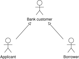
Figure 2-9. Development priorities for the loan processing system

Extending the UML Use Case Process
All of the fundamentals we have described thus far are part of the Unified Modeling Language specification. However, advanced use case modeling enhances the basic use case process and its symbol language to describe elements necessary when building complex systems (Table 2-1). We describe two forms of the use case beyond the canonical form found in the UML: prioritized use cases and change cases.
Table 2-1. Elements of the UML and advanced use case modeling

Prioritized Use Cases
Basic use cases are prioritized to define the order in which functionality is needed (Figure 2-9). Prioritized use cases allow the definition, development, and/or deployment phases of the engineering process to proceed in an orderly fashion. For example, the deployment of the automation of a business system may be planned to be carried out in phases. Prioritized use cases allow recognition of the aspects of the system that must come first and those that can be delayed.
A prioritized use case is represented by the regular use case oval with a number inside (see Table 2-1). The lower-priority use cases, indicated by a larger number, may be delayed in its definition, development, or deployment.
Priorities and the properties that lead to prioritization are described in Chapters 4, 15, and 19.
Change Cases
Another form of use case outside the canonical form is used to describe potential changes. Change cases document potential future behavior of the system [Ecklund 1996]—behavior that is outside the scope of the current project, perhaps to keep the scope of the project manageable, but that may have to be incorporated into the system in the future without reengineering or designing the system.
A well-known axiom of system development is that the architecture of systems tends to be more resilient to change if the change is anticipated when the architecture is created. It is also well known that some change in systems can be anticipated. Change cases allow us to anticipate future requirements and build a better system architecture.
Change cases are represented by an oval with a triangle (delta) inside (Figure 2-10). The black triangle lets everyone know immediately that this functionality is outside the scope of the current system. Because change cases are a special form of prioritized use case, some developers use the symbol of a prioritized use case (see Table 2-1) with a special priority signifying that the use case is beyond the scope of the project. Regardless of how they are symbolized, they should be clearly differentiated so that they do not become a distraction. This form of use case is described in more detail in Chapter 17.
Figure 2-10. Potential future functionality for the loan processing system

Organizing the Use Case Model
Large use case models may result in information overload. Even the use case diagrams may not allow stakeholders to quickly understand which use cases they need to read. Hence use cases must be organized into logical groupings. These groupings are called packages. A package looks like a folder in a use case diagram and contains use cases (Figure 2-11). A package name should reflect the properties common to its contents. The many ways to organize the use cases in a use case model are discussed in Chapter 15.
Figure 2-11. Package containing the loan application functionality

Another Approach to Building a Use Case Model
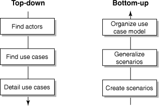
The steps we have just described represent a top-down approach to building a use case model. The top-down approach assumes that you understand enough about your system to provide general descriptions. A bottom-up approach can also be used to build use case models [Regnell 1996]. A use case model built from the bottom up starts with the specifics of the problem and generalizes them to create use cases (Figure 2-12).
Figure 2-12. Top-down and bottom-up approaches to use case modeling
To understand how the bottom-up approach works, we need to understand the difference between a scenario and a use case. The use case contains all the paths, both successful and unsuccessful, in our attempt to reach a goal. A scenario is one of these paths with specific information included in it [UML 1999]. For example, Tom attempts to place a voice call to Sally, who is already talking to someone else, so Tom receives treatment (a busy signal). This example path is a scenario in the use case “Originate basic call.”
Scenarios can be used to structure use cases. A popular technique for creating the flow of events description is to start with the “sunny day” or “best way” scenario—that is, what happens when everything goes perfectly. General terms are used to describe this initial flow; specific details (such as “Tom” and “Sally”) are not used. Creating this scenario can be an easy way to get started when writing use cases for the first time.
Of course, there are usually a large number of potential scenarios for a given goal. Some will yield successful outcomes, others will not. Other successful scenarios will deviate at some point from the “best way” scenario. The deviations can be recorded as substeps. If we collect a group of scenarios that address the same goal and record them in a general form, thus capturing a complete class of scenarios, we create use cases. This is the second step in the bottom-up process.
Finally, we can generalize the roles of the participants to create actors. Once we draw the associations between the actors and the use cases, we have completed the last step in the bottom-up approach to creating use case models. All the optional steps, such as prioritizing, adding future requirements, refactoring, and organizing the model, can then be added.
Running through scenarios allows us to determine the completeness of use cases. Simply reverse the process of recording scenarios and use them to test use cases. Since the use case must contain all the goals of our system, missing scenarios means incomplete use cases. The point is that we can use scenarios to create use cases or validate them. Using scenarios in this manner ensures that the use case covers all of the possible attempts to reach a goal.
Conclusion
The extended use case modeling process is useful for describing very simple systems. However, the complexities of most of today’s software systems require more than the simple steps of the fundamental process. These systems require an advanced use case modeling process.
In advanced use case modeling, each step of the extended use case modeling process is enhanced to provide a process framework that may be customized to fit the project; detail and steps are added to allow scalability.