Appendix B. Development Case for Advanced Use Case Modeling
Implementing a software development process is a complex task that should be carefully controlled.
—Phillipe Kruchten [Kruchten 1999]
What’s in this appendix?
This appendix defines a development case for those wishing to integrate the full advanced use case modeling process framework with the Unified Process. This development case contains only elements from advanced use case modeling and should be customized for your environment.
This appendix presents a development case for the advanced use case modeling process framework. This development case is geared toward a high-ceremony organization. In other words, it presents an outline of the entire process. Since advanced use case modeling is a process framework, this development case is meant to be tailored to fit the organization or project that uses it.
A process cannot be presented in isolation; it requires a software development life cycle and methodology. This process framework uses the software development life cycle described by Royce [1998] and the methodology described in this book. It also takes partial input from the Unified Process process framework described in Jacobson [1999]. To allow this document to stand on its own, we present a brief summary of Royce’s life cycle. Chances are, your development case (at least the part describing the capture of software requirements and architecture) will be smaller, as lifecycle information is usually contained in other documents.
Software Life Cycle
Royce’s software development life cycle forms the basis for the Unified Process [Jacobson 1999] and the Rational Unified Process. Both are iterative/incremental, use-case-driven and architecture-centric process frameworks for object-oriented development. Among other things, these frameworks provide practices, procedures, and guidelines for the entire object-oriented system development life cycle. Like advanced use case modeling, these process frameworks must be customized to fit the level of ceremony of your organization. Each framework is designed to be flexible and modifiable based on specific domain and project characteristics.
Royce’s life cycle divides the process of software development into four phases (Figure B-1). Briefly, a phase describes the activities and time between the major milestones. A milestone is a well-defined point where a well-defined set of objectives are met, artifacts are completed, and decisions are made on whether to move into the next phase.
• Inception. This phase is where the business case for the project is created and the project’s scope is outlined. In addition, success criteria, risk assessment, project estimates, and plans are created.
• Elaboration. During the elaboration phase, the problem is analyzed, a system architecture is created, and the description of most of the system requirements is documented. Usually, a part of the system can be created during this phase to validate the architecture by executing significant use cases.
• Construction. During the construction phase, the system is created iteratively and incrementally. If the previous phases were successful, much of the activity in this phase involves manufacturing the system.
• Transition. During the transition phase, the system is deployed to the user.
Figure B-1. Software system development life cycle [Royce 1998]

The major phases, process workflows, and their mapping across iterations are presented in the Figure B-2. Each iteration goes through different workflows with the focus being different at each phase.
Figure B-2. Iterations and workflow across rational unified process phases [Jacobson 1998]

• Business modeling. This workflow models the organization or business.
• Requirements. In this workflow, the use cases and requirements are discovered, documented, and modeled.
• Analysis and design. In this workflow, the system is further analyzed and designed.
• Implementation. In this workflow, the software is developed.
• Test. In this workflow, the test cases and procedures are created and executed.
• Deployment. In this workflow, the final system configuration is documented.
Use case modeling (at a system level) is primarily performed in the requirements workflow, which mainly crosses the inception and elaboration phases. If the use case modeling framework presented in this book was to be customized to fit within the Unified Process, the initial use case model would occur mainly in the inception phase and the remaining use case modeling would occur in the elaboration phase.
As a result, most of the activities of the advanced use case modeling process framework are found in the inception and elaboration phases of the life cycle. However, these activities drive the other phases. Because this book concentrates on the activities surrounding use case modeling, we do not include the details of the construction and transition phases.
Views
Workflows and phases provide two dimensions to the Unified Process; views provide a third. We have seen (in Chapter 16) how stakeholders may require many different ways of looking at a system. Artifacts must often be tailored to meet the needs of the stakeholders.
To address differing stakeholder needs, the Unified Process contains five views. A view allows us to isolate architectural details of a complex system in a manner much like the blueprint of a house [Kruchten 1995]. Isolating the details focuses the engineering effort on the needs of the stakeholders. Instead of attempting to describe the entire system in a single model, views allow us to specialize several models to meet the needs of the various stakeholders. The decisions of the stakeholders can then be captured in the models defined in each view.
Activities within a view may require information from other views. Elements from one view may depend on or be driven by those of another. Moreover, the views may need to be ordered so that the information shared between two or more views remains consistent. This dependency is depicted by an arrow in the view diagram. An exception to this rule occurs with the use case view that appears in all three view diagrams (one for each phase). The use case view has no arrows. Because use cases drive each view, the use case view is in the center of the diagram, signifying the dependence of the other views on it.
Advanced use case modeling defines the elements of the use case view. Since this view drives the others, the methodology also addresses the interfaces between the use case and other views. The methodology does not address all aspects of the other views. For these elements, we refer you to other methodologies that concentrate on these areas.
The architecture of software systems can also be decomposed into five views (Figure B-3). The names of the views are slightly different from those originally defined by Krutchen [Eriksson 1998]. The original names are given in parentheses.
Figure B-3. Five views of software system development

• Use case view. The use case view describes the functional requirements of the proposed software system. The functional requirements present the system’s functionality or what the system should do. This view describes how the system interacts with the other four views. The use case view also shows when a use case occurs relative to the rest of the system. Nonfunctional requirements and constraints on the system, such as performance, reliability, and availability, should be left out of the use case view.
• Logical view. This view shows the static and dynamic structure of the system (analysis and design). Functional requirements may be validated by checking them against the operation of the model.
• Component view (development view). This view depicts the component and subsystem organization.
• Concurrency view (process view). This view provides an understanding of the concurrent elements of the software system.
• Deployment view (physical view). The deployment view determines how the system maps to the physical layout (e.g., networked computers) of its environment.
Using the Development Case
This section is divided into lifecycle phases, tasks, views, activities, and steps. Lifecycle phases appear as bold headings. Tasks and views appear as subheadings. Activities appear as table titles; inputs, steps, and outputs appear as rows in the tables. Each input, step, or output may be categorized into one of three usage categories: mandatory, recommended, or suggested. These categories are described in the following table.

Advanced use case modeling can be used to define the requirements for a software system; other activities, such as analysis, design, and construction, are beyond the scope of this book. The process framework must be customized and placed within the larger software development life cycle that defines the various phases of the software development process. Many companies have defined their software development life cycle to meet the needs of software development in their industry or business. There are also commercially available processes that come with their own life cycle or definition of the development phases.
Inception Phase
The goal of the inception phase is to achieve a consensus on what is to be built, an understanding of the benefits it will bring, and an acceptance of the costs of building it. The activities of the inception phase center on the determination of these three things.
Task: Define the System Scope
This task defines what is to be built from an external point of view. It also defines who will interact with the new system.
Use Case View
Table B-1. Activity: Develop system concept

Table B-2. Activity: Identify stakeholders

Table B-3. Activity: Create initial system boundary

Table B-4. Activity: Review vision document
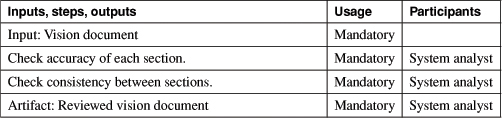
Table B-5. Activity: Identify actors

Table B-6. Activity: Discover initial use cases

Logical View
Table B-7. Activity: Create system glossary

Task: Create a Base Architecture
This task defines what is to be built from an internal point of view. It defines legacy systems with which the new system may be required to interact. Investigations into the technology and patterns necessary to frame such a system should be investigated.
Component View
Table B-8. Activity: Document “legacy” system interfaces

Table B-9. Activity: Create initial system architecture

Task: Determine System Feasibility (Macro Process)
This task defines an initial cost estimate for the proposed system. A cost/benefits analysis is also performed to determine the value of building it.
Table B-10. Activity: Determine system feasibility

Elaboration Phase
The purpose of the elaboration phase is develop a detailed requirements model, engineer a sound architectural foundation, and identify the tasks necessary to complete a project plan [Jacobson 1999].
Task: Define the System
This task develops the complete and detailed requirements model.
Use Case View
Table B-11. Activity: Develop base use case descriptions

Table B-12. Activity: Create use case relationships

Table B-13. Activity: Elaborate base use cases
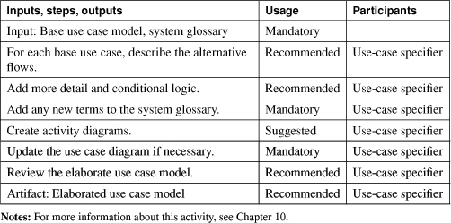
Table B-14. Activity: Develop scenarios

Task: Create the Architecture
Component View
Table B-15. Activity: Create new system interfaces

Table B-16. Activity: Create conceptual user interface specification

Table B-17. Activity: Create architectural prototype

Logical View
Table B-18. Activity: Create analysis object model

Concurrency View
Table B-19. Activity: Verify analysis object model

Task: Plan the Project (Macro Process)
Table B-20. Activity: Create project plan

Table B-21. Activity: Refine project plan

Summary of Artifacts
Artifacts are the intermediate outputs or deliverables of a process. Completion of part or all of an artifact represents a milestone in the project plan. This section gives a brief description of the deliverables of the advanced use case modeling process framework.
• Vision document. The vision (also commonly referred to as a system concept or concept of operation) document communicates the purpose of the application and the need for its existence [Leffingwell 2000]. The document contains a list of users and provides reasons for which product is needed. If applicable, the vision document positions the application with respect to others in the marketplace or business. Finally, and most important, the vision document contains the list of features required in the completed software application.
• Initial use case model. An initial use case model presents the high-level behaviors of the system and the system’s place in its business environment. A conceptual use case model provides a conceptual or overall picture of what the system will need to do. It provides a high-level model of the system for validation by key stakeholders before a more detailed use case model is created. The initial use case model contains the key initial use case descriptions, the major actors, and an initial mapping to high-level business objects. Initial use cases are similar to the user stories of Extreme Programming [Beck 1999].
Figure B-4. Software system development—requirements analysis artifacts

• Base system use case model. The base system use case model describes the uses of the proposed software system at a high level. Uses provide an orderly explanation of how users actually perform tasks with the system. The base use case model provides a cursory explanation of usage, omitting the finer details. The base application use case model also describes how the system interacts with its users and with other systems. This model is described in a combination of text and the Unified Modeling Language.
• Elaborated system use case model. The elaborated system use case model describes the uses of the proposed software application at a more detailed level than the base use case model. This finer level of detail achieves greater accuracy in capturing proposed uses of the system.
• System glossary. The system glossary is similar to the business glossary in its definition of domain entities. In fact, the business glossary can feed those business entities relevant to the proposed software development system directly into the application glossary. Like the business glossary, the system glossary provides a consistent or standard definition of the names of the elements of the software development system. The goal of the glossary is to provide a name and definition for various elements of the domain. The glossary is especially important if the domain is unfamiliar to the software development team.
• Software architecture document. The software architecture document outlines the subsystem layout and other architecturally important features of the software application. Software architecture must be balanced with software requirements and uses. This balance is especially critical in applications that have real-time, performance, or longevity constraints. The software architecture document should be created in parallel with the use case model on most systems.
• User interface specifications. The same type of interactions that foster the discovery of the uses of a software application foster user interface discussions. The user interface has been found to both aid and hinder the use of software to create automated or computer-aided solutions. The user interface specification allows user interfaces to be prototyped, captured, and approved by customers and users early in the software development life cycle. The use case model determines the places in the application where user interfaces will be required. User interface specifications may be created with a combination of word processing, screen capturing, and user interface prototyping tools.
• System interface specifications. System interface specifications define the interface to other systems. These other systems may exchange data with the proposed application. They may also provide services to or receive services from the application. Definition of the interface between the two systems sets expectations of the relationships between the two systems early in the development. Often, such specifications are used to provide interfaces between new and legacy systems or between two systems developed independently.