Chapter 16. Building User Interfaces
Until Doug Engelbart began his humanistic approach to computers less than thirty years ago, computer science was not noted for its contribution to the human spirit. That has changed. Designers today realize that our software is more than some static collection of dialog boxes and windows. It affects peoples’ lives in powerful and profound ways and we have a solemn responsibility to do everything possible to improve the quality of those lives.
—Bruce “TOG” Tognazzini [Tognazzini 1992]
What’s in this chapter?
This chapter presents a method for logical user interface design based on use cases. Use cases are broken down into transactions that are logically grouped together to form screens. Further decomposition may be performed to obtain reuse in the user interface.
A good user interface can make the difference between a software system that is completely intuitive in its use and one that leads to utter frustration. Understanding how to build an intuitive user interface (UI) requires knowledge of aesthetics, the physical elements of user interfaces (controls, widgets, windows, and so on), system content, and the system’s users. The best designers balance all these things to produce systems that are so easy to learn that the user only needs to read the documentation to understand the advanced features. Designers accomplish this by building an interface that corresponds to the user’s mental model of how the system should behave. However, designing the ultimate UI is perhaps more of an art than a science.
User interface design can be divided into two distinct phases: conceptual (sometimes called logical [Jacobson 1999]) and physical design. During conceptual user interface design, the focus is on the development of the content necessary to reflect the functionality of the system. Content is discovered and initial linkages between logical screens are proposed. The conceptual model reflects the needs of the system and the user in their interaction with one another. A use case model can help in the design of user interfaces based on content and, to some extent, information about the users. Use cases provide an excellent vehicle for deriving the conceptual user interface model.
Separating conceptual and physical user interface design is not new. Most projects concentrate strictly on the physical side. Conceptual design is often performed informally and as a side step through iteration of the physical design. Physical design deals with the aesthetics and selection of actual user interface components rather than with content. This emphasis on the physical side has been exacerbated by the ease of construction made possible through prototyping with user interface builders.
Since most user interface designers concentrate on physical design rather than conceptual design, logical aspects of the UI are often developed through iteration on the physical design until it “fits” the system. This iteration is a necessary part of the user interface development process, but refinement of the physical model should concentrate on usability and aesthetics rather than system functionality. System functionality should be explored in its own phase of user interface modeling, conceptual design. The conceptual design of a system should be explored before physical design is started.1
Conceptual User Interface Design
Before starting physical design, it is important to understand what information is needed by the user and the system, and at what time. This idea is the essence of conceptual design. Conceptual design
involves analyzing users’ needs in terms of the activities that need to be accomplished using a system and the objects and operations which a user has to accomplish the tasks. [Benyon 1999]
Use cases, system state diagrams, and the analysis object model can help determine what information the users need and when they need it. These three artifacts can serve as input to the conceptual design process.
Use cases and state diagrams help to provide a logical order to the conceptual design. We have seen in earlier chapters how these two models may be related. Use cases and the analysis object model can provide detail on what information will be needed from the user and the system to accomplish a task. System state diagrams can aid conceptual modeling by describing the state of various parts of the system and the events that may change the state. The analysis object model determines the relationships among objects in the system that contain, and therefore convey, important information.
Use cases naturally play the largest role in the way a conceptual user interface model is defined. Since use cases form the basis for the other two models, we feel use cases best serve as input to the conceptual model.
Creating Conceptual Models from Use Cases
As mentioned in Chapter 4, there is a danger of user interface decisions creeping into use case models. We strongly recommend that use cases remain independent of details regarding the presentation of information. Use cases should focus on uses of the system. The user interface should then be driven by these uses. The use case model should drive the creation of a user interface specification reflecting conceptual design. The physical design may be added to this interface specification later in addition to being captured in a user interface prototype.
We recommend five activities for describing the conceptual user interface model:
• Partition the use case model.
• Decompose the use cases into transactions.
• Determine the information content for each transaction.
• Establish logical screen order.
• Group and lay out logical screens.
Partitioning the Use Case Model
The first step in conceptual user interface design is to logically group use cases in the use case model specifically for user interface design. Two approaches to partitioning can be used, the work model approach and the user group approach. Either or both approaches can be used to start conceptual interface design as they both help to focus on the users as the primary concern.
Grouping use cases determines the potential paths that users will encounter as they proceed through the use case model. It also points out opportunities for reusing the logical user interface designs. When partitioning use cases in the use case model, only use cases with a human actor need to be considered. Separating the use cases that do not contribute to the user interface from the ones that do simplifies the overall user interface development process. It can also bring to the developer’s attention missing actors or missing use cases in the use case model. In the loan processing example (see Figure C-4), “Inquire about loan account status” does not have a human actor and so would not require user interface development. However, statistics may need to be recorded on the number of inquiries made. If this functionality were to be added to the system, it would be initiated by the loan manager and a new use case, “Determine inquiry statistics,” would be added to the use case model.
Users often expect to find tasks pertaining to activities they feel belong together near each other in the user interface. In the video store example, you might expect tasks related to video rentals to be grouped together in one set of screens and membership tasks grouped in another. The users would look for the function they wish to perform in the “area” that contains user interface representations of similar features. As was discussed in Chapter 15, partitioning the use case model in logical business groupings is called business function packaging. It is also referred to as the work model approach [Lif 1999] (Figure 16-1).
Figure 16-1. Work model approach to partitioning the video store use case model

Different classes of users often approach the system differently. One class of users might use certain functions of the system every day. Another class of users might use the system occasionally. A third class of users might administer the system. These classes of users usually correspond to one or more actors in the use case model. Therefore, a second way to partition the use case model is by grouping human actors or users (Figure 16-2). This approach is called the user group approach [Lee 1993].
Figure 16-2. User group approach to partitioning the loan process use case model
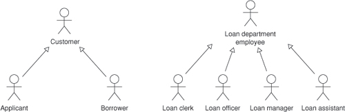
A differentiating factor in the user group approach is privileges. One group may have the ability to perform a certain set of functions that another group may not. There are also occasions when a group of even more privileged users is nested in a user group. A common example is management. A manager may be able to correct mistakes in addition to all the other activities of the user group. If there are several actors that represent different management roles, a new user group may be needed.
In the loan processing example, there are six actors: applicant, borrower, loan manager, loan officer, loan assistant, and loan clerk. We might create two abstract actors, loan department employee and customer, to divide these actors into two user categories or user groups (Figure 16-3). Each user group approaches the system differently. A customer will use the system with a lot less frequency than a loan department employee. A customer will have less domain experience as well. As a result, customers will tend to need a simpler user interface than the loan department employees. Customers also should be able to access limited information. They may look at only their own loan records, while the loan department employees may access the information of many customers in the course of their day.
Figure 16-3. Partial user group partitioning of the loan process use case model
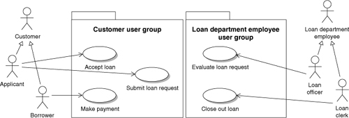
Once the user groups are created, the use case model is partitioned into packages representing the different groups. Some use cases may fall into more than one user group. When this happens, the two user groups need to be examined to see whether they should be combined. More likely, however, the two groups should remain separate; they may do the same sorts of things, but perhaps in slightly disparate ways. A use case may belong to more than one group.
Decomposing Use Cases into Transactions
Once the use case model is partitioned, the use cases themselves must be decomposed. To understand how use cases relate to the user interface, examine this first definition of a use case:
A sequence of transactions in a system whose task is to yield a result of measurable value to an individual actor of the system. [Jacobson 1995c]
The operative word in this definition is “transaction.” A transaction is the section of a use case initiated by an actor stimulus and completed when the use case awaits stimulus from an actor (not necessarily the same as the one that initiated it). Transactions allow us to partition use cases into smaller elements that allow us to determine the minimal information necessary at each decision point. Transactions help determine the minimal content as well as the sequencing.
This definition of a use case is completely consistent with the one given earlier in this book. We need not change our use case model to add the notion of transactions. Instead, we now identify transactions within our existing use case model. This can be done informally by circling the text in the flow of events of the use cases that describes a transaction. In higher-ceremony projects, a new use case model may be formed that formally divides a use case into its constituent transactions. Segmenting the use cases into a set of transactions is similar to segmenting use cases in other fashions (see Chapter 9).
Identifying transactions in use cases varies in difficulty, depending on the style used to describe the flow of events. For the purposes of user interfaces, we view transactions from the user point of view. Thus, transactions from this point of view are the reverse of that of the stystem. These transactions follow the pattern of (1) the system presents information, and (2) the actor does something. This pattern may be repeated many times until the use case is complete. Each instance of the pattern within a use case is a user interface transaction.
The final transaction of a scenario (path through a use case) does not follow this pattern. Usually, the system presents some final information indicating success or failure in obtaining the goal of the use case. In these transactions, there is an implicit user action that indicates that the user has acknowledged the final result, perhaps a closing of the last window, perhaps the clicking of an OK button, perhaps nothing at all but going to the next possible use case. For each of these “hanging” transactions, there should a method of moving to the next logical use case or set of use cases.
Transactions may also be identified in the “Alternative flows and exceptions” section of the use case description. Elements of this section usually fall into one of two categories. The first is an exception where something other than the normal flow occurs and status must be returned. These types of changes represent changes in the state of the system but may not warrant a new screen. In these cases, the exception belongs with the transaction that spawned it. The second is elaborate alternative flows that can yield transactions that follow the same pattern as the flow of events and that therefore should be identified as they were identified in the flow of events. In some use cases, the majority of the transactions may come from alternative flows.
Another area rich in transactions is the included and extension use cases. The transactions from these use cases will need to be evaluated when considering the later steps in the conceptual user interface design process. Included use cases, when involving human interaction, often contain the largest amount of reuse in the user interface. Extension use cases, when not considered in the user interface design, have the greatest potential for causing rework in the user interface.
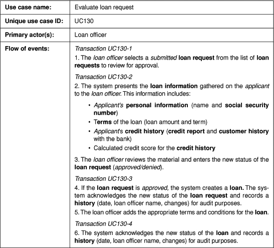
Each transaction needs to be labeled so that it can be referenced in the user interface specification (Figure 16-4). These labels provide forward traceability between the use case model and the interface specification. Since use cases are not linear (scenarios are), a linear numbering scheme will not work for labels. However, transactions may be named similar to the elements in the flow of events (see Chapter 8). In some cases, names within the flow of events may already correspond to transactions. This correspondence happens most often when the state approach to naming is used.
Figure 16-4. Identified transactions in the partial “Evaluate loan request” base use case
Determining Information Content
Once the transactions of a use case have been identified, the next step is to determine the information content of each one. This step is similar to what was described in Chapter 12, but the objects should be parsed from the information in each transaction rather than the information in each use case. The information should not be consolidated over the use case model. Rather, each business object should be recorded for its role within a transaction regardless of how many times it may be recorded over the use case model.
Transactions represent decision points in the use case. At a decision point, an actor must be presented with the information necessary to make the decision. This information is in the transaction itself or in prior transactions. After the decision is made, information acknowledging the decision is often returned to the actor. The goal of this step, “Determine information content,” is to identify the information.
Five classes of information may be found in transactions. The five classes reflect the types of information that may be found in object models. These types are conceptual rather than implementational.
• Attributes. Attributes are information elements that make up an object. Attributes are the most commonly displayed class. An example of an attribute is “name” in the “Evaluate loan request” use case. Attributes do not have to be actual data members; they may be derived from the information in the object. Since we have no design or implementation at this point, we cannot assume that these attributes will actually be implemented. For example, a point may have attributes “x,” “y,” “theta,” and “radius” to reflect Cartesian or polar coordinate representations. Although a point will be implemented using only one of these representations, the other representation is easily derived.
• Operations. Sometimes information must be calculated in the context of the use case rather than as a property of an object. This information is not a natural definer of the object, as an attribute would be. It is a genuine operation that must be performed in the context of the use case. An example of an operation is the credit score calculated from the credit history.
• Business objects. In user interface design, objects behave in two different ways. Complex objects represent categories of other information elements. These categories help focus the user on logically grouped information. For these objects, the information lies within the object, not at the object level. In the “Evaluate loan request” use case, the object “personal information” contains the attribute “name” and the object “social security number.” These objects (name and social security number) will contain the actual information displayed. Personnel information is a composite of other objects. The object “social security number” is a simple object. It behaves, as most simple objects do, like an attribute.
• State information. The notion of state in the proposed system has been illustrated throughout this book. State exists at many different levels in the system. System state is reflected through status messages. Objects may also have state. A loan request has at least three states defined by the “Evaluate loan request” use case: submitted, approved, and denied.
• Relationships between objects. Objects may be related to other objects in many ways. They may composed of other objects in a whole/part relationship called aggregation. They may be simply related to each other in a peer relationship. Relationships (or the lack of a relationship) may be as important as the information contained in the objects. For example, an applicant may or may not have a customer history with the bank. This relationship may not be contained in the customer object, but it must be displayed in the user interface.
These five classes of information must be discovered in the use case model. Missing information is often discovered in the process of mining these classes. This is especially true of attributes, which are commonly left out of the use case model. Conceptual user interface modeling is a good time to find this information, as it is often done very early in software development.
Creating the Transaction Information Model
Now that we have gathered all this information for each transaction, what do we intend to do with it? The answer is to create the transaction information model, which should be recorded in the user interface specification (Figure 16-5).
Figure 16-5. Transaction information model for transaction UC130-2
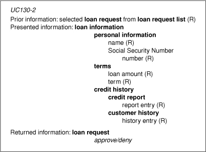
Recall that there are three areas that must be considered at each decision point in the use case. The first is information delivered to the user in a prior transaction and required by the user in the decision associated with the current transaction. This information is captured in the “Prior information” section. The “Presented information” section recognizes information elements delivered as part of the current transaction. Finally, information elements returned to the system are given in “Returned information.” This section lets the system know of the user’s decision.
In each area, we can have information from any of the five categories (attributes, operations, business objects, relationships, and state). As we traverse the object model, we often see layering. Layering occurs when elements are contained within other elements. This layering should be reflected in the model by indenting the contained elements. At the lowest layers (most indented elements), we should see attributes, operations, states, and relationships representing the minimal set of elements necessary for the user to make the decision. Elements other than those required to proceed to the next decision point should not be found in the model.
A business object often has many relationships. Therefore, relationships must be spelled out so that they can be understood. For example, the relationship between the loan request list and its loan requests is one of selection. Specifying the possible states in which the system or object may be placed must be stated helps to determine the physical user interface component to be used for its representation. It also allows potential validation at the user interface level.
There are several additions to the transaction information model. Objects may be created or destroyed as part of a transaction. A “C” or “D” in parentheses is placed to the right of the object when one of these two operations occurs to recognize a need to change the user interface to reflect new or no longer existing data. Similarly, attributes may be read only, read/write, or write only. When an attribute is read/write, the current value is displayed but may be changed by the user. An “R,” “R/W,” or “W” reflects the state of each attribute with respect to the transaction.
A precaution: We are using an object-based approach to conceptual user interface modeling. This is consistent with the abstractions that will be found in the domain that the system models. Even so, we must be careful with this approach as it may reflect the programmer’s view of the world instead of the user’s. A user interface metaphor must be created that provides an intuitive understanding of what is happening in the system. This metaphor must be created through conceptual and physical user interface design. Such a metaphor is the trash can in which files are dumped to signify their detection in some operating systems.
Establishing Logical Screen Order
Once the transaction information model is complete, we can order the potential logical screens. As you might imagine, transactions will drive the development of user interface screens. There is, of course, a natural order to the transactions within a use case that allows us to understand which transactions must be performed before others. The order of the screens derived from the transactions will follow the order of the transactions themselves (see Figure 16-6).
Figure 16-6. Logical ordering of transactions in “Evaluate loan request”
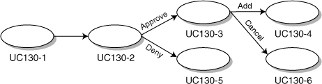
The ordering of these transactions forms a tree in which there are several paths (formed by the constituent transactions) to a successful outcome. The orderings for each use case (with a human actor) in the use case model will lead to a forest of transaction trees.
Transactions from included and extension use cases should be added to these trees. Transactions from included use cases should be added at the point where the use case logic delegates to the included use cases. Transactions from extension use cases should be added at their extension points. Whole trees from these use cases may often be inserted into the including or base use case.
Grouping Transactions and Layout of Logical Screens
If we combined the models we have built so far in the conceptual user interface process, we’d have a set of transaction trees containing informational elements. These trees would be partitioned by the needs of the user community. Such a model is usually relatively large.
If we created screens for each of the transactions, we would probably have a rather large set of screens. This sounds like a lot of work for our user interface developers. But there is a saving grace. There is not necessarily a one-to-one correspondence between transactions and screens. Multiple transactions may be combined in a single screen, and large transactions may drive the development of multiple screens when real estate (number of pixels on the screen) becomes an issue.
The goal of this step is to produce a small set of trees through consolidation. These trees should map to sequences of logical screens. With this small set of trees we begin the process of developing a physical user interface. To consolidate the trees, we need to find transactions with similar information elements. If we relax the minimal information requirement of the transaction information model, we can usually find places where transactions may be combined. The result is a new tree whose transactions are combinations of transactions from different use cases.
Transactions in the same user partition often have common information elements. Transactions are small enough slices of the use case model that their reuse levels (from an information point of view) can be high. Within the same partition, earlier transactions offer the greatest opportunity for consolidation. Transaction paths often diverge from there.
Perhaps the best example of consolidation occurs in systems that begin with a user logging in. Of course, there will be a use case that separates out this behavior, which will be part of many of the other use cases. Combining trees at this point cuts across partitions but moves the transaction information model to its next consolidation point.
For systems that require authentication, such as a login, the user group approach to partitioning is ideal. The login determines the type of user that is using the system and moves the user to the first application screen. This screen is derived from the consolidation of many of the transactions following the login transactions in transaction trees with the user group. In other words, the first thing a user sees after the login is completed is a screen that is specially made for the appropriate user group. This screen presents the first decisions and information needed to make the decisions based on the type of users. In our loan example, customers are given one screen when they log in, bank employees another.
Consolidating transaction trees is a bit of an art. However, the information content does not have to match exactly. Information elements may be moved off the screen when they are not applicable to all transactions or when real estate becomes an issue. Priorities can also be associated with information elements to determine which elements are less likely to be needed by the user in making decisions.
Physical User Interface Design
Once we have an understanding of the information required by the system and the order in which it is needed, we may begin to lay out the physical user interface. Physical user interface design can be done using paper and pencil. However, the best way to do it is through a graphical user interface development tool such as VisualAge or VisualCafe.
During physical user interface design, we start with each consolidated transaction. The elements are translated into push buttons, entry fields, radio buttons, and other widgets based on their information type. Real estate, aesthetics, and usability become prime concerns during this phase. Prototypes may be made [Bowser 1995] and user interface specifications may be updated using screen shots.
Physical user interface development is a book by itself. We refer the reader to Cooper [1995] for overall physical user interface development and Lee [1993] for information type mappings.
Conclusion
Modern user interface development can be much more than the creation of graphical user interface screens. Technology is available to incorporate sound and other elements for users to obtain the desired experience from a software system. The conceptual user interface methods that we have outlined are designed to transfer information from the user to the system, so they may be extended to different media forms.