Chapter 12. Map Use Cases to Object Models
The word VALUE, it is to be observed, has two different meanings, and sometimes expresses the utility of some particular object, and sometimes the power of purchasing other goods which possession of that object conveys.
—Adam Smith, Wealth of Nations [Smith 1937]
What’s in this chapter?
This chapter discusses the mapping and integration of the use case model with a domain and analysis object models. Specific techniques such as CRUD matrixes, use case to object responsibility mapping tables, and sequence diagrams are discussed.
Use cases are a representation of system behavior that is easy for stakeholders to work with. However, a complete understanding of a problem also requires that the analyst consider the static or informational perspective. During system analysis the things that need to be captured, represented, and manipulated by the system must also be modeled.
A conceptual or logical object model is used to model these aspects. The model includes the objects in the domain that the system will be responsible for—the attributes, business rules, and information associated with each object and the relationships between the objects. The use case model captures the behaviors of the system, while the object model describes the static structure.
Davis [1993] describes three characteristics that any analysis approach needs to provide to completely define what he calls a “knowledge structure”—a structured collection of concepts and their interrelationships. These characteristics are:
• Partitioning. Ability to divide or break a problem into its key parts and understand the relationships between the parts.
• Abstraction. Ability to pick out the key aspects of the problem from the more general elements and relationships.
• Projection. Ability to view the relationships and interactions of the components from different external viewpoints or perspectives.
Use cases provide the projection aspect very elegantly. And, while some abstraction and partitioning can be represented within the use case model, the use cases do little to represent the structural aspects, such as partitioning and abstracting of information requirements. Concepts such as associations, aggregation, and generalization within the static object model provide another approach to modeling requirements, complementing the use case model and thereby helping to provide a more robust analysis modeling approach. The combination of the use cases and the object model provides a comprehensive means of capturing a complete analysis of what the problem is and what the system will do.
In traditional structured analysis, data flow diagrams (DFD) provided a functional view of the representation and a logical data model represented the static view [Yourdon 1989]. When an object modeling approach is taken, the use cases capture the functionality of the system, and the object model can be used to capture the static or structural aspects (the object model can be used to represent other dynamic aspects as well).
These representations combine to provide a very comprehensive picture of what the problem is and what the system will do.
These two representations of the requirements need to be integrated. Do the objects defined in the object model represent things that participate in the use cases? Are the objects and relationships defined sufficiently in the object model to support the behaviors in the use cases? The use case can be used to both create as well as validate the objects and their relationships.
In this chapter we examine several approaches to integrating two models. This is not a book on object modeling, but it is important to understand the relationship between use case modeling and object modeling during the overall analysis activity.
Analysis Object Modeling
An analysis object model is at a logical or requirements level of abstraction, so it should reflect things and relationships that make sense to the customers and users. An analysis object model should describe the domain that the system will be responsible for supporting. A distinction is sometimes made between a domain object model and an analysis object model. A domain object model is a high-level conceptual picture of the “domain” or business in which the system will operate. An analysis object model adds more details to the objects based on specific and detailed system requirements. While this distinction is important during a system development effort, for the purposes of describing the integration of use cases and “logical” object models, we do not make a distinction. We encourage the reader, however, to explore this topic further in a good object development process book [see Jacobson 1999].
In any case, the domain or analysis object model should reflect the customer’s business and should use terms that are part of the customer’s business so that it can be successfully understood and validated by the customer. The customer should be able to look at the model and say, “Yes, these objects and their relationships represent things about us and what we do.” A detailed discussion of object modeling at the analysis level is the subject of a large number of references including Booch [1994] and Rumbaugh [1991]. For discussion purposes in this chapter, we use the following characteristics:
Domain and analysis object models describe the problem domain within the context of the system’s overall responsibilities to the business. The classes, their properties, relationships (such as inheritance, associations, and aggregations), and interactions represent the real-world entities. The model is as free from technical or implementation details as possible.
See Figures 12-1 and 12-2 for an example of a partial domain object model for the loan example.
Figure 12-1. Static view of the object with association and aggregation relationships

Figure 12-2. Static view of the object with inheritance relationships

The models and representations used during analysis can be very complex and diverse, and it is difficult to view the pieces from a “flat” or single viewpoint. For example, object relationships and information are represented in the static view of the object model; text-based system behaviors are represented with use cases; and more detailed dynamic aspects can be modeled with sequence, collaboration, and state diagrams. All of this information needs to be integrated and represented. Given this, think of the requirements analysis information as being contained in a large cube with each side of the cube showing a different facet or view of the information (Figure 12-3). For example, turn the cube one way and see the requirements information in its use case form. Turn the cube another way and see it in its static form (i.e., inheritance, aggregation, associations). Turn it yet again and see the object interactions that reflect the behaviors and interactions defined in the requirements. While an analyst needs to be judicious about how much object modeling is performed during an analysis effort (to avoid analysis paralysis), the various facets of the cube can help view, understand, represent, and validate the requirements. Object models provide another set of viewpoints from which to judge completeness and consistency. Also, the different views help to alleviate analysis paralysis by providing more than one perspective from which to attack the problem.
Figure 12-3. Integrated view of requirements analysis information as cube

The use case and object models complement each other, with the object model providing the following benefits:
• It provides a representation of the common business abstractions and their relationships that are a responsibility of the system.
• It aids in consistent descriptions of key concepts.
• It balances the functional aspects of the use case model.
Parallel Use Case and Object Modeling
A common practice we have seen is the definition of system requirements using only use cases, with little or no object modeling. Projects, particularly those with inexperienced developers or developers who are under very tight time constraints, are often be tempted to implement the objects without first taking the time to represent them in an object model. The result is a functional design, not an object-oriented one. All good intentions aside, it is important to take the time to perform the translation (Figure 12-4). Our experience has been that if the analysis models do not reflect a solid object-oriented perspective, it is unlikely that the design model will, defeating the purpose of an object-oriented approach; therefore, we like to make sure that our analysis results provide an object-oriented perspective.
Figure 12-4. Parallel use case and object model development

The challenge, as mentioned earlier, is to integrate the use case model and the object model and maintain consistency between them. The creation of use cases can help in the discovery of the objects as well as facilitate the definition of their relationships in the static object model in support of the interactions between the participating objects in the use cases (Figure 12-5).
Figure 12-5. Mapping a use case to a set of interacting objects

When performing requirements analysis with use cases and object models, a similar mapping issue arises. To ensure that the use cases and the object model stay in sync and that the functionality defined in the use case is reflected in the objects, the following questions need to be addressed:
• Do the objects have the appropriate attributes to support their participation in the use case?
• Do the relationships between the objects—associations, aggregation, and so on—support the interactions that will occur?
• Do the objects have the high-level responsibilities needed to support the use cases they participate in?
Think of the analysis process as analogous to determining the requirements for a new house. The use cases describe how you and your family will use the house, and the object model describes the things in the house that reflect these needs and their relationships. A description of a bathroom outlines the things that are needed to wash your hands and take a shower, such as a sink and a shower. A description of a kitchen would outline the things needed to cook food, store food, and so on. There are several ways of achieving this use case and object modeling integration, including
• the use of basic CRUD matrixes to provide a simple mapping between the use cases and the object model,
• an expanded form of CRUD matrixes that takes into consideration specific behaviors of the use case that manifest themselves in the object model, and
• if a responsibility-driven analysis approach is desired, the use of UML sequence or collaboration models to map the “strings” of object interactions in a specific use case to the static object model.
Basic CRUD Matrix
In traditional structured analysis, it was typical to develop both a process model and a data model and to map the models through the use of a concept called a CRUD (create, read, update, delete) matrix between the two models.
The use of a CRUD matrix is relatively simple and well tested in the data modeling and functional analysis communities. In a CRUD approach, each use case is analyzed to discover any participating objects; this was first discussed in Chapter 7. A CRUD matrix captures four types of interactions with objects:
• Create. Does the use case create an instance of this object?
• Read. Does the use case access this object for the purposes of reading one or more of its attributes?
• Update. Does the use case update any attributes of the object?
• Delete. Does the use case delete this object instance?
In its simplest form, a CRUD matrix is a two-dimensional table with the use cases along the top axis (x) and the objects down the side (y) (Figure 12-6). If an object participates in a use case, note the type—(C) Create, (R) Read, (U) Update, (D) Delete—in the appropriate cell. A partial CRUD for the loan processing system is given in Figure 12-7. For example, the “Book a loan” use case reads information from the loan request object, the evaluation recommendation object, and the loan agreement object, and then creates a loan account object. CRUD matrixes are a simple and effective means of mapping and tracing use cases to objects very early in development. They can also be used to identify the life cycle of objects across use cases.

Figure 12-7. Partial CRUD Matrix for several loan processing use cases

To create a CRUD matrix, determine the “CRUD” that are performed on each object discovered in the use case. For each unique combination of use case and object, create a CRUD entry in the matrix.
CRUD matrixes provide
• a simple and quick means of mapping objects to use cases,
• help in understanding the basic life cycle of the objects, and
• help in ensuring that the information required for each object by a use case is captured.
Expanded CRUD Matrix
Although a CRUD matrix provides a high level and quick mapping of the relationship between the use case and objects that participate in each use case, which in many cases is sufficient during requirements analysis, it does not address the issues of discovering, capturing, and tracing the responsibilities of the objects. Unlike data entities, objects have responsibilities, and they cannot be captured in a simple CRUD format. For example, when a loan application is validated there is a a lot more going on than a simple read. A CRUD matrix format can be expanded to clearly capture more details of the responsibilities. This in turn helps to identify, highlight, and organize specific requirements. To maintain readability, use cases are rarely thorough enough to capture all the detailed requirements. By modeling this information in formal terms, unknowns can be discussed and addressed. At this level of development, we like the word responsibility versus operation (the UML standard) to show high-level functionality, not detailed methods, and to help to avoid premature design.
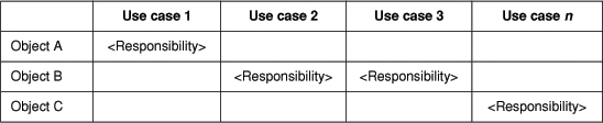
Rather than place a letter (C, R, U, D) in the cell, provide a short description of what object responsibility is involved (Figure 12-8). A responsibility of a loan request is to determine its status and where it is to be routed based on the status. A responsibility of the credit score is calculating the actual credit score. Place more descriptive text in each cell to describe the way the object is invoked. This helps to map the responsibility of the object in the context of the use case model. The expanded CRUD can be referred to as a use case object model (UCOM) matrix.
Figure 12-8. Use case object model matrix
It is important to remember that the purpose of an expanded CRUD is to help structure the problem and to highlight and define more detailed requirements. Note the responsibilities, and then ask questions. For example, what specific information needs to be validated on a loan application, and why?
A use case object model matrix provides
• traceability to and from the detailed requirements within a responsibility to the objects and use cases they came from,
• a layout of object participation within a use case,
• a more detailed look than a CRUD matrix provides at the responsibilities of each object, and
• a way of organizing and categorizing requirements and their details based on responsibilities.
In the use case, “Submit loan request,” a responsibility for validating the information on the application form for completeness is associated with the object modeling the loan application. The object that represents a credit score has the responsibility of calculating the score (Figure 12-9). Again, the objective of a use case object model matrix is to map primary responsibilities from the behavioral representation (use case) to the static representation (object model) to help ensure consistency. When filling in the matrix, new objects that have not yet been discovered and represented in the static object may be found. Update the object model accordingly.
Figure 12-9. Partial use case object model matrix for several loan processing use cases

When creating a UCOM, informally review the use case for how an object participates in the use case and what actions are described that are associated with the objects. Create responsibilities based on these actions and place them in the appropriate cells of the UCOM matrix. Then investigate the detailed requirements, business rules, and business logic associated with these responsibilities. If creating the table is difficult—that is, it is conceptually hard to discover responsibilities—perform object sequence modeling (discussed next) to help clarify the various object responsibilities and then fill in the matrix with the results.
Analysis Sequence Diagrams
Object-oriented analysis can be approached from a data-driven perspective, where the static object model relationships are focused on, or from a responsibility-driven approach, where the dynamic relationships are the primary focus. The approach selected is one of style; we have seen good results from both. If a responsibility-driven approach is selected, models to capture the interactions between the objects in use cases are often used. The reason is that while the CRUD and UCOM matrices are very useful and in many, if not most, cases sufficient for requirements analysis, they can miss some key requirements information.
Also, it is sometimes difficult to clearly see and map responsibilities associated with objects without a more formal modeling approach. For example, an object’s responsibility is performed in the context of a series of interactions. These interactions may represent business rules and procedures, which influence and help identify more detailed logic that can emerge from a more detailed analysis. In addition, it is sometimes difficult to “see” and describe the requirements in a specific responsibility without explaining the context of how they are used. For these situations, we recommend the use of UML sequence or collaboration models.
One of hardest but one of the most important concepts to understand in an object-oriented analysis effort is the overall flow of control. UML sequence diagrams help make the flow of control clearer. A sequence diagram illustrates how the objects in an object-oriented system interact with one another and how messages are sent and received between the objects. In an analysis effort, a sequence diagram can be used to show the string of object interactions that occur in a specific use case.
Many in the object-oriented community view sequence diagrams as strictly a design tool, not an analysis tool. While we agree that a primary role for these diagrams is in design, they are also a useful tool for responsibility-driven analysis situations where more detail is required. Sequence diagrams also help maintain a balance and integration between the use case view and the object view. For, as we have mentioned several times and related in a number of other experiences (Firesmith [1995] and Berard [1996]), there is nothing inherently object oriented about use cases; the use case model needs to be balanced by the object model.
When developing sequence diagrams, keep in mind that at least three stereo-types or types of object can be defined [Jacobson 1992]:
• Entity (domain or business)
• Interface
• Control
Entity objects, also commonly referred to as business or domain objects, model persistent domain “things” that the system will have some responsibility for. These objects are the focus of the domain object model and elaborated in the analysis.
Interface objects model the specific interfaces that an actor has with system in the context of the use case. Interface objects will ultimately map to the GUI interface, to external systems that interact with the system, or to other interface elements for the specific interaction they model.
Control objects model business rules or processes that cannot be placed neatly in an entity or interface object. They capture processes that are global to the use case and don’t nearly fit within a single object. Control objects are the subject of some discussion since they can easily turn into a functional processes. However, their use during analysis helps to understand and represent complex behaviors not associated with any specific entity object. See Jacobson [1992] for additional guidelines.
The objects that participate in a use case interact with each other to perform the behaviors in the use case. These objects pass messages to each other by one object invoking another object’s responsibilities (Figure 12-10), where the professor object is asking the student object for its name. When object A invokes object B’s responsibility, A is said to collaborate with object B. The invoker object normally waits (in a nonconcurrent sequence) while the invoked object performs its responsibility, perhaps collaborating with other objects. Control is returned to the invoker object when the responsibility has been completed. A string of interactions to perform some behavior is called a sequence (modeled in text by use cases). These interactions are modeled by sequence diagrams [UML 1999].
Figure 12-10. Professor object sending get name message to student object

Format of Sequence Diagram
A sequence diagram has two axes and a single entry point at the upper left corner (Figure 12-11). The order of execution is represented as the vertical axis and is read down. The horizontal axis shows the set of objects that are involved in the sequence. Each object is modeled as a labeled rectangle. Below the rectangle is a dashed line (called the object’s lifeline) indicating the object’s use during the sequence. Messages between the objects are represented as directed horizontal solid lines between lifelines. Messages indicate requests for a service and are named for the server’s responsibilities. Text description of what is occurring can be placed along the left side of the diagram.
Figure 12-11. Message passing between two objects in a sequence diagram

In a sequence diagram, during analysis, the client object sends a message to the server (collaborating) object. The message name is equal to the receiver’s responsibility name. The receiver object then performs its responsibility and may return results to the sender object, as in Figure 12-11. Open rectangles on an object’s lifeline can be used to represent when an object has control. The rectangles on the lifeline show the period of time during which an object is performing an action, either directly or through a collaborating object. The top of the rectangle is aligned with the start of the action, the bottom with its end.
A sequence diagram graphically shows the object interactions that result from the execution of the behaviors in a particular use case. An outside message, normally from the actor initiating the use case, invokes a responsibility of object A. Object A kicks off other messages to complete the overall behaviors specified in the use case (Figure 12-12). Object A passes control to object B, and object B must complete the operation, including a message to object C, before returning control to object A.
Figure 12-12. Outline of a sequence diagram

The first object to be invoked is placed at the far left, and the other objects are placed to its right. Normally, the later the object appears in the use case flow of events, the further to the right it is placed. A vertical dashed line represents the object’s lifeline, or its existence over a period of time.
Message Returns
Returns can be either implied—assumed as a condition of the message—or shown explicitly in the diagram. (Tip: Show returns explicitly, but only if it improves the clarity of the diagram; overuse can clutter the diagram.)
Text Description of Sequences
Text describing flow of execution can be placed on the far left side of the diagram. The text narratively describes the illustrated interactions in prose and can include conditionals and iteration. Text can be very useful in improving and enhancing the understanding of the diagrams. When using text, start with the use case flow of events and modify it as new knowledge is acquired during the creation of the sequence diagram.
Preconditions and Postconditions
Just as in use cases, preconditions and postconditions can be associated with a sequence diagram: These conditions can be represented as states in key or important objects in the sequence diagram.
• Precondition. What must be true (or needed to have happened for the sequence to be able to execute).
• Postcondition. The state in which the sequence diagram leaves the system.
Preconditions and postconditions help to bound or scope the sequence diagram. Start with the preconditions and postconditions of the use case being modeled in the sequence diagram.
Figures 12-13 and 12-14 are sequence diagrams for the submit loan request and evaluate loan request use cases. Remember that the goal of analysis-level sequence diagrams is not design but understanding.
Figure 12-13. Submit loan request sequence diagram
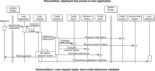
Figure 12-14. Evaluate loan request sequence diagram

Mapping Use Cases to Object Models Using Sequence Diagrams
The process of sequence diagraming starts with identifying the candidate objects in the use cases. The specific inputs into this process include the use cases and the initial object descriptions. Each use case is replayed (if needed) and the outcome of the processes is a refined set of object descriptions, object sequence diagrams, and a refined or created object model (Figure 12-15).
Figure 12-15. Mapping use cases to an object model

A brainstorming technique called role playing can be used to facilitate responsibility-driven analysis. Role playing helps define objects and their behavior and models the interactions among objects and external users (for example, humans or external systems). With role playing, the analysis team creates object descriptions, traditionally referred to as class responsibility collaborator (CRC) cards [Bollin 1997] [Wilkinson 1995], that document each object’s name, description, responsibilities, and other objects with which it collaborates. We like to include object attributes as well, since the role of analysis is to understand the information that will need to be captured.
Role Playing Example
Role playing can be formal or informal, but it always begins by using the initial objects found in the use cases or in other documentation. One approach to role playing would include the following steps:
- Determine the candidate objects in each use case. Select a set of candidate classes that model the problem. Give each class a name and describe what it is and what it does. For each class, transfer its name and description to a CRC card or other form of object description, and create a CRC card for each object.
- Each group member participating in a role-playing session takes a CRC card. The group walks through one use case at a time, simulating collaborations between objects. Each individual plays the role of an object by carrying out its behavior in the context of the use case. As the role playing progresses, object responsibilities and collaborations are identified and documented. On a white board, write down the each class’s responsibilities and any collaborators the class uses to accomplish its responsibilities. New objects are created, if necessary, to complete the analysis. Create a sequence diagram to capture the results of the role playing.
- When a new object is discovered during the role playing, ask if any new associations or other relationships are needed between the objects. In this situation, normally you can wait until after the use case is completely role played and then update the static object model. However, sometimes you get “stuck” creating the sequence diagram and need to explore the object relationships before completing the sequence diagram. In this situation, stop, document the change on the static object model, and then return to the role playing. For each use case, at first focus on the normal flow of events (avoid exceptions and alternatives). Don’t try to do all the functionality described in the problem in one use case; rather, break the problem into easy-to-role-play simple use cases.
- Complete the sequence diagram, and then document any additional detail needed on each object (such as attributes).
- Copy the sequence diagram from the white board. Erase the white board and start with a new use case.
At the end of session you will have
• a collection of sequence diagrams,
• an updated static object model and object descriptions with high level responsibilities, and
• lots of additional questions to ask the user and customers.
While a sequence diagram emphasizes the time ordering of messages, a UML collaboration diagram emphasizes the structural organization of objects that send and receive messages.
Collaboration diagrams combine elements of the static model and the sequence diagram. While we do not discuss collaboration diagrams in detail here, they can be useful as a complement or alternative representation to a sequence diagram. A good CASE tool such as Rational Rose provides an automated conversion between the two diagrams.
Object Modeling Workshops and Ideal Room Setup1
When developing use cases, object modeling, or integrating the models, it is helpful to have facilities and automation to streamline and support the analysis effort. While we have seen very good analysis performed (literally) on a napkin, good automated tool and facility support help the analysis team on a large project with tight delivery times to focus on the important things. Support starts with a good room and equipment (Figure 12-16).
Figure 12-16. Object-oriented analysis room

In this room dedicated to the project, white boards line the walls, and static object models can be created and modified on the boards as the team progresses through its analysis. Since the static object model “lives” through time, it has its own dedicated white board(s). The use cases and sequence diagrams are typically developed one at a time. We like to use a recordable white board to create the sequence diagrams and use cases, print them out, erase the white board, and start again. Project issues, assumptions, and schedule information can be presented on another white board or flip charts.
The results of the session are then transcribed into a CASE tool support. CASE tool support is critical on a large project, although capturing and changing aspects of the object model in a CASE can be difficult during a very dynamic and free-flowing brainstorming session. We like a manual process for the capture, with the results directly entered into the CASE tool.
Issues with Using Sequence Diagrams during Analysis
A sequence diagram provides an effective graphical view of the object interactions in a specific use case’s flow of events, along with a means for verifying collaborators, a way to visually identify overly busy classes, and a means for discovering frameworks and patterns. Guidelines for using sequence diagrams during analysis include the following.
• Keep in mind that use cases that represent simple updates and queues normally do not need sequence diagrams. Use cases that represent behavior with complex logic or that needs further clarification benefit most from sequence diagrams.
• The results of a sequence diagram can be placed in a UCOM matrix (or can be automatically generated if you are using a CASE tool that supports the generation of traceability reports between the use case and objects) and each responsibility can then be explored in more detail.
• Sequence diagrams can help find patterns and frameworks in the analysis effort. Factor visual patterns out into include relationships.
• Keep sequence diagrams at the analysis level. Don’t get caught up in long design discussions.
• Give each sequence diagram the same name as the name of the use case it is modeling.
• Use the use case flow of events as the default text at the left side of the sequence diagram. It will, however, in all probability become more detailed as the analysis proceeds.
• If arguments occur over where to place a responsibility, ask if it is really a design issue and remember that the goal of analysis is to understand the problem. Select a reasonable object in which to place the responsibility, document the rationale for the decision, and move on.
• Keep the message names informal; the descriptions of the messages should be written to reflect requirements. If there needs to be a description of the operations behaviors, stay away from writing pseudocode, although business rules and mathematical algorithms that express requirements should be documented.
Conclusion
In this chapter, we outlined the rationale and several approaches for creating and maintaining consistency between the use cases and the object models. We discuss several techniques including simple CRUD matrices, use case to object model matrices (UCOM), and UML sequence diagrams. Although this is not a book on object modeling, we outlined key object concepts that can be captured from information in the use cases.
We feel strongly that to effectively clarify, organize, and validate the system requirements, a requirements analysis needs (at least) both the use case model view and a static object model view. Considering the requirements only as use cases will almost always assure that requirements for a large system development will be missed.