
Chapter 15. Organize the Use Cases
What’s in this chapter?
This chapter discusses organizing use cases by business functional packages and by dependencies based on use case preconditions and postconditions. A discussion of various views of the use case model is presented. A wrap-up of key use case artifacts is also presented.
As we have seen, use cases provide an excellent means of modeling and understanding functional requirements. An individual use case captures system requirements based on the interactions between actors and the system. However, in our understanding of system behavior, something is still missing. There are larger system behaviors that will cross multiple use cases. For example, is there a need for the system to perform an integrated process or work flow that will span multiple system use cases? If so, there will be requirements that need to be identified and associated with not just one use case but with a “stream” or grouping of use cases. Particularly in a large system, the use cases can also naturally be grouped into common business functions, such as billing, customer service, accounts management, and so on. Organizing the use cases into these business functions helps improve the understandability of the model, document the scope of each business function, and partition the system for development.
The discovery and modeling of use cases often drives the discovery of additional use cases in each business function. When systems are very large, there may be hundreds of use cases—so many, in fact, that stakeholders need an intermediate level of organization to provide more clarity to the model. If the use cases are presented only as a large list, users and analysts can have a difficult time understanding the “big picture.” Although use cases provide an intuitive and natural way to model a system, it can be hard to get a conceptual grasp of a system when it is represented as an unordered set of use cases. This chapter focuses on several ways that the use case model can be organized to facilitate the improved understanding of system requirements.
Although we present these techniques as the last of the major activity groups and in a separate chapter at the end of the use case modeling process (Figure 15-1), the organization of use cases normally occurs as iterative activity spanning the use case model process, from the initial definition of the use cases through their elaboration. We encourage the analyst on a large system effort to organize use cases progressively as the use case modeling process unfolds.
Figure 15-1. Many use cases comprise a system

It is usually beneficial to view the set of use cases from a number of different perspectives. We have already looked at several organizational mechanisms such as the use case diagrams that represent the relationships between individual use cases and actors and include, extend, and generalization relationships between use cases. In this chapter we look at four additional techniques to help organize system use cases:
• Superordinate and subordinate use cases
• Use case model views
We use UML concepts such as packages and activity diagrams to help us represent these concepts.
Business Function Packages
The human mind has difficulty understanding and comprehending large amounts of unorganized information. Recall the 7 ± 2 rule that was used when modeling with traditional structured analysis (structured analysis is documented in a large number of references; see DeMarco [1979] and Yourdon [1989]). The guideline was to try keep the number of process bubbles in one data flow diagram at around seven, on the premise that the human mind can most effectively conceptualize and remember about seven major items in a diagram or other artifact. A data flow diagram with 30 process bubbles was a nightmare to read, follow, and remember.
In a very large system, there can be a large number of possible use cases. While use case modeling is clearly not structured analysis, throwing 50 use cases at a customer without any meaningful ordering or organization will be decidedly unsuccessful. Grouping the use cases by actor or by use case family is useful in many situations, but there will be times when a customer may wish to view the use case in different arrangements. In this section we look at grouping the use cases by the larger functions that make up a system.
It is natural for customers and users to think of a system as a set of key business functions or features. These business functions are broad responsibilities of the system and can be viewed from a functional perspective. The business functions are the next level of abstraction down from a system level context or use case diagram. For example, the business functions of a library system might include circulation, acquisitions, inventory, and management reporting.
Use cases can generally be grouped by functionality in business function packages. Each functional business package represents a major business activity supported by the system. In the loan processing system, unique business functions are associated with both loan submission and loan maintenance, and customer care. These are defined as separate business function packages. For a large system, partitioning system behavior into business function packages is critical for understanding the system architecture and effectively defining a development strategy.
Jacobson [1997] has discussed the idea of an overall larger system containing multiple smaller systems with each smaller system containing individual use cases; we will return to this discussion later. During the requirements capture activity, we like to think of these groupings not so much as subsystems, but as groupings of business functionality that the system will be responsible for implementing. The name “business function packages” implies that we may not have decided quite yet how to architect and design the overall system. The system architect may ultimately decide to combine several functional packages into a single subsystem or divide a single functional package into several subsystems. However, the focus during requirements analysis should be on the groupings that make the most sense to the users and customers. The division of the use case model into groups is not a new concept in use case modeling. In addition to Jacobson, a number of references discuss the concept, including Rosenberg [1999], Schneider [1998], and Armour [1995].
During the development of the use cases, look for natural groupings of use cases based on the customer’s or user’s perspective. Look at such documentation as previously developed business use cases, business process reengineering (BPR) results, and organizational grouping of responsibilities (based on the stakeholder analysis). In most cases, the grouping will become clear as the use case model is created. Name the business function packages in a way that reflects the user’s and customer’s understanding of the package and the package’s responsibilities within the system.
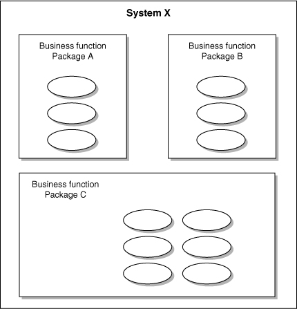
An individual use case belongs to one package, and each package can contain multiple use cases (Figure 15-2). This representation has a number of benefits:
• It represents high-level functionality from a business function perspective.
• It organizes the use cases into logical groups that assist in making the use case model more structured and organized.
• It helps to validate that for each business function the needed use cases exist and none are missing.
• As input into the system architecture definition process, it helps to create the functional architecture.
Figure 15-2. System use cases grouped by business function packages
For example, in the loan processing system, the following business function packages could be defined:
• Loan submission and origination
• Loan account maintenance and care
• Loan portfolio analysis and reporting
• Credit management
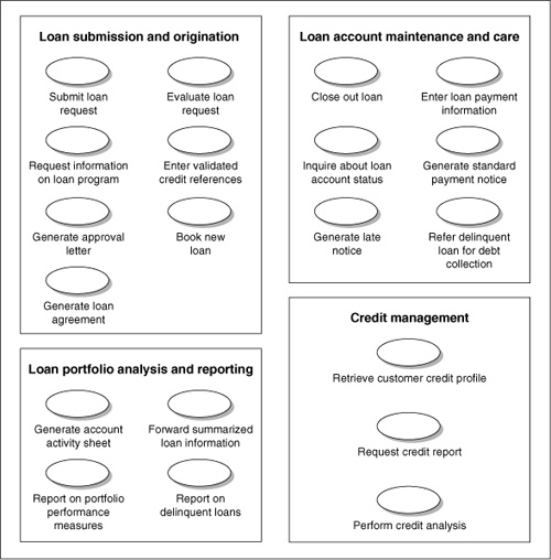
Figure 15-3 shows a use case diagram partitioned into these business function packages with selected major use cases. If desired, the actors participating in each use case could also be included in the diagrams.
Figure 15-3. Partial use case diagram showing business function packages for a loan processing system
Developing the use case business function packages for the loan processing system organizes the system behaviors by their functions in processing a loan. The model allows the loan system users and analysts to view the major functions supported by the system and to observe the system’s behaviors in supporting these functions. If the system is so large that there are dozens of use cases, consider grouping them into business functions. However, with smaller systems this is probably not needed. Normally one level of business functionality is sufficient, depending on the size and complexity of the system.
Superordinate and Subordinate Use Cases
Sometimes use cases don’t fit neatly in a business function package. A use case may be written to describe a set of behaviors that cross multiple functional packages. Jacobson refers to this as a superordinate use case.
A single, broadly defined use case may span multiple business functional packages, with the use cases specific to each individual business functional package supporting behaviors defined in the broader use case. Jacobson [1997, 1995c] refers to this relationship as one between superordinate use cases and subordinate use cases. A superordinate use case is associated with the overall system and can map to multiple subsystems that contain subordinate use cases, with the individual subordinate use cases partitioned into individual subordinate groupings such as business functional packages. In other words, the different pieces of the each superordinate use case can be partitioned to the individual packages. Jacobson refers to the overall system as the superordinate system and the functionality groups as the subordinate systems. Certain use cases can be associated at both the superordinate and subordinate levels (Figure 15-4). The intent of superordinate and subordinate use case organization is not to design or structure the system; it is to arrange a use case in a meaningful and understandable structure.
Figure 15-4. Superordinate and subordinate levels

Use cases at the superordinate level typically are used to represent overall system behavior and cross multiple subordinate systems. The behaviors in the superordinate use case can be partitioned across multiple subordinate systems as subordinate use cases, with each subordinate use case associated with a single subordinate system. Potential requirements associated with the interfaces can then be highlighted between subordinate systems and defined in detail during system architecture. Using this type of division also allows the development of system functionality by subsystems.
One approach is to define the overall superordinate use cases, and as subsystems are identified, develop subordinate use cases for each subsystem based on behaviors in the superordinate use cases. For example, in a large telecommunication system, a superordinate use case “Generate a bill” may involve multiple subsystems, including event rating and pricing, bill presentations and generation, and so on.
While it is not the goal of use case models to architecturally structure the system, for the requirements analysis process extremely large systems will need to be partitioned across subsystems (which can be, in effect, large systems themselves, each of which involves extensive analysis efforts in its own right). The overall requirements of the superordinate system will drive the requirements of the subordinate systems, so the relationship between the two sets of requirements is important to define. For small systems, it makes no sense to partition the system use cases in this manner, since the users who validate the use cases in all likelihood will not benefit from having to know the structure of the system (at least during requirements analysis). In this multilevel representation of use cases, the activities represented in the superordinate use case would be broken down and represented as use cases in their own right.
The relationship between superordinate and subordinate use cases does not have to be as strict as include relationships. The subordinate use cases need to be derived from the requirements modeled in a superordinate use case, but the subordinate behaviors do not need to be strictly included in the superordinate use case.
Using this approach to model the loan processing system, we could document superordinate use cases for such major activities as the loan request submission process (from submitting the request to booking the loan) and the payment process (from generating the payment notice to recording the actual payment). The use cases in the individual business function packages, such as loan submission and origination, would be contained or represented in the superordinate use cases.
Since use cases model requirements, it is instructive to discuss how traditional systems engineering deals with the concept of multiple levels requirements using allocation and flowdown.
Allocation and Flowdown
In traditional systems engineering, two concepts are used when partitioning a larger system into subordinate systems [Dorfman 1997]. In allocation, each system level requirement is assigned to one or more subordinate systems. The requirements are, in effect, partitioned across multiple subordinate groupings, as shown in Table 15-1.
Table 15-1. Allocating requirements to subordinate systems

The next concept is that of flowdown. Flowdown is the actual writing of subordinate system requirements in response to the allocation (Table 15-2). For example, when a system-level requirement is allocated to a business function package, additional requirements will need to be written to reflect the responsibilities of the subordinate business function package. Normally, more than one requirement is written; each represents detailed functionality. It may be just an elaboration of the higher-level requirement or it can represent new behavior discovered, if new functionality is needed to meet the higher-level requirements. (These requirements are sometimes referred to as derived requirements.) When performing this activity, new system requirements will be added, old ones deleted, and modifications made to existing ones.
Table 15-2. Flowdown of the requirements from a superordinate system to a subordinate system

Use cases can be viewed as requirements for purposes of allocation and flowdown. When modeling requirements with use cases, superordinate use cases are allocated across subordinate systems (in this case, represented logically by business function packages, as shown in Tables 15-3 and 15-4).
Table 15-3. Allocating superordinate use cases to subordinate systems

Table 15-4. Allocating superordinate process loan submission use cases to subordinate systems

Then the subordinate use cases are created in response to the flowdown (Tables 15-5 and 15-6).
Table 15-5. Use case flowdown from superordinate to subordinate use cases

Table 15-6. Use case flowdown from “Process loan submission” use case to subordinate use cases in loan processing example

The specification of a flowdown is not a linear process; rather, it is very iterative. Lower-level use cases may be found first and then traced to superordinate use cases as a result of the process. Good traceability should be maintained throughout the process. It should be noted that derived requirements or subordinate use cases do not have to blindly map to the individual activities in the superordinate use cases or high-level requirements. While they should result from them, new behavior may be discovered to support the higher-level use case. Don’t force superordinate use cases if they don’t naturally exist; in many systems the use cases will naturally fit into individual business function packages.
Business Function Package Conclusions
To create a use case business package model, review the use cases, observe natural groupings of functions, and organize the use cases into packages based on business activities. The use case model will then show each package and the use cases that the package contains.
Relationships can exist between use cases in different business function packages. For example, a use case in one package can have an include relationship with a use case in another package. The use case “Submit loan request” in the loan submission and origination package has an include relationship with the “Request credit report” use case from the credit management package.
If there are a large number of relationships between package boundaries, question whether the organization is correct. Ask if the business function packages are defined too narrowly. Revisit the package organization to determine whether they can be reorganized to a higher level of abstraction.
When looking for subordinate use cases, see if there are use cases currently defined that cut across multiple packages. (Hint: A use case provides measurable value to many actors.) For example, multiple actors would participate in the use case “Process loan submission” and a number of them would receive some value from the use case. Consider it a potential superordinate use case. Partition it into multiple subordinate use cases, such as “Submit loan request,” “Evaluate loan request,” and so on. As more business function packages are found, more detailed use cases will be found. Text usually supplements the information shown in the model to help capture more detail about the business functional packages and to provide an overview of the packages. The text can include the description and purpose of the business function packages and reference to the organization that “owns” the business functionality (if relevant).
Dependency Streams
Within a use case’s flow of events, the activities that make up the flow have a relationship with each another. Some activities need to be performed before other activities can be executed, while other activities can be performed in parallel, and some activities can be performed only after another activity. For example, within the “Submit loan request” use case, the activity of entering the loan application into the system has to occur before the activity of validating the loan application can occur (Figure 15-5).
Figure 15-5. Dependency between two activities in a use case

Relationships between activities model important system requirements. If each activity was looked at only in isolation, without regard to how the other activities affect it and how it affects other activities, a large part of the system requirements would be missed. The strength of use cases is that they naturally capture relationship requirements.
But what of the relationships between the use cases? In addition to these extend and include relationships, use cases can sometimes depend on other use cases completing execution before they begin to execute. An individual use case can be analogous to a single activity, except on a higher level of abstraction. For example, in a library system, the concept of a returning library material (“Return library material” use case) depends on the patron borrowing the library material (“Borrow library material” use case) in the first place, as captured in the preconditions and postconditions of the use cases. Borrowing a piece of library material is a prerequisite to returning the material.
In most complex systems, there will be use cases that depend on other use cases leaving the system in a certain state. In addition to understanding the individual system interactions documented in each use case, it is useful to understand how use cases depend on each other. We refer to these relationships as use case dependency streams. Dependency streams model a stream of use cases that are dependent on each other to perform a larger system process. (Please note that dependency streams are not a relationship defined in UML.)
For example, the activity of processing a loan application involves several use cases, including “Submit loan request,” “Enter validated credit references,” “Evaluate loan request,” “Book new loan,” and so on. The relationships between them can be documented with dependency streams. Dependency streams help answer the following questions.
• How do the use cases interrelate to support this activity?
• What use case must execute before another can begin its execution?
• Are there subordinate or superordinate use cases that need to be created?
A dependency stream models the relationship that exists between individual use cases in order to perform some overall system process. In the example of the library system, a patron needs to have borrowed a book before the book can be returned or be overdue. In other words, the “Borrow library material” use case leaves the system in the state “Library material borrowed,” which allows the use case “Return library material” to execute. The directed line between the use cases represents a logical dependency that one use case has on another. In this case, precondition of the “Return library material” use case matches or at least contains the postcondition of the “Library material borrowed,” defined as the outcome of the “Borrow library material” use case (Figure 15-6). Please note that the directed line points to the use case that has the dependency on the other use case (the reverse of traditional UML representation). This is to display the show through, the dependency, or the overall process it models.
Figure 15-6. Matching preconditions and postconditions

In another example dealing with a library system, for a library book overdue notice to be sent out, the book must have been borrowed, and the borrowing must have been associated with a return date.
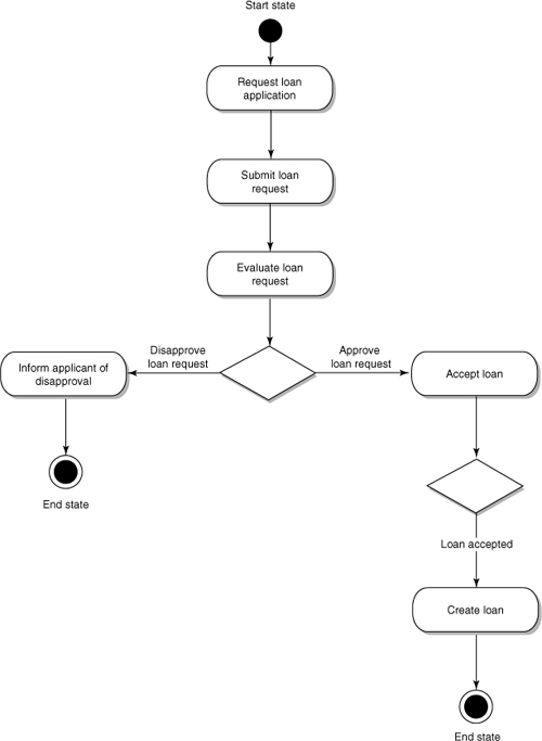
Thinking about the requirements in this manner also helps to specify what behaviors each use case needs to have. For example, submitting a loan request needs to leave the loan request in an initial validation state. The next step in the bank’s loan submission is bank validation of the references on the application. Once that occurs, enough information has been collected for a formal evaluation (modeled in the “Evaluate loan request” use case). What information and documentation needs to be gathered to allow its evaluation? What is the final state of the loan request when the “Submit loan request” use case is finished? Does this state allow the validation of references to occur, which then allows the behaviors in the “Evaluate loan request” use case to occur? In Figure 15-7, a dependency stream is presented for a normal flow (a loan request is approved and accepted with no problems).
Figure 15-7. Use case dependency stream for the loan request submission and approval process

At first glance, dependency streams seem very similar to superordinate use cases. However, they can be applied in a somewhat different manner. First, processes are partitioned into system use case cases, although the processes themselves may not naturally be reflected as use case. Even if a dependency between several use cases is important to understand, it may not constitute an entirely new superordinate use case. Dependency streams help us keep a system use case model as flat as possible, which we like, in order to prevent functional decomposition.
At the same time, dependency streams reflect a strong relationship between use cases; that is, one use case depends on another finishing its execution before it can start executing.
When attempting to organize use cases in dependency streams, look at each use case’s preconditions and postconditions. Are there use cases with postconditions that are preconditions in another use case? If so, this may be a signal that one use case may depend on another. Ask questions such as the following.
• Is there a natural dependency between the use cases? If not, don’t try to force a dependency between the use cases.
• If there is a dependency, what is its nature?
• Do activities need to occur in the first use case for the second use case to successfully execute?
• How will the important exceptions or variations in the first use case affect this dependency?
• Are there timing requirements across the use cases as well as between the use cases? Is there a requirement that the entire process execute over a defined period of time? How is this larger requirement partitioned to the individual use cases? How soon does one use case have to begin after another one has completed?
If use cases have preconditions that don’t map to another use case’s postcondition, ask the following questions.
• Are there system activities that have not yet been modeled? If so, what are they? Is the missing activity within an existing use case or is an entire use case missing? Missing use cases may be signaled if a use case’s precondition does not match to an existing use case’s postcondition. However, not all use cases depend on another use case, so don’t force this issue if no dependency exists.
• Are the use cases defined in the use case model at the same level of abstraction? If the preconditions and postconditions don’t naturally map together, it may be that they are defined at different levels of detail. If so, rework the use cases.
Dependency streams help to validate preconditions and postconditions. Matching use cases in this manner helps to validate that the preconditions and postconditions are written in a consistent manner and are at the same level of detail. A use case dependency stream can also help to point out where a larger superordinate use case needs to be created or where a large system process needs to be partitioned across multiple system use cases.
If the transition from one use case to another crosses business function package boundaries, dependency streams can help point out package interfaces (Figure 15-8), which in turn point out possible interface requirements that need to be explored during system architecture. However, if an iterative development effort is taken, particularly one that develops the system one subsystem at a time, the interfaces between the subsystem become requirements, and need to identified and modeled.
Figure 15-8. Highlighting interfaces between business function packages

Activity Diagrams to Model Use Case Dependencies
In Chapter 9, we discussed the use of UML activity diagrams for modeling a complex use case flow of events. We have found activity diagrams to be a useful tool for in modeling use case dependencies, as well.
To model a dependency stream in an activity diagram, each use case is represented as an activity in the diagram. The dependency between use cases is modeled as a transition between the use cases. If a variation in one use case affects the execution of a use case that depends on it, the analyst can use branching and guards to model the relationship.
In a library example (Figure 15-9), a precondition of borrowing is that the borrower is a member of the library, which is a postcondition of the use case “Apply for library membership.” The postcondition of the “Borrow library material” use case is that the material is borrowed, a precondition for returning it. The use cases that make up the loan application submission process are modeled in Figure 15-10.
Figure 15-9. Simple dependency stream for library system

Figure 15-10. Activity diagram for dependency stream modeling the loan submission process
Dependency streams can include conditional logic and iteration, if needed, but we typically use them as more informal tools to help understand the relationship requirements of system. They also make an excellent tool to model the work flow that a system will need to implement. By the way, UML state diagrams can also be used to model dependency streams; each transition between the states represents a use case.
Model Views
As you can see, there are a large number of ways to organize use cases. We like to think of them as views on the use case model. Depending on the view, use cases can be rearranged for presentation and analysis. In Table 15-7 we outline several views of the use case model. No one view is superior or more right than the others; they are simply alternative means of presenting information. The views can be considered virtual and like the sides of cube, with the use case model inside the cube. The views can be combined, for example, by grouping all use cases by business function package, and then inside each package subgrouping the use cases by primary actor.
Table 15-7. View of the use case model

The table is not an inclusive list of views; individual developers will no doubt discover additional views that are useful for them. The idea is to think of the use case as a multidimensional model and rearrange it in ways that help to discover, model, and represent requirements.
Putting It All Together in a System Use Case Model
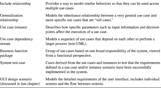
The last 11 chapters have discussed a large number of possible use case modeling techniques and concepts. The use case model “packages” these concepts in a form that represents what the system will do. As a wrap-up, Table 15-8 provides a quick overview of the basic types of concepts and descriptions in a use case model.
Figure 15-8. Basic types of concepts and descriptions in a use case model

Conclusion
A use case model defines a system’s behaviors within the context of the business environment in which it operates; business function packages help group use cases into the larger functions that they will participate in. Dependency streams are used to model how individual use cases depend on each other based on preconditions and postconditions. Finally, use case views can be used to look at the use cases from multiple perspectives for validation and analysis.