Chapter 9. Elaborate the Base Use Case Description
What’s in this chapter?
This chapter discusses the practice of creating alternative flow descriptions and placing conditional logic in a use case’s flow of events.
In the previous chapter we focused on describing the ideal behaviors of a use case in a base use case description. We now discuss techniques for expanding the base use case descriptions:
• Describing alternative flows, which list the flow of events that occurs when an alternative or exception occurs in the use case
• Using conditional logic directly in the flow of events to document exception and alternative processing that occurs during the flow of events
We refer to a use case description that has been expanded in this manner as an elaborated use case description.
As discussed in Chapter 8, base use cases typically avoid detailed descriptions of alternative flows and conditional/iterative logic (if-then and while logic). Although this makes sense early in the modeling of the use case, as more elaborated functionality is discovered and documented in the use case model, alternative flows and conditional logic can be a useful approach for capturing the added complexity.
As more information is gathered about the requirements the use case is modeling, a number of choices must be made about how the information will be represented. This chapter first discusses alternative flow descriptions and then describes the practice of placing conditional and iterative logic in a use case’s flow of events. It presents two formats for modeling these concepts: text written directly in the use case template and UML activity diagrams.
Describing Alternative Flows
Normally a large number of possible variations, alternatives, and exceptions can occur when a use case is executed. What behaviors will occur if the borrower’s credit is bad? What if a customer attempts to withdraw funds from an ATM machine and the customer’s account does not have sufficient funds?
Alternative Flow Descriptions
Since these alternatives and variations can represent significant functionality, it is necessary to think through the implications of the alternatives and document them as part of the use case description. One approach to documenting alternatives is through the use of alternative flow descriptions. An alternative flow description documents the specific behaviors that will occur if an alternative or variation from the base flow of events occurs. An alternative can include such things as a different processing option based on user input, a decision taken within the use case flow of events, or an exception condition that results in a different set of behaviors executing.
Alternative flows can be documented quickly and briefly in the base use case description (as discussed in Chapter 8) or, if the details are viewed as representing important requirements, they can be written in separate description templates (Figure 9-1). Remember, however, that alternative flow descriptions are part of the use case, not separate use cases. A sample template for an alternative flow description is presented in Figure 9-2.
Figure 9-1. Base use case description and alternative flow descriptions

Figure 9-2. Alternative flow description template
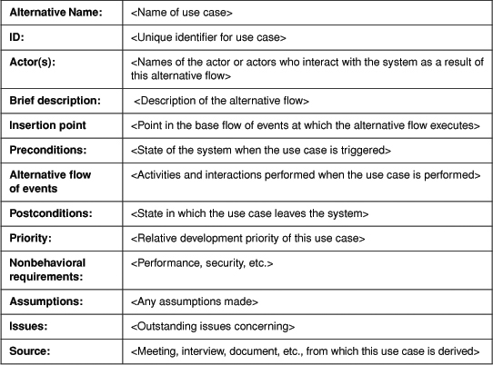
An alternative flow description can have many of the same fields as the base use case description. Included in the alternative flow also is a new field that documents its insertion point in the base flow of events (where it starts its execution). Although the template contains a number field, it may not be necessary to document simple alternatives in great detail; the key behaviors that will occur and the point in the base flow of events that they will be executed may be enough. An example flow description for the alternative of disapproving a loan request in the “Evaluate loan request” use case is shown in Figure 9-3.
Figure 9-3. Alternative flow description: Disapprove loan request

Not all alternatives or exceptions need to be represented with separate alternative flow descriptions. In many cases, it is sufficient to document them in the alternative flow section of the base use case description. However, for alternatives that need to be explored in more detail, alternative flow descriptions can be useful. We normally model only the major alternatives to the ideal flow with alternative flow descriptions. If an alternative has requirements that are unclear, unknown, or highly likely to be misunderstood if they are not explored and documented, consider writing an alternative flow description for them.
Adding Alternative Flow Details Directly to the Base Use Case Flow of Events
As an alternative to an alternative flow description, details about the alternative flow can be added directly to the use case flow of events. The advantages include the following.
• By representing the more detailed behaviors in the use case’s flow of events, the stakeholder has only one place to look to validate the use case’s requirements.
• In-case descriptions are useful for representing situations where there is not really a primary flow and variation but where there are several subflows within the flow of events that are considered (at least by the customers and users) to be relatively equal in importance.
• Small exceptions or variations that do not warrant a alternative flow description can be captured.
Text-Based Conditional and Iterative Logic in the Flow of Events
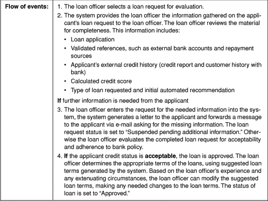
Conditional logic can be added directly to the flow of events text to represent the different results that are possible when determining an applicant’s account standing. In Figure 9-4, conditional logic has been added to the “Evaluate loan request” use case reflecting alternative processing and exception conditions: The elaborated detail describes what happens if the customer does not have good credit. (Note that the conditional logic could have been represented as an alternative flow.)
Figure 9-4. Conditional logic in the “Evaluate loan request” use case


The use of conditional logic tends to highlight use cases that when described at the conceptual or base level of description seem to represent a set of broad behaviors, but that when elaborated really represent two or more use cases. For example, a single base description might describe the event of submitting a loan request. Then, when the details and conditional logic of the use case are refined, it might become clear that processing loan requests from individuals may be very different from processing those of businesses. Different materials need to be submitted with a business loan request, such as financial statements, business plans, market analysis, and so on, which are not required in the case of individuals.
Conditional logic and alternative flows obviously both overlap and diverge in the concepts they attempt to model. In the case of a loan request, a generalization relationship is created by splitting the use case into at least two use cases—“Submit business loan request” and “Submit consumer loan request”—each of which details the unique behaviors associated with the different type of applicant. In fact, one of the advantages of refining a use case flow of events with more details and conditional logic is to identify generalization relationships that would not have been clear without the added level of detail. If the use case is split, remember to update the list of actors to reflect two new actors: the business applicant and the individual applicant. In this instance, the conditional logic that highlighted the differences goes away as two specific and linear use cases are created.
When should you use conditional logic and when should you use alternative flow descriptions? We like to use the following heuristics.
• If the alternative/extension is very complex and long, use an alternative description, since it will clutter up the flow of events if it is placed in the base use case.
• If the variation or exception is very important for the user’s understanding and validation of the main flow of events, then use conditional logic.
• If the alternative is short or will occur frequently when the use case is executed, use conditional logic or simply list it in the exceptions section of the use case.
• If multiple paths course through the flow of events and no one path is considered primary or more basic than the others, use conditional logic. However, this condition should raise a red flag, as it may indicate that the use case needs to be split into two or more use cases.
• If the alternatives have different development priorities, then use alternative flows so that each one can be annotated with its relative priority.
This elaboration should be done to help validation efforts. Elaboration should never confuse or obfuscate the issues. This goal will help greatly in avoiding the detailed flowchart-style exposition that sometimes causes a use case to look like a technical design.
In a use case modeling effort, conditional logic, alternative flows and extend relationships can complement each other. Use them when appropriate, and don’t be afraid to experiment to see which gives the best results, based on the context in which they are being used.
Iteration in the Use Case’s Flow of Events
Sometimes when a use case flow of events is executed, a single activity or group of activities is repeated multiple times. In these cases, it is useful to represent iteration directly in the use case’s flow of events. For example, in the use case “Generate loan approval report,” a report is generated to summarize the amount of money approved in new loans. The system needs to gather information from each newly approved loan and calculate the total amount of all loans. This behavior could be represented as an iteration over a set of loans to gather the necessary information.
Iteration can be documented either informally or formally. Informally, a statement could be added to the flow of events: “Add and total the amounts of individual loans to calculate the total outstanding loan portfolio.” Alternatively, while or repeat loops can be added directly to the use case’s flow of events. More formal looping structures are useful when more than one activity is involved. However, remember your users: iteration can be very hard to follow and understand.
If your use case has a large amount of iteration, or if the entire use case seems to iterate—i.e., the flow of events begins with an iteration statement and ends with its closure—ask if the use case can be represented singularly. A use case such as “Generate standard payment notices,” which has to cycle through the loan customers and generate and print out monthly bills, might be better represented as “Generate standard payment notice,” with the description section of the use case documenting the fact that it needs to do this for all loan customers every month.
Applying Conditional Logic to Use Cases
When developing elaborated use case descriptions, be sure to keep the descriptions and logic at a manageable level of detail. The objective is to understand the requirements, not to write the code. Develop only enough detail for the stakeholders to understand and validate the requirements. If there are many exceptions, list them separately as alternatives in the “Alternatives” section of the use case description or as a separate alternate flow of events of the use case. We find that one level of conditional or iterative logic is normally readable; deeper nesting is very difficult to follow, particularly for nontechnical readers. Develop standards for the structured text, and remember your stakeholders’ backgrounds when you do this.
Try to keep the level of detail approximately the same throughout the use case. If a specific activity requires significantly more detail to explain, provide it in an include relationship or alternative flow description.
In moderation, added details can aid the stakeholder’s ability to validate the use case and ensure that requirements are not missed. However, as with any technique, it has its limitations. If too much detail is added, the use case’s flow of events will become very long, possibly pages and pages, significantly decreasing the stakeholder’s ability to follow the flow and validate the requirements. A long flow also makes the use case more monolithic, less capable of being partitioned so that its behaviors can be reused across use cases. For these reasons, we add very detailed logic to the use case carefully, primarily to highlight very important details in the main flow. If there is a lot of complexity that just can’t be left out, we use alternative flows, include relationships, or other supplemental specifications.
We try to limit the entire flow of events to one or two pages of text. If there is more than that, ask if more than one use case is being modeled, and consider the use of include or alternative flow descriptions to isolate the details. When adding details to the use case flow of events, strive for a balance between the need for details to meaningfully capture the requirements and the need not to overwhelm the stakeholders with details. If the use case has too little detail, the validation of the use case will not be effective. If it has too much, the customer and users will get lost and the use case will be harder to validate. We have seen both extremes. In one project, the use cases stopped at the base or conceptual level, and the project teams were not able (or willing) to capture and validate the requirements successfully through other means, resulting in “assumed” requirements and, of course, the wrong set of system features developed. In another project, the use case flow of events was too long and the customer rejected the use case model because it was not understandable. Nonetheless, detailed requirements have to be captured, specified, and validated to ensure that there are no surprises when the system is built.
A result of conditional logic within the use case flow of events is that different subflows have different outcomes and different postconditions, complicating the documentation of the postconditions. When modeling alternatives or exceptions directly in the use case’s flow of events, determine what effect these alternatives or exceptions will have on the postconditions. In these cases, either generalize the postconditions to reflect the results of both flows or note multiple postconditions, based on major alternatives described in the use case’s flow of events. If the postcondition is generalized to reflect both flows, be careful not to lose so much specificity that the requirements become ambiguous.
A danger with using conditional logic in the use case flow of events is that it can look like design—in fact, it can be taken for a design when it is not. A system use case should not tell the designer to iterate through all the approved loan requests in one step instead of keeping a running total of approvals as the approved loan requests come in. That decision should be left for the designer. Make sure the designers know that iterative and conditional logic is used to help model the requirements and validate them with the users, not to design the system.
It is also easy to make conditional and iterative logic extremely complex by trying to document every possibility formally. Unless there is a compelling reason to provide rigorous formality in the use case flow of events, AVOID IT! A system use case should not design or code the system.
Using Activity Diagrams to Represent a Complex Flow of Events
When the flow of events is linear—that is, it contains little or no iteration or conditional logic—text is usually sufficient to capture and represent the use case information. However, when there is complex logic in the use case’s flow of events, conditionals and iteration can become very difficult to follow. In these situations, consider using UML activity diagrams [UML 1999] as an alternative means to model the use case’s flow of events. Activity diagrams
• provide a visual reference for understanding and documenting complex conditional logic within a use case,
• are an excellent means for presenting complex use cases to the stakeholders,
• can be used to understand the dependencies and relationships between the activities in the use case flow of events, and
• can be used to help clarify and model parallel activities using synchronization bars.
Here we present a short introduction to activity diagrams and discussion of their application in documenting the flow of control from activity to activity in the use case’s flow of events. In Chapter 15 we look at using activity diagrams to model the flow between multiple use cases. For more comprehensive discussion of activity diagrams, see The Unified Modeling Language User Guide [Booch 1999]. For additional discussion on activity diagrams with use cases and examples, see Use Case Modeling: A Practical Guide by Geri Schneider and Jason Winters [Schneider 1998] and UML Distilled: Applying the Standard Object Modeling Language by Martin Fowler [Fowler 1997].
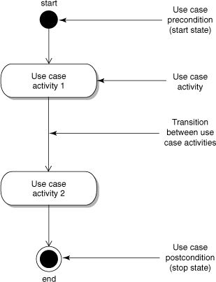
Activity diagrams (Figure 9-5) are easy to understand and easy to utilize in representing the use case’s flow of events. Activity diagrams are composed of activity states, which will map to individual activities within a use case. Each activity in the use case’s flow of events is modeled as an activity state and is given a short name to reflect its purpose. The transitions between the individual activities are modeled by directed lines between the activities. Each activity diagram begins with a start state that maps to the use case’s precondition and ends with a final state that maps to the use case’s postcondition.
Figure 9-5. Simple activity diagram format for use cases
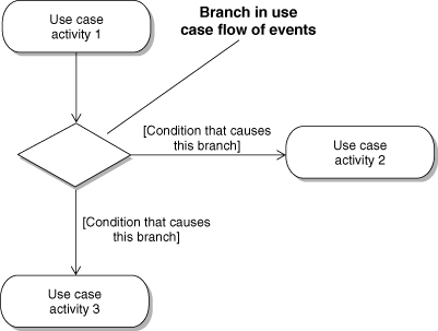
A diamond in an activity diagram represents a transition to different branches or paths through the use case (Figure 9-6). The conditions causing a branch should be documented on the directed line leaving the branch.
Figure 9-6. Branching in an activity diagram
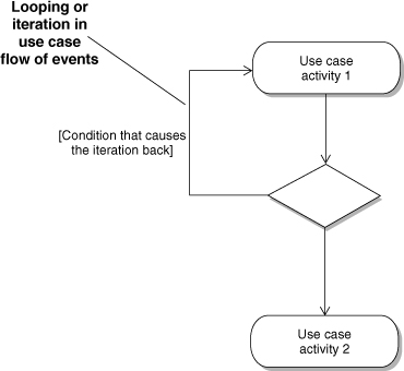
Iteration and looping can be implemented in a similar manner, with the transition line leaving the branch returning to a previous activity (Figure 9-7). All activities between the previous activity and the branch will be repeated until the condition is satisfied.
Figure 9-7. Looping in an activity diagram
Though the use of synchronization bars, activity diagrams provide an excellent means to model concurrency in the use case flow of events (Figure 9-8). A synchronization bar is a horizontal line that models a transition into two or more parallel paths. A synchronization bar is also used when activities sync back into one.
Figure 9-8. Synchronization bars in an activity diagram

Figure 9-9 represents the flow of events for the “Submit loan request” use case. Note the use of conditional logic and synchronization bars. Figure 9-10 represents conditional logic in the “Evaluate loan request” use case.
Figure 9-9. Activity diagram for “Submit loan request” use case
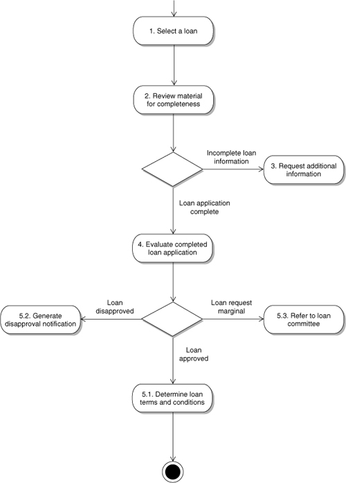
Figure 9-10. Activity diagram for “Evaluate loan request” use case

Activity Diagrams versus Detailed Text
Text can provide a level of detail that diagrams cannot. However, activity diagrams show the flow of events in a more precise and readable fashion than paragraphs of text. The strengths of both text and graphics can be combined by mapping the activity steps in the use case flow of events to the corresponding activities in the activity diagram. If a project is using only an activity diagram to document the use case’s flow of events, don’t forget to capture and maintain the use case information—priorities, actors, and so on. Documenting complete details in both text and activity diagrams can be a maintenance challenge; it probably makes sense to keep details out of the diagrams.
Activity diagrams provide a visual representation of the flow of events through the use case. They are especially useful in representing conditional, concurrent, and iterative logic within a use case’s flow of events and can be very beneficial when validating a complex flow of events. In text, deeply nested logic or iteration can be very confusing for readers. If deeply nested conditionals or a lot of iteration is necessary, activity diagrams can be used instead. Activity diagrams are extremely useful in presenting complex use case flows to stakeholders, customers, and users.
Conclusion
When more information on the use case needs to be captured, the base flow of events can be elaborated with alternative flows and conditional and iterative logic. Alternative flows capture the details of the major alternatives. Conditional logic can be described in the flow of events text or represented in an activity diagram.
Elaboration should enhance the ability of the stakeholders to validate the use cases.